


Installation Manual
Safety instructions
Explanations of the icon's
 Danger!
Immediate dangerous situation, that can endanger severe injury or death
Warning! |
Attention! |
Possibly dangerous situation, |
Possibly dangerous situation, |
that possibly can endanger |
that can engender minor injury. |
severe injury or death. |
|
Corrosive substances |
Fire hazard! |
Danger of burning! |
|
|
Danger! |
Attention: Inobservance can |
Tips and tricks for installation |
High voltage. |
cause material damages. |
|
Caution danger of life |
|
|
Inobservance can endanger |
|
|
severe injury or death. |
V-13 |
- 2 - |
Safety instructions
Warning!
Wrong installation, service, maintenance or cleaning as well as unauthorized changes on the unit can cause damages, injuries or even death. Read the installation manual carefully before installing the unit. This unit may only be used for preparing food in commercial kitchens. Every other usage is against definition and therefore dangerous.
Warning!
Only gas units
-As the unit must be installed underneath an extraction hood, it must be made sure that the hood is switched on during operation of the unit – exhaust gases!
-Don't put any material on the exhaust pipes of the unit – Fire hazard!
-The area underneath the unit may not be blocked or closed by any material– Fire hazard!
-The unit may only be operated in a calm environment – Fire hazard!
 Safety measures in case of smell of gas:
-Immediately close the gas supply.
-Don't touch any electrical switching element
-ventilation of the room.
-Avoid open flame or sparks
-Use an external telephone and inform your local gas authority (in case the local gas authority can not be reached contact your local fire department immediately).
- 3 - |
V-13 |
Dear customer
The warranty excludes glass damage, light bulbs and sealing material as well as damage caused by improper use, installation, maintenance, repair or descaling
Dealer
Installer
Quote in the event of a query: Appliance model:
Appliance no.:
______________________________________
Set to gas type:
______________________________________
Your appliance was checked by:
______________________________________
We reserve the right to make technical changes in the interest of progress!
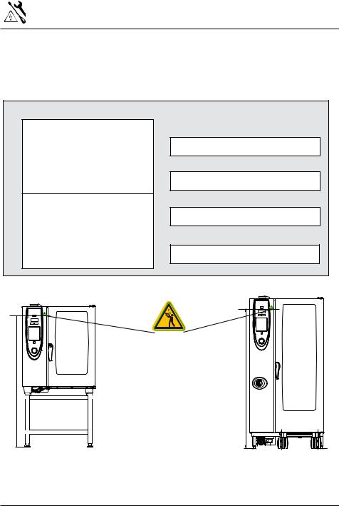
1600 (63")
Safety stickers „Max. rack height for containers with liquid“ are in the Starter Kit.
After Installation of the unit, this sticker has to be fixed to the unit in a height of 1600 mm (see examples)
1600 (63")
 Warning
To avoid scalding, do not use loaded containers with liquids or cooking goods which becomes fluid by heating in higher levels than those which can be easily observed.
Danger of scalding!
V-13 |
- 4 - |

Installation instructions
 Attention:
Follow the local standards and valid instructions. Damages based on installation not complying with the directives given hereunder are not covered by warranty terms.
The required connections (water, electric and gas) may only be carried out by trained/ qualified personal in accordance with the local regulations.
Check for any transport damage.
Should there be any signs of transport damage, inform your dealer/freight forwarder immediately! Remove all cartons, packing materials, documents, etc. from the exterior AND interior cabinet.
Dumping of old units.
At the end of its service life, the unit must not be disposed of with the general waste and must not be placed in the recycling containers at local authority collection points.
We will be happy to help you with the disposal of your unit.
First time commissioning
valid for SelfCooking® Center with CleanJet+Care
When commissioning your new, intelligent SelfCooking Center® for the first time, you will be asked to start an automatic self test. The duration of this self test is approximately 15 minutes and is necessary to adapt the SelfCooking Center® to the specific environmental conditions.
 Fire hazard!
Remove packing material, starter kit as well as containers and grids from intereior cabinet.
m
11:30s
Start
close cabinet door
m
11:29s
Press Start-key, Self test is running, remaining running time is shown
Leave hinged racks respectively mobile oven racks inside the cabinet, Interior cabinet door must not be opened during the complete process of the self test. Opening the interior cabinet door interrupts the self test and when switching on the unit the next time you will be asked to start the self test again. This procedure does not apply to Combi Master units.
- 5 - |
V-13 |

Table of content
Safety instructions |
2 |
Safety instructions |
3 |
Dear customer |
4 |
Installation instructions |
5 |
Table of content |
6 |
Table of content |
7 |
Transport of units |
8 |
Recommended minimum clearance |
9 |
Installation type 6x1/1, 6x2/1, 10x1/1, 10x2/1 GN |
10 |
Installation type 6x1/1, 6x2/1, 10x1/1, 10x2/1 GN |
11 |
Installation Type 20x1/1 GN, 20x2/1 GN |
12 |
Levelling mobile oven racks 20x1/1 and 20x2/1 GN |
13 |
Electrical connection |
14 |
Electrical connection |
15 |
Water connection CareControl |
16 |
Water connection |
17 |
Selection of water filter |
18 |
Selection of water filter |
19 |
Gas consumption |
20 |
Gas connection |
20 |
Gas connection |
21 |
Drain connection |
22 |
Ventilation, technical data, heat emission |
23 |
Option |
24 |
Option |
25 |
Option |
26 |
Mobile floor models 20x1/1GN and 20x2/1GN |
27 |
Mobile floor models 20x1/1GN and 20x2/1GN |
28 |
Mobile floor models 20x1/1GN and 20x2/1GN |
29 |
Mobile floor models 20x1/1GN and 20x2/1GN |
30 |
Mobile floor models 20x1/1GN and 20x2/1GN |
31 |
Mobile floor models 20x1/1GN and 20x2/1GN |
32 |
Connection data USA/Canada |
33 |
Connection data Europe |
34 |
Conversion tables |
35 |
V-13 |
- 6 - |

Table of content
Schematic drawing 6x1/1 GN CareControl |
36 |
Schematic drawing 6x1/1 GN Gas CareControl |
37 |
Schematic drawing 6x2/1 GN CareControl |
38 |
Schematic drawing 6x2/1 GN Gas CareControl |
39 |
Schematic drawing 10x1/1 GN CareControl |
40 |
Schematic drawing 10x1/1 GN Gas CareControl |
41 |
Schematic drawing 10x2/1 GN CareControl |
42 |
Schematic drawing 10x2/1 GN Gas CareControl |
43 |
Schematic drawing 6x1/1 GN |
44 |
Schematic drawing 6x1/1 GN Gas |
45 |
Schematic drawing 6x2/1 GN |
46 |
Schematic drawing 6x2/1 GN Gas |
47 |
Schematic drawing 10x1/1 GN |
48 |
Schematic drawing 10x1/1 GN Gas |
49 |
Schematic drawing 10x2/1 GN |
50 |
Schematic drawing 10x2/1 GN Gas |
51 |
Schematic drawing 20x1/1 GN |
52 |
Schematic drawing 20x1/1 GN Gas |
53 |
Schematic drawing 20x2/1 GN |
54 |
Schematic drawing 20x2/1 GN Gas |
55 |
Schematic drawing 20x1/1 GN Electric, mobile |
56 |
Schematic drawing 20x1/1 GN Gas, mobile |
57 |
Schematic drawing 20x2/1 GN Electric, mobile |
58 |
Schematic drawing 20x2/1 GN Gas, mobile |
59 |
- 7 - |
V-13 |

Transport of units
1
6x1/1 GN:
920mm/36 1/4"
6x2/1 GN:
1120mm/44 1/8"
10x1/1 GN:
920mm/36 1/4"
10x2/1 GN:
1120mm/44 1/8" |
2 |
20x1/1 GN: |
950mm/37 1/2" |
20x2/1 GN: |
1150mm/45 1/4" |
3 |
20x1/1 GN:
920mm/36 1/4"
20x2/1 GN:
1140mm/45"
Transport of units
Transport of units using a pallet pic. 1,2
Transport of units without a pallet, 20x1/1 GN and 20x2/1 GN units only. Put a piece of wood
between pallet jack and left guide rail of |
|
the trolley |
pic. 3,4 |
 Attention
Make sure that the unit is secured against tilting, when transporting it.
Remove all containers/mobile oven racks from the cabinet. For floor model, remove corner mountings from the pallet. Take unit off the pallet.
 Attention
Observe the weight of the units. Use carrying aid to avoid injuries. Wear safety boots.
Weight see technical data on page 23
Observe door height pic. 5 X= Required door width when transporting units
without pallet: |
|
|
6x1/1GN |
33 |
1/8” (840 mm) |
6x2/1GN |
41” (1040 mm) |
|
10x1/1GN |
33 |
1/8” 840 mm) |
10x2/1GN |
41” (1040 mm) |
|
20x1/1GN |
36 |
1/4” (920 mm) |
20x2/1GN |
45“ (1140 mm) |
|
4 |
|
|
5 |
|
|
|
|
20x1/1 GN / |
|
Center |
|
|
20x2/1 GN: |
|
of Gravity |
|
|
1900mm/75" |
|
F |
D |
|
|
|
r |
o |
|
|
- 20x2/1GN) |
o |
|
X (6x1/1 |
||
n |
o |
2x2", 50x50mm |
||
t |
r |
|
|
|
|
|
|
|
|
V-13 |
|
|
- 8 - |
|
Recommended minimum clearance
1 |
50mm/2" |
|
|
50mm/2" |
50mm/2" |
2 |
|
≥ 350mm |
14" |
3 |
50mm/2" |
500mm/ |
20" |
50mm/2" |
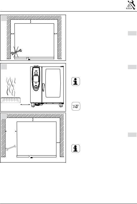
Minimum clearance left/ right/ rear 2” (50 mm) (except floor models). If on castered stand with flexible connections, that allow unit to be moved forward while still connected to gas/ele. water
pic. 1
On floor models (20x1/1 GN and 20x2/1 GN) there must be a minimum clearance of approx 20”
(500 mm) on the left side of the unit, for installing the power cable.
Minimum clearance when there are heat sources on the left-hand side is 14” (350 mm). pic 2
Attention:
A safety shut down can occur if the ambient temperature on the left hand side of the unit is too high.
 Option:
Heat shield see page 24
We recommend a distance of 500 mm (20”) on the left hand side of the unit for carrying out maintenance work. pic. 3
Attention:
-Do not install deep fat fryer at the rear of the unit.
-The units must only be installed in frost-free rooms.
- 9 - |
V-13 |
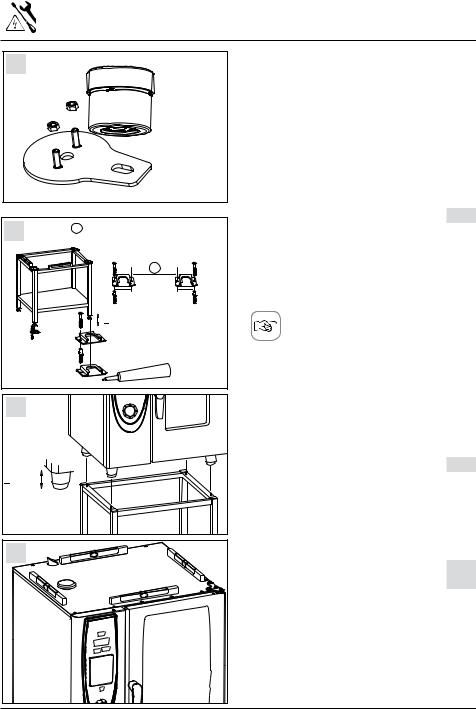
Installation type 6x1/1, 6x2/1, 10x1/1, 10x2/1 GN
1 |
|
|
Because of safety reasons table units shall only be |
|
|
|
installed on original stands of the manufacturer. |
||
|
|
|
In this case the maximum rack height is |
|
|
|
|
1600 mm (63") |
|
|
|
|
If Gas units are installed on a table or on the |
|
|
|
|
kitchen floor (combi duo) then: |
|
|
|
|
a) press the retaining plates (ET-No.:12.00.519) |
|
|
|
|
into the lower part of the pedestal and fasten |
|
|
|
|
with the enclosed nuts. |
|
|
|
|
b) the plate must be fitted to the surface using |
|
|
|
|
either screws and dowels or studs and nuts or |
|
2 |
6x2/1 10x2/1 GN: 965,5mm (38") |
the special adhesive. |
pic. 1 |
|
Retaining plates are not included in the scope |
||||
|
A 6x1/1 /10x1/1 GN: 745,5mm (29 3/8") |
|
|
|
|
|
|
of supply |
|
|
|
A |
Attention: The center height of the drain pipe is |
|
|
|
2 1/2” (63 mm). When installing combi duo |
|
|
|
|
|
|
|
|
64,5mm |
64,5mm |
observe the drain height of the bottom unit. |
|
|
|
|
||
|
2 5/8" |
2 5/8" |
|
|
|
+ 10mm |
|
|
|
|
|
|
Option: |
|
|
|
|
Using 4” (100 mm) legs and height adjust- |
|
|
|
.0213 |
able transport trolley for extended space |
|
|
|
underneath unit. See page 24 |
|
|
|
5006 |
|
||
|
|
|
||
3 |
|
|
Stands of gas appliances must be fixed to the floor |
|
|
|
|
using the fixing set part no.: 8700.0317 either with |
|
|
|
|
screws and dowels, or with the special |
|
|
|
|
adhesive supplied unless unit is connected using |
|
|
|
|
AGA/CGA approved flexible connections. |
pic. 2 |
+ 10mm |
|
|
Fixing set is not included in the scope of supply |
|
|
|
|
Slide the stand into the fixing brackets and level it. |
|
4 |
Place the unit on the stand. The feet of the unit |
|
must be secured by means of the locating pins of |
||
|
the stand |
pic. 3 |
|
Ensure that the unit is level |
pic. 4 |
|
Attention: When Installing a Combi Duo observe |
|
|
the height of the drain pipe |
|
|
. |
|
V-13 |
- 10 - |
|
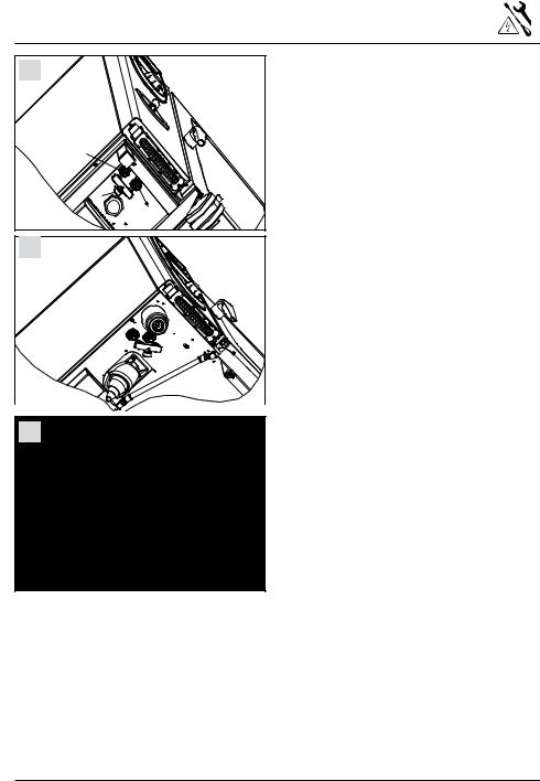
Installation type 6x1/1, 6x2/1, 10x1/1, 10x2/1 GN
1 |
2 |
3 |
Attention:
is mounted on a mobile stand or base cabinet, the unit must be additionally secured against slipping by a chain or cable in order to prevent damage to the electricity, water or gas supply line pic. 1
Only valid for SelfCooking Center with Carecontrol produced as of 28.09.2008:
At the bottom side of the SelfCooking Center a cover over the care pump is installed. This cover is secured in the upper position during transportation. If the SelfCooking Center will be installed on a table or on base cabinet then the cover must be lowered.
- Loose the screw at the front side of this cover
|
pic. 2 |
- Cover must lay on the table respectively on the |
|
top of the base cabinet. |
pic. 3 |
- 11 - |
V-13 |

Installation Type 20x1/1 GN, 20x2/1 GN
1 |
2 |
+ 10mm |
A 20x1/1 GN: 732,5 mm / 28 7/8" |
|
|
|
20x2/1 GN: 937,5 mm / 37" |
|
|
|
|
A |
|
|
64,5mm |
64,5mm |
5006. |
0213 |
|
|||
|
|
||
2 5/8" |
2 5/8" |
|
|
3 |
|
|
|
Ensure that the unit is level pic. 1
Fix the floor locks, of the supplied fixing set, to the floor with either screws and pins or with the
special adhesive. |
pic. 2 |
Next slide the unit into the floor locks |
|
pic. 2 |
|
The mobile oven rack must be level when |
|
standing inside the unit |
pic. 3 |
Attention: Observe height of the drain pipe
 Option:
Using leg extension for more space underneath unit.
Install height extension for mobile oven rack see page 25
V-13 |
- 12 - |

Levelling mobile oven racks 20x1/1 and 20x2/1 GN
1
2 |
max 4 |
3 |
If the floor is not level, an access ramp (not supplied) will be required. The incline must not exceed 4°. pic. 1,2
 Warning:
If the incline exceeds 4°, hot cooking liquid can spill out of the cooking containers. Danger of scalding!
Attention:
An incorrect levelled trolley can cause malfunction during operating the unit (e. g. during Cleanjet)
 Option:
Access ramp see page 25
If there is a drain grill in front of the floor unit, a
ramp should be placed over it to enable the |
|
mobile oven rack to be used. |
pic. 3 |
Attention:
Ensure that cover extends to left of the unit to prevent moisture (water, vapor) from entering air filter
- 13 - |
V-13 |

Electrical connection
1 |
|
5 mm |
2 |
|
|
L |
L |
|
1 |
L |
|
|
2 |
|
|
|
3 N |
3
 Attention:
Observe local regulations and standards during installation!
Common information see next page Electrical units s¬¬%ACH¬APPLIANCE¬REQUIRES¬AN¬INDEPENDENT¬FUSED¬ power supply line (common phase circuit braker) s¬¬!¬PERMANENT¬ELECTRICAL¬CONNECTION¬MUST¬BE¬PROvided for the units. s¬¬!LL¬UNITS¬ARE¬DELIVERED¬WITHOUT¬POWER¬CABLE s¬&OR¬CONNECTION¬USE¬POWER¬CORD¬.%#¬5,¬STANDARD s¬¬4HE¬MAIN¬CONTACTOR¬ TABLE¬UNITS ¬RESPECTIVELY¬THE¬ main terminals (floor models) are located in the
electrical compartment and are accessible after removing the left side panel. pic. 1/2
Gas units
s¬ ¬7E¬RECOMMEND¬AN¬INDEPENDENT¬FUSED¬POWER¬ supply line
s¬ ¬!LL¬UNITS¬ARE¬EQUIPPED¬WITH¬A¬POWER¬CABLE¬
(standard 5-15P 120V IP) with plug, approx. 8 ft (2,5 m) long
s¬¬3HOULD¬THE¬UNIT¬BE¬CONNECTED¬VIA¬A¬MAINS¬PLUG ¬ make sure it is accessible. Otherwise provide accessible all-pole disconnection device with a minimum of a 3 mm contact gap.
s¬¬!TTENTION
Observe polarity of the mains!
No burner function with wrong polarity! s¬¬#OLOUR¬CODING¬OF¬THE¬POWER¬CABLE ¬ green = earth, white = Neutral
black = Phase L1
Gas and electrical units s¬¬4HE¬STUD¬FOR¬THE¬EARTH¬BONDING¬IS¬LOCATED¬ON¬THE¬ bottom side, underneath the control panel, of the
unit. Connect the wire for the earth bonding
to this stud. pic. 3/4
4 |
Warning |
|
|
|
Observe colour coding of the wires. Wrong |
|
connection can cause electric shock |
|
Attention: |
|
Wrong connection can cause damages (e. g. fan |
|
motor) |
V-13 |
- 14 - |

Electrical connection
Voltage Conversion of electric units 208/240V units:
Units are set to 208 V ex works, but can be converted to 240 V.
To convert from 208V to 240 V proceed as follows:
-Disconnect unit from mains
-Remove left side panel.
-Set power switch S13 to desired voltage
(208 or 240 V) |
pic. 5 |
-On the control transformer change connection to the desired voltage input (208 or 240 V)
-In the starter kit of the unit there is a sticker which has to be filled in after voltage conversion. After filling it in put the sticker next to the type plate
440/480 V units
Units are set to 480 V ex works, but can be converted to 440 V.
To convert from 480V to 440 V proceed as follows:
-Disconnect unit from mains
-Remove left side panel.
-Remove adapter cable W22 from input transformer T3 and plug X72.
-Connect plug X72 to transformer T3.
- Set power input switch S 13 to 440 V |
pic. 5 |
5 |
|
S 13 |
208 V |
440 V |
|
|
480 V
240 V
Common information
s¬ ¬&OLLOW¬THE¬INSTALLATION¬INSTRUCTIONS¬AND¬THE¬ information on the rating plate when connecting the unit
s¬ ¬#OMPLY¬WITH¬ALL¬LOCAL¬REGULATIONS¬AND¬STANDARDS which must conform to national, state and local code requirements.
s¬ ¬7E¬RECOMMEND¬AN¬INDEPENDENT¬FUSED¬POWER¬ supply line for each appliance. Use of a common trip 2 pole or 3 pole circuit breaker or
3 pole fuse box with common trip is recommended to ensure safety.
s¬ ¬¬5NITS¬MUST¬BE¬CONNECTED¬TO¬AN¬EARTH¬LEAKAGE¬ circuit breaker. Consult with the NEC code for specific values according to KW of attached load for selection
s¬ .¬¬ OTE ¬CONNECTION¬TO¬A¬RESIDENTIAL¬TYPE¬'&)¬OF¬ insufficient leakage current is not advisable, random and or nuisance trips of the breaker could result
s¬ ¬/N SITE¬INSTALLATION ¬PROVIDE¬ACCESSIBLE¬ALL POLE¬ disconnection device with a minimum of a 3 mm contact gap
s¬ ¬4HE¬CIRCUIT¬DIAGRAM¬IS¬LOCATED¬ON¬THE¬INNER¬SIDE¬ of the left side panel.
s¬ 3PECIAL¬VOLTAGE¬AVAILABLE¬ON¬REQUEST s¬ ¬¬3EE¬CHART¬ON¬PAGE¬ ¬FOR¬WIRE¬SIZING ¬
s¬ !PPLICABLE¬STANDARDS ¬.&0!¬ .%#¬#3!¬# s¬ &OR¬ELECTRICAL¬CONNECTION¬DATA ¬SEE¬PAGES¬ s¬¬"EFORE¬PULLING¬OUT¬MAINS¬PLUG¬OR¬RECONNECTING¬IT¬ again be sure the unit is switched off.
For appliance connections, precise dimensions and connection points, see pages 36 and following.
Power cable : s¬¬4HE¬EXCHANGE¬OF¬THE¬POWER¬CABLE¬MAY¬ONLY¬BE¬ carried out by the service agents, qualified elec-
tricians or similar qualified personal
Electrical units s¬¬&OR¬CONNECTION¬USE¬POWER¬CORD¬.%#¬5,¬STANDARD s¬¬#ONNECT¬THE¬SUPPLY¬AS¬FOLLOWS
Grey terminal:
L1, L2, L3 (non-phase-sequence-dependent) Yellow/green terminal: Earth connection
Gas units: s¬¬)N¬CASE¬THE¬POWER¬CABLE¬HAS¬TO¬BE¬EXCHANGED¬ make sure to use one, that matches your local
standard (5-15P 120V IP)
- 15 - |
V-13 |

Water connection CareControl
6x1/1GN - 10x1/1GN E/G |
1 |
3 |
2 |
1 |
6x2/1GN - 10x2/1GN E/G |
2 |
|
1 |
3 |
|
2 |
20x1/1GN - 20x2/1GN E/G |
3 |
3 |
1 |
2 |
Legend to water connections valid for: |
pic. 1/2 |
-SelfCooking Center table units with Carecontrol manufactured as of
28.09.2008:
1 = Common water supply 3/4” cold water 30°C/86°F
In case of split water connection 2 = Cold water supply 3/4”
(for quenching and hand shower 30°C/86°F). 3 = Treated water connection 3/4”
(steam generator, moistening, cleaning, max. 60 °C/140°F).
Legend to water connections valid for: |
pic. 3 |
-SelfCooking Center table units with Carecontrol manufactured as of
28.09.2008:
1 = Common water supply 3/4” cold water 30°C/86°F
In case of split water connection 2 = Cold water supply 3/4”
(for quenching and hand shower 30°C/86°F). 3 = Treated water connection 3/4”
(steam generator, moistening, cleaning, max. 60 °C/140°F).
The appliance must be connected to the facility water supply with a supply hose that conforms to EN 61770 resp. IEC 61770 or of similar quality. The water supply hose must fulfill the local and/or hygiene requirements for hoses in drinking water systems for the respective area or municipality.
s¬¬)NSTALL¬INDIVIDUAL¬SHUT OFF¬VALVE¬FOR¬EACH¬ appliance
s¬¬¬2INSE¬THE¬WATER¬SUPPLY¬LINE¬PRIOR¬TO¬CONNECTION¬ to the unit!
s¬¬#ONNECTED¬WATER¬PRESSURE¬MUST¬BE¬IN¬THE¬RANGE¬
21,75 - 87 psi, recommended 43,5 psi
V-13 |
- 16 - |
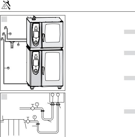
Water connection
4 |
3 |
1 |
2 |
5 |
3
 2
2  1
1
6
 2 3
2 3
1
Maximum flow rate
6x1/1, 10x 1/1: 5,3 gal/min
6x2/1, 10x2/1, 20x1/1, 20x2/1: 6,6 gal/min Average total water consumption is as follows (values excluding usage of hand shower)
6x1/1 |
6x2/1 |
10x1/1 |
10x2/1 |
20x1/1 |
20x2/1 |
3,2 |
8,5 |
6,6 |
11 |
13,1 |
15,8 |
gal/h |
gal/h |
gal/h |
gal/h |
gal/h |
gal/h |
Note:
The manufacturer recommends especially on model Combi Master a preventive check of your equipment 6 months after installation to determine actual scale build up.
This should be done by a trained technician.
s¬¬7ATER¬TREATMENT
For filter selection see pages 18/19 s¬¬4REATED¬WATER¬WITH¬A¬WATER¬HARDNESS¬LESS¬THAN¬
5 gr/gal must not be supplied, because such water can react aggressive and corrosive which can reduce the life cycle of the unit.
Connecting SelfCooking Center to water with hardness less than 7,3 gr/gal.:
To avoid an excessive build up of foam the soft water switch should be set to "ON" in the basic settings. This can be done by a trained technician.
Legend to water connections valid for: |
pic. 4-6 |
-SelfCooking Center without Carecontrol manufactured up to 27.09.2008:
-Combi Master
Floor models |
pic. 4 |
Table models electric |
|
pic. 5 |
|
Table models gas |
|
pic. 6 |
1 = Common water supply 3/4” cold water max. 30°C/86°F In case of split water connection
2= Cold water, max 30°C/86°F, connection 3/4” (quenching)
3 = Treated water connection 3/4”
(steam generator, moistening, hand shower, max 60°C/140°F)
- 17 - |
V-13 |
|
|
Selection of water filter |
|
||||
1 |
|
|
|
|
|
Please consult your local water supply |
|
|
|
|
|
|
provider for advise on chlorine (Cl2), |
|
|
|
|
|
|
|
|
chloride (Cl-) and hardness of the water. |
|
|
30C/86F |
|
|
|
A)Particle filter |
pic. 1/2 |
|
|
|
300 kPa |
|
|
|
||
|
|
|
|
|
When the water contains sand, iron particles or |
||
|
|
43,5 psi |
|
|
|
||
|
|
|
|
|
|
suspended matter, we recommend a 5-15 μm |
|
|
F |
|
|
|
|
(micro meter) particle filter: |
|
|
T |
|
|
|
|
|
|
|
I |
|
|
|
|
|
|
|
L |
300 kPa |
|
|
|
|
|
|
E |
|
|
|
|
|
|
|
R |
43,5 psi |
|
|
|
|
|
|
|
|
|
|
|
|
|
|
max. 60C/140F |
|
|
|
B) Active carbon filter |
pic. 1/2 |
|
|
|
|
|
|
|
||
30C/86F |
|
|
|
|
When the level of chlorine (Cl2) in the water |
||
|
|
|
|
exceeds 0,012 gr/gal (=0,2 ppm) (information |
|||
|
|
|
|
|
|
||
|
300 kPa |
|
|
|
available from the water company), an active car- |
||
|
|
|
|
bon filter should be installed. |
|
||
|
43,5 psi |
|
|
|
|
||
|
|
|
|
|
|
C) Complete De-Ionization |
pic. 1/2 |
|
|
|
|
|
|
When the water has a chloride Clconcentration |
|
|
|
|
|
|
|
above 4.68 gr/gal (= 80 ppm), a complete |
|
|
|
|
|
|
|
deionization system should be installed to avoid |
|
2 |
|
150-600kpa |
2 |
3 |
|
corrosion. |
|
|
|
|
|
Note: Make sure a remaining conductivity of |
|||
|
|
21,75-87 psi |
R 3/4" |
|
|
||
|
|
|
|
50 μS/cm (micro Siemens) remains in the water. |
|||
|
|
|
|
|
|||
|
|
150-600kpa |
|
|
R3/4" |
D)Water softener: |
pic. 1/2 |
3/4" |
|
|
|
|
|||
|
21,75-87 psi |
|
|
|
Valid for SelfCooking Center with |
|
|
|
|
|
|
|
|
|
|
|
|
|
|
|
|
Carecontrol: |
|
|
|
1/2" |
|
1/2" |
|
These models will remove scale all by itself pro- |
|
|
|
|
|||
|
|
|
|
|
||
|
|
|
|
|||
|
|
|
|
|
viding that the units are used as prescribed. |
|
|
A B C D |
3/4" |
|
max. 60°C |
|
|
|
|
|
These means a water softener is not needed. |
|||
|
|
|
max. 140°F |
|
||
|
|
|
|
|
Valid for SelfCooking Center without |
|
|
|
|
|
|
||
|
|
|
|
|
|
|
|
|
|
|
|
|
|
|
|
|
|
|
|
Carecontrol and Combi Master: |
|
|
|
|
|
|
A water softener is recommended when a high |
|
|
|
|
|
|
level of scale (not containing chloride) is |
|
|
|
|
|
|
experienced. Systems recommended: H+ Ion |
|
|
|
|
|
|
Exchanger or Kleensteam. Sodium ion |
|
|
|
|
|
|
exchangers (as used in dishwashers) must not |
|
|
|
|
|
|
be used. |
|
|
|
|
|
|
Treated water with a water hardness less than5 |
|
|
|
|
|
|
gr/gal must not be supplied, because such water |
|
|
|
|
|
|
can react aggressive and corrosive which can |
|
|
|
|
|
|
reduce the life cycle of the unit. |
|
|
|
|
|
|
Amongst others the following filter manufacturers |
|
|
|
|
|
|
offer adequate filter applications: |
|
|
|
|
|
|
Britta, Cuno, Everpure, Selecto, Scientific |
|
|
|
|
|
|
|
V-13 |
|
|
|
- 18 - |
||
 Loading...