

Ransburg RansFlex RX 80345, RansFlex RFX 80365 Service Manual

SERVICE MANUAL
AH-15-01.2
JULY - 2015
®
By Ransburg
APPLICATORS
MODEL: 80345 AND 80365 RX & RFX
IMPORTANT: Before using this equipment, carefully read SAFETY
PRECAUTIONS, starting on page 1, and all instructions in this manual.
Keep this Service Manual for future reference.
Service Manual Price: $50.00 (U.S.)

Ranex Applicators - REVISIONS
NOTE: This manual has been changed from revision AH-15-01 to revision
AH-15-01.2. Reasons for this change are noted under “Manual Change
Summary” on page 57 of this manual.
AH-15-01.2

Ranex Applicators - CONTENTS
CONTENTS
PAGE
SAFETY: 1-5
Safety Precautions .............................................................................................................................. 1
Hazards / Safegaurds ........................................................................................................................... 2
ATEX/FM: 6-13
European Atex Directive ...................................................................................................................... 6
European Atex Labels .......................................................................................................................... 7
FM Conguration Drawings 80345 ....................................................................................................... 8
FM Conguration Drawings 80365 ....................................................................................................... 11
INTRODUCTION: 14-18
General Description ............................................................................................................................. 14
Ransex New Features .......................................................................................................................14
Specications 80345 ...........................................................................................................................15
Specications 80365 ...........................................................................................................................16
Ransex Solventborne Electrostatic Spray Applicator 80345 / 80365 ................................................17
Typical Solvenborne Installation ...........................................................................................................18
INSTALLATION: 19-20
80345/80365 Ransex Solventborne Installation ................................................................................ 19
General Installation Requirements .......................................................................................................19
Installation ............................................................................................................................................20
OPERATION: 21-27
Applicator Operation ............................................................................................................................ 21
Flushing / Color Change Procedure ..................................................................................................... 23
Fluid Nozzle / Air Cap ........................................................................................................................... 24
New Nozzle Design .............................................................................................................................. 24
Nozzle Selection ................................................................................................................................... 25
Air Cap / Nozzle Performance .............................................................................................................. 27
MAINTENANCE: 28-41
Routine Schedule ................................................................................................................................ 28-40
Troubleshooting Guide ......................................................................................................................... 41
PARTS IDENTIFICATION: 42-58
Ransex RX Solvent Base .................................................................................................................. 42
Ransex RFX Solvent Base ................................................................................................................. 44
Items for RX (45KV) Unit ...................................................................................................................... 46
Items for RX (65KV) Unit ...................................................................................................................... 48
Components For All Models ................................................................................................................. 50
Accessories / Spare Parts Kits ............................................................................................................. 57
Recommended Spare Parts ................................................................................................................. 58
WARRANTY POLICIES: 59
Limited Warranty ................................................................................................................................. 59
AH-15-01.2
SAFETY
SAFETY PRECAUTIONS
Before operating, maintaining or servicing any Ransburg
electrostatic coating system, read and understand all
of the technical and safety literature for your Ransburg
products. This manual contains information that is
important for you to know and understand. This
information relates to USER SAFETY and PREVENTING
EQUIPMENT PROBLEMS. To help you recognize this
information, we use the following symbols. Please pay
particular attention to these sections.
A WARNING! states information to alert you to
a situation that might cause serious injury if
instructions are not followed.
A CAUTION! states information that tells how to
prevent damage to equipment or how to avoid a
situation that might cause minor injury.
Ranex Applicators - SAFETY
W A R N I N G
!
The user MUST read and be familiar with the
Safety Section in this manual and the Ransburg
safety literature therein identied.
This manual MUST be read and thoroughly
understood by ALL personnel who operate, clean
or maintain this equipment! Special care should be
taken to ensure that the WARNINGS and safety
requirements for operating and servicing the
equipment are followed. The user should be aware
of and adhere to ALL local building and re codes
and ordinances as well as NFPA-33 SAFETY
STANDARD, LATEST EDITION, prior to installing,
operating, and/or servicing this equipment.
A NOTE is information relevant to the procedure
in progress.
While this manual lists standard specications and
service procedures, some minor deviations may be
found between this literature and your equipment.
Dierences in local codes and plant requirements,
material delivery requirements, etc., make such
variations inevitable. Compare this manual with your
system installation drawings and appropriate Ransburg
equipment manuals to reconcile such dierences.
Careful study and continued use of this manual will
provide a better understanding of the equipment and
process, resulting in more ecient operation, longer
trouble-free service and faster, easier troubleshooting.
If you do not have the manuals and safety literature for
your Ransburg system, contact your local Ransburg
representative or Ransburg.
W A R N I N G
!
The hazards shown on the following pages
may occur during the normal use of this equipment.
Please read the hazard chart beginning on page 2.
AH-15-01.2
Return To Contents
1

Ranex Applicators - SAFETY
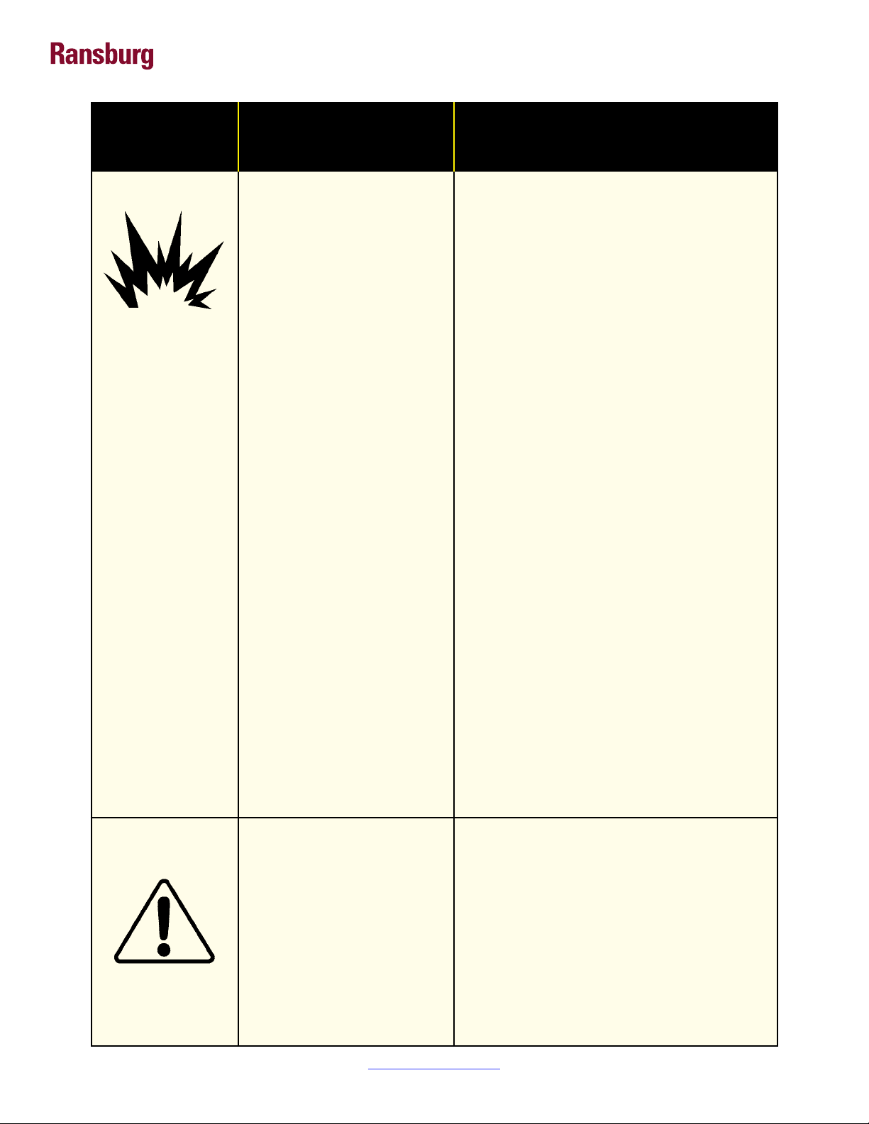
AREA
Tells where hazards
may occur.
Spray Area
HAZARD
Tells what the hazard is.
Fire Hazard
Improper or inadequate
operation and maintenance
procedures will cause a re
hazard.
Protection against inadvertent
arcing that is capable of
causing re or explosion is lost
if any safety interlocks are
disabled during operation.
Frequent Power Supply or
Controller shutdown indicates
a problem in the system
requiring correction.
SAFEGUARDS
Tells how to avoid the hazard.
Fire extinguishing equipment must be present in
the spray area and tested periodically.
Spray areas must be kept clean to prevent the
accumulation of combustible residues.
Smoking must never be allowed in the spray area.
The high voltage supplied to the atomizer must be
turned off prior to cleaning, ushing or maintenance.
When using solvents for cleaning:
• Those used for equipment ushing should
have ash points equal to or higher than those
of the coating material.
• The ash point of the cleaning solvent shall
be at least 15° C (27° F) above the ambient
temperature. Otherwise, the cleaning process
must be carried out in an area with forced air
ventilation. It is the end users responsibility to
insure this condition is met.
Spray booth ventilation must be kept at the
rates required by NFPA-33, OSHA, country, and
local codes. In addition, ventilation must be
maintained during cleaning operations using
ammable or combustible solvents.
Electrostatic arcing must be prevented. Safe
sparking distance must be maintained between
the parts being coated and the applicator. A
distance of 1 inch for every 10KV of output
voltage is required at all times.
Test only in areas free of combustible material.
Testing may require high voltage to be on, but
only as instructed.
Non-factory replacement parts or
unauthorized equipment modications may
cause re or injury.
If used, the key switch bypass is intended for use
only during setup operations. Production should
never be done with safety interlocks disabled.
Never use equipment intended for use in
waterborne installations to spray solvent based
materials.
AH-15-01.2
The paint process and equipment should be
set up and operated in accordance with NFPA33, NEC, OSHA, local, country, and European
Health and Safety Norms.
Return To Contents
2
Ranex Applicators - SAFETY
AREA
Tells where hazards
may occur.
Spray Area
HAZARD
Tells what the hazard is.
Explosion Hazard
Improper or inadequate operation and maintenance proce-
dures will cause a re hazard.
Protection against inadvertent
arcing that is capable of caus-
ing re or explosion is lost if
any safety interlocks are disabled during operation.
Frequent Power Supply or
Controller shutdown indicates
a problem in the system requiring correction.
SAFEGUARDS
Tells how to avoid the hazard.
Electrostatic arcing must be prevented. Safe
sparking distance must be maintained between
the parts being coated and the applicator. A dis-
tance of 1 inch for every 10KV of output voltage
is required at all times.
Unless specically approved for use in hazardous locations, all electrical equipment must be
located outside Class I or II, Division 1 or 2
hazardous areas, in accordance with NFPA-33.
Test only in areas free of ammable or combus-
tible materials.
The current overload sensitivity (if equipped)
MUST be set as described in the corresponding section of the equipment manual. Protection against inadvertent arcing that is capable
of causing re or explosion is lost if the current
overload sensitivity is not properly set. Fre-
quent power supply shutdown indicates a problem in the system which requires correction.
General Use and
Maintenance
Improper operation or maintenance may create a hazard.
Personnel must be properly
trained in the use of this equipment.
Always turn the control panel power off prior to
ushing, cleaning, or working on spray system
equipment.
Before turning high voltage on, make sure no
objects are within the safe sparking distance.
Ensure that the control panel is interlocked with
the ventilation system and conveyor in accor-
dance with NFPA-33, EN 50176.
Have re extinguishing equipment readily avail-
able and tested periodically.
Personnel must be given training in accordance
with the requirements of NFPA-33, EN 60079-0.
Instructions and safety precautions must be
read and understood prior to using this equipment.
Comply with appropriate local, state, and national codes governing ventilation, re protec-
tion, operation maintenance, and housekeep-
ing. Reference OSHA, NFPA-33, EN Norms
and your insurance company requirements.
AH-15-01.2
Return To Contents
3

Ranex Applicators - SAFETY
AREA
Tells where hazards
may occur.
Spray Area /
High Voltage
Equipment
HAZARD
Tells what the hazard is.
Electrical Discharge
There is a high voltage device
that can induce an electrical
charge on ungrounded objects
which is capable of igniting
coating materials.
Inadequate grounding will
cause a spark hazard. A
spark can ignite many coating
materials and cause a re or
explosion.
SAFEGUARDS
Tells how to avoid the hazard.
Parts being sprayed and operators in the spray
area must be properly grounded.
Parts being sprayed must be supported on conveyors or hangers that are properly ground-
ed. The resistance between the part and earth
ground must not exceed 1 meg ohm. (Refer to
NFPA-33.)
Operators must be grounded. Rubber soled in-
sulating shoes should not be worn. Grounding
straps on wrists or legs may be used to assure
adequate ground contact.
Operators must not be wearing or carrying any
ungrounded metal objects.
When using an electrostatic handgun, operators
must assure contact with the handle of the applicator via conductive gloves or gloves with the
palm section cut out.
NOTE: REFER TO NFPA-33 OR SPECIFIC
COUNTRY SAFETY CODES REGARDING
PROPER OPERATOR GROUNDING.
All electrically conductive objects in the spray
area, with the exception of those objects re-
quired by the process to be at high voltage, must
be grounded. Grounded conductive ooring
must be provided in the spray area.
Always turn off the power supply prior to ushing, cleaning, or working on spray system equip-
ment.
Unless specically approved for use in hazardous locations, all electrical equipment must be
located outside Class I or II, Division 1 or 2 haz-
ardous areas, in accordance with NFPA-33.
AH-15-01.2
Return To Contents
4

Ranex Applicators - SAFETY
AREA
Tells where hazards
may occur.
Electrical
Equipment
HAZARD
Tells what the hazard is.
Electrical Discharge
High voltage equipment is
utilized in the process. Arcing
in the vicinity of ammable or
combustible materials may
occur. Personnel are exposed
to high voltage during operation
and maintenance.
Protection against inadvertent
arcing that may cause a re or
explosion is lost if safety circuits
are disabled during operation.
Frequent power supply shutdown indicates a problem in
the system which requires
correction.
An electrical arc can ignite
coating materials and cause a
re or explosion.
SAFEGUARDS
Tells how to avoid the hazard.
Unless specically approved for use in hazardous locations, the power supply, control cabi-
net, and all other electrical equipment must be
located outside Class I or II, Division 1 and 2
hazardous areas in accordance with NFPA-33
and EN 50176.
Turn the power supply OFF before working on
the equipment.
Test only in areas free of ammable or combustible material.
Testing may require high voltage to be on, but
only as instructed.
Production should never be done with the safety circuits disabled.
Before turning the high voltage on, make sure
no objects are within the sparking distance.
Toxic
Substances
Spray Area
Certain material may be harmful
if inhaled, or if there is contact
with the skin.
Explosion Hazard –
Incompatible Materials
Halogenated hydrocarbon
solvents for example:
methylene chloride and
1,1,1,-Trichloroethane are not
chemically compatible with the
aluminum that might be used
in many system components.
The chemical reaction caused
by these solvents reacting with
aluminum can become violent
and lead to an equipment
explosion.
Follow the requirements of the Material Safety
Data Sheet supplied by coating material
manufacturer.
Adequate exhaust must be provided to keep the
air free of accumulations of toxic materials.
Use a mask or respirator whenever there is
a chance of inhaling sprayed materials. The
mask must be compatible with the material
being sprayed and its concentration. Equipment
must be as prescribed by an industrial hygienist
or safety expert, and be NIOSH approved.
Aluminum is widely used in other spray appli-
cation equipment - such as material pumps,
regulators, triggering valves, etc. Halogenated
hydrocarbon solvents must never be used with
aluminum equipment during spraying, ushing,
or cleaning. Read the label or data sheet for
the material you intend to spray. If in doubt as
to whether or not a coating or cleaning material
is compatible, contact your coating supplier.
Any other type of solvent may be used with
aluminum equipment.
AH-15-01.2
Return To Contents
5

Ranex Applicators - ATEX
EUROPEAN ATEX DIRECTIVE 94/9/EC, ANNEX II, 1.0.6
The following instructions apply to equipment covered
by certicate number Sira 14ATEX5343:
1. The equipment may be used with ammable
gases and vapors with apparatus groups II and
with temperature class T6.
2.
The equipment is only certied for use in ambient
temperatures in the range 5°C to +40°C and should
not be used outside this range.
3.
Installation shall be carried out by suitably trained
personnel in accordance with the applicable code
of practice e.g. EN 60079-14:1997.
4. Inspection and maintenance of this equipment
shall be carried out by suitably trained personnel
in accordance with the applicable code of practice
e.g. EN 60079-17.
5.
Repair of this equipment shall be carried out
by suitable trained personnel in accordance
with the applicable code of practice e.g. EN
60079-19.
6. Putting into service, use, assembling, and
adjustment of the equipment shall be tted by
suitably trained personnel in accordance with the
manufacturer's documentation.
of the user to take suitable precautions that prevent
it from being adversely affected, thus ensuring that
the type of protection provided by the equipment
is not compromised.
Aggressive substances: e.g. acidic liquids or gases
that may attack metals, or solvents that may affect
polymeric materials.
Suitable precautions: e.g. regular checks as part
of routine inspections or establishing from the
material's data sheets that it is resistant to specic
chemicals.
Refer to "Specications" in the "Introduction"
section:
a. All uid passages contain stainless steel or
nylon ttings.
b. High voltage cascade is encapsulated with a
solvent resistant epoxy.
9.
A recapitulation of the certication marking is
detailed in the "ATEX" section, on the next page,
drawing numbers: 80277-01, 02, 03 and 04.
10.
The characteristics of the equipment shall be
detailed e.g. electrical, pressure, and voltage
parameters.
Refer to the "Table of Contents" of this service
manual:
a. Installation
b. Operation
c. Maintenance
d. Parts Identication
7. Components to be incorporated into or used as
replacement parts of the equipment shall be tted
by suitably trained personnel in accordance with
the manufacturer's documentation.
8. The certication of this equipment relies upon the
following materials used in its construction:
If the equipment is likely to come into contact with
aggressive substances, then it is the responsibility
AH-15-01.2
The manufacturer should note that, on being put
into service, the equipment must be accompanied
by a translation of the instructions in the language
or languages of the country in which the equipment
is to be used and by the instructions in the original
language.
Return To Contents
6
Ransex 80345/80365 ATEX
Product Marking Denitions
Ex Certicate Number: Sira 14ATEX5343
Ranex Applicators - ATEX
®
Sira = Notied Body performing EC-type
examination
14 = Year of certication
ATEX = Reference to ATEX Directive
5 = Protection Concept Code (code 5 is
titled Encapsulation)
343 = Document serial number
X = Special conditions for safe use apply
Special conditions for safe use:
The Ransex 80345/80365 Applicators shall only be
used with associated Ransburg 79727-XX Air Hose
Assembly. It is the end users responsibility to insure
the air hose is properly grounded to true earth ground.
Resistance of this air hose assembly must be .5 MW
or less reguardless of hose length.
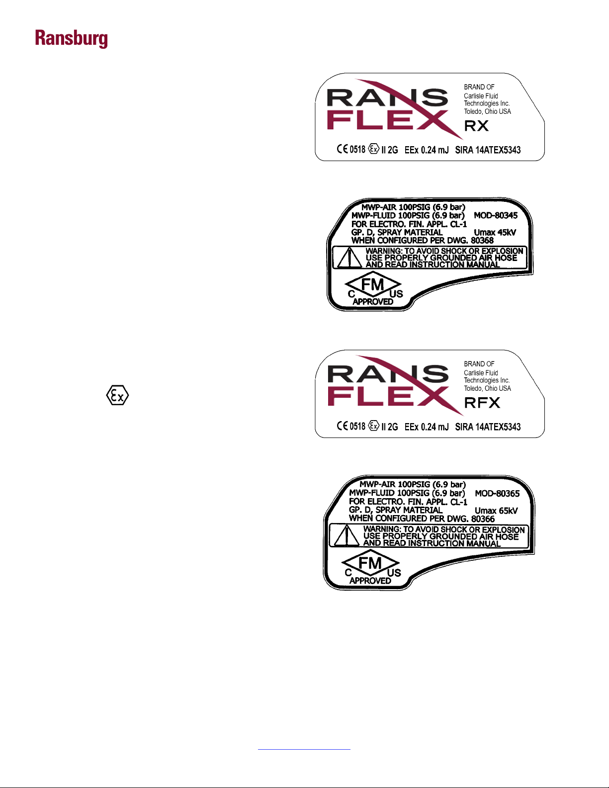
Product Marking
II 2 G
Ex = Specic marking of explosive protection
By Ransburg
Label 80277-04
Label 80277-03
®
By Ransburg
II = Equipment Group hazardous area
characteristics
2 = Equipment Category
G = Type of explosive atmosphere (gases,
vapors, or mists)
EEx 0.24mJ = The Ransex 80345/80365 Applicators
are suitable for use in manual spraying installations
complying with EN 50 050 as they are a Type A class
with a discharge energy limit of 0.24mJ.
Label 80277-02
Label 80277-01
FM Conguration
These applicators are FM approved when the setup is
congured to drawings shown on pages 8, 9, 10 and 11.
AH-15-01.2
Return To Contents
7

Ranex Applicators - ATEX
RANSFLEX RX - SOLVENT BASE
80345 -
Base
Model No.
ABCDEF
Optional
Designations
(Ordering Information Only)
A
C
B
D
F
E
CONFIGURATION DWG. 80368
REV. A
AH-15-01.2
Return To Contents
8

Ranex Applicators - ATEX
“S” (Fluid Nozzle)“R” (Air Cap)
“T” (Pressure Reducer)
ATOMIZATION - TABLE OF “A” DASHES
“A” Dash No.
“A” Description
“R”
0 V SERIES 1.2mm 80265-00 80264-12 79809-00
1 V SERIES 1.4mm 80265-00 80264-14 79809-00
2 V SERIES 1.8mm 80265-00 80264-18 79809-00
3 C SERIES 1.2mm 80231-00 80230-12 79809-03
4 C SERIES 1.4mm 80231-00 80230-14 79809-03
5 C SERIES 1.8mm 80231-00 80230-18 79809-03
6 T SERIES 1.2mm 80240-00 80239-12 74963-05
7 T SERIES 1.4mm 80240-00 80239-14 74963-05
8 T SERIES 1.8mm 80240-00 80239-18 74963-05
9 ROUND SPRAY 79962-00 80400-00 74963-05
80262-01 “U” 80262-00 “U”
“S”
“T”
FLUID CONTROL - TABLE OF “B” DASHES
“B” Dash No.
1 ADJUSTABLE FLUID 80262-00
2 NON-ADJUSTABLE FLUID 80262-01
80211-00 “V”
“B” Description
TRIGGER - TABLE OF “C” DASHES
“C” Dash No.
1 2 FINGER TRIGGER 80211-00
2 4 FINGER TRIGGER 80386-00*
“C” Description
“U”
“V”
* Available after August 1, 2015
AH-15-01.2
Return To Contents
9

Ranex Applicators - ATEX
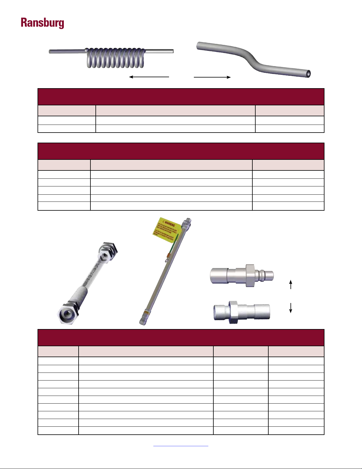
79879-01
“W”
80269-45
FLUID INLET - TABLE OF “D” DASHES
“D” Dash No.
1 STD FLUID INLET TUBE 80269-45
2 COILED FLUID INLET TUBE 79879-01
“D” Description
FLUID HOSE - TABLE OF “E” DASHES
“E” Dash No.
0 NO FLUID HOSE ---
1 FLUID HOSE, 10m 80303-10
2 FLUID HOSE, 15m 80303-15
3 FLUID HOSE, 20m 80303-20
4 FLUID HOSE, 30m 80303-30
“E” Description
“W”
“X”
AH-15-01.2
80303-XX “X” 79727-XX “Y”
AIR HOSE - TABLE OF “F” DASHES
“F” Dash No.
0 NO AIR HOSE, STANDARD --- 80236-00
1 STANDARD AIR HOSE, 10m 79727-10 80236-00
2 STANDARD AIR HOSE, 15m 79727-15 80236-00
3 STANDARD AIR HOSE, 20m 79727-20 80236-00
4 STANDARD AIR HOSE, 30m 79727-30 80236-00
5 NO AIR HOSE, QD --- 80302-00
6 QD AIR HOSE, 10m 79727-11 80302-00
7 QD AIR HOSE, 15m 79727-16 80302-00
8 QD AIR HOSE, 20m 79727-21 80302-00
9 QD AIR HOSE, 30m 79727-31 80302-00
“F” Description
Return To Contents
80302-00
“Z”
80236-00
“Z”“Y”
10

Ranex Applicators - ATEX
RANSFLEX RFX - SOLVENT BASE
80365 -
Base
Model No.
ABCDEF
Optional
Designations
(Ordering Information Only)
A
C
B
D
F
E
CONFIGURATION DWG. 80366
REV. A
AH-15-01.2
Return To Contents
11

Ranex Applicators - ATEX
“S” (Fluid Nozzle)“R” (Air Cap)
“T” (Pressure Reducer)
ATOMIZATION - TABLE OF “A” DASHES
“A” Dash No.
“A” Description
“R”
“S”
0 V SERIES 1.2mm 80265-00 80264-12 79809-00
1 V SERIES 1.4mm 80265-00 80264-14 79809-00
2 V SERIES 1.8mm 80265-00 80264-18 79809-00
3 C SERIES 1.2mm 80231-00 80230-12 79809-03
4 C SERIES 1.4mm 80231-00 80230-14 79809-03
5 C SERIES 1.8mm 80231-00 80230-18 79809-03
6 T SERIES 1.2mm 80240-00 80239-12 74963-05
7 T SERIES 1.4mm 80240-00 80239-14 74963-05
8 T SERIES 1.8mm 80240-00 80239-18 74963-05
9 ROUND SPRAY 79962-00 80400-00 74963-05
80262-01 “U” 80262-00 “U”
“T”
FLUID CONTROL - TABLE OF “B” DASHES
“B” Dash No.
1 ADJUSTABLE FLUID 80262-00
2 NON-ADJUSTABLE FLUID 80262-01
80211-00 “V”
“B” Description
TRIGGER - TABLE OF “C” DASHES
“C” Dash No.
1 2 FINGER TRIGGER 80211-00
2 4 FINGER TRIGGER 80386-00*
“C” Description
“U”
“V”
* Available after August 1, 2015
AH-15-01.2
Return To Contents
12
Ranex Applicators - ATEX
79879-01
“W”
80269-45
FLUID INLET - TABLE OF “D” DASHES
“D” Dash No.
1 STD FLUID INLET TUBE 80269-45
2 COILED FLUID INLET TUBE 79879-01
“D” Description
FLUID HOSE - TABLE OF “E” DASHES
“E” Dash No.
0 NO FLUID HOSE ---
1 FLUID HOSE, 10m 80303-10
2 FLUID HOSE, 15m 80303-15
3 FLUID HOSE, 20m 80303-20
4 FLUID HOSE, 30m 80303-30
“E” Description
“W”
“W”
AH-15-01.2
80303-XX “X” 79727-XX “Y”
AIR HOSE - TABLE OF “F” DASHES
“F” Dash No.
0 NO AIR HOSE, STANDARD --- 80236-00
1 STANDARD AIR HOSE, 10m 79727-10 80236-00
2 STANDARD AIR HOSE, 15m 79727-15 80236-00
3 STANDARD AIR HOSE, 20m 79727-20 80236-00
4 STANDARD AIR HOSE, 30m 79727-30 80236-00
5 NO AIR HOSE, QD --- 80302-00
6 QD AIR HOSE, 10m 79727-11 80302-00
7 QD AIR HOSE, 15m 79727-16 80302-00
8 QD AIR HOSE, 20m 79727-21 80302-00
9 QD AIR HOSE, 30m 79727-31 80302-00
“F” Description
Return To Contents
80302-00
“Z”
80236-00
“Z”“Y”
13

INTRODUCTION
Ranex Applicators - INTRODUCTION
GENERAL DESCRIPTION
The Ransex is an air atomizing applicator powered
only by a pressurized air source. Pressurized air creates
rotation of a turbine generator that powers a cascade.
The cascade generates a high voltage DC charge to
the electrode creating an electrostatic eld between
the atomizer and the target.
One of the many features of the Ransex applicator
system is that the electrical energy, which is available
from the resistive charging electrode, is limited to the
optimum level of safety and efciency. The system is
incapable of releasing sufcient electrical or thermal
energy during normal operating conditions to cause
ignition of specic hazardous materials in their most
easily ignited concentrations in air.
As the applicator electrode approaches ground,
applicator circuitry causes the high voltage to approach
zero while the current approaches its maximum value.
This performance is validated by independent test
agencies that give FM US&C and ATEX EN 50 050.
RANSFLEX NEW FEATURES
• Light weight and easy to maneuver.
• Ergonomic handle design to reduce
operator fatigue.
• Three phases of turbine protection:
- Divorced turbine air supply cartridge
- Sealed nozzle/Atomization passages
- Strategic turbine location
• DeVilbiss spray technology integration
into atomization.
• Simultaneous fan/atom pressure adjustment with
compensation valve.
AH-15-01.2
Return To Contents
14

Ranex Applicators - INTRODUCTION
80345 RANSFLEX SOLVENTBORNE
SPECIFICATIONS
Environmental/Physical
Applicator Length: 254mm (10-inches)
Weight: (Without Hose) 600 grams (21.3 oz.)
Hose 79727-XX Lengths (Std): 10m, 15m, 20m, and 30m
Electrical
Operating Voltage: 45kV DC (-) maximum
Current Output: 140 microamperes maximum
Paint Resistance:* .1 MW to ∞
Part Sprayability: Determine sprayability of part to be coated using 76652, Test Equipment
(See current “Paint, HV & SCI Test Equipment” service manual TE-98-01)
* Use Model No. 76652, Test Equipment
Mechanical
Fluid Flow Capacity: 1000 ml/minute**
Wetted Parts: Stainless, polyethylene, nylon, acetal polymer
Operating Pressure (Air Spray)
Fluid: (0-6.9 bar) 0-100 psi
Air: (0-6.9 bar) 0-100 psi
Ambient Temp.: 40°C to 5°C (104°F to 32°F)
Consumption (With Voltage): 438 SLPM (15.4 SCFM) @ 2.8 bar (40 psig) @ Handle Inlet
Sound Level: 92dB (A) @ 2.8 bar (40 psig) Inlet, 1m from applicator
** This reects the maximum uid volume the applicator can deliver. The maximum spray volume that can be effectively
atomized depends on uid rheology, spray technology, and nish quality required.
AH-15-01.2
Return To Contents
15

Ranex Applicators - INTRODUCTION
80365 RANSFLEX SOLVENTBORNE
SPECIFICATIONS
Environmental/Physical
Applicator Length: 273mm (10.75-inches)
Weight: (Without Hose) 620 grams (22 oz.)
Hose 79727-XX Lengths (Std): 10m, 15m, 20m, and 30m
Electrical
Operating Voltage: 65kV DC (-) maximum
Current Output: 120 microamperes maximum
Paint Resistance:* .1 MW to ∞
Part Sprayability: Determine sprayability of part to be coated using 76652, Test Equipment
(See current “Paint, HV & SCI Test Equipment” service manual TE-98-01)
* Use Model No. 76652, Test Equipment
Mechanical
Fluid Flow Capacity: 1000 ml/minute**
Wetted Parts: Stainless, polyethylene, nylon, acetal polymer
Operating Pressure (Air Spray)
Fluid: (0-6.9 bar) 0-100 psi
Air: (0-6.9 bar) 0-100 psi
Ambient Temp.: 40°C to 5°C (104°F to 32°F)
Consumption (With Voltage): 438 SLPM (15.4 SCFM) @ 2.8 bar (40 psig) @ Handle Inlet
Sound Level: 92dB (A) @ 2.8 bar (40 psig) Inlet, 1m from applicator
** This reects the maximum uid volume the applicator can deliver. The maximum spray volume that can be effectively
atomized depends on uid rheology, spray technology, and nish quality required.
AH-15-01.2
Return To Contents
16

Ranex Applicators - INTRODUCTION
11
9
4
5
3
2
1
10
7
6
8
Figure 1: Ransex Solventborne Electrostatic Spray Applicator 80345 / 80365
RANSFLEX SOLVENTBORNE ELECTROSTATIC
SPRAY APPLICATOR 80345 / 80365
12
AH-15-01.2
No.
1 Needle/Electrode
2 Barrel
3 Handle
4 Fan Adjustment
5 Fluid Adjustment
6 Air Hose
Description
No.
7 Exhaust Air Hose
8 Fluid Hose
9 Voltage On/Off Switch
10 Trigger
11 Compensation Valve
12 Air Cap / Fluid Nozzle
Return To Contents
Description
17
 Loading...