

Ransburg RANSFLEX 81520 RFXw, RansFlex, RansFlex RFXW, Ranflex 81345 RX, Ranflex 81365 RX Service Manual
...
SERVICE MANUAL
AH-17-04-R0.0
®
By Ransburg
APPLICATORS
FOR DIRECT CHARGE
WATER BASED APPLICATORS
MODEL: 81520 RFXw
IMPORTANT: Before using this equipment, carefully read SAFETY PRECAUTIONS, starting on
page 3, and all instructions in this manual. Keep this Service Manual for future reference.
AH-17-04-R0.0 (11/2017) 1 / 59 www.carlisleft.com

CONTENTS
CONTENTS
SAFETY: 3-7
Safety Precautions ................................................................................................................................................3
Hazards / Safegaurds ............................................................................................................................................4
ATEX/FM REQUIREMENTS: 8-13
European ATEX Directive ...................................................................................................................................... 8
ATEX and FM Requirments ....................................................................................................................................9
RansFlex RFXw - Water Base Only .....................................................................................................................10
INTRODUCTION: 14-17
General Description .............................................................................................................................................14
Ransex New Features .......................................................................................................................................14
Specications ......................................................................................................................................................15
Typical Installation ...............................................................................................................................................17
INSTALLATION: 18-20
81520 Ransex Direct Charge Installation ..........................................................................................................18
General Installation Requirements ......................................................................................................................18
Waterborne Isolation System Installation Guidelines ...........................................................................................19
Applicator Installation ...........................................................................................................................................19
OPERATION: 21-27
Applicator Operation ............................................................................................................................................21
Flushing / Color Change Procedure ....................................................................................................................23
Fluid Nozzle / Air Cap ..........................................................................................................................................24
New Nozzle Design .............................................................................................................................................24
Air Cap / Nozzle Performance .............................................................................................................................27
MAINTENANCE: 28-42
Suitable Solvents For Cleaning RansFlex Applicators ........................................................................................28
Routine Schedule ................................................................................................................................................29
Troubleshooting Guide ........................................................................................................................................42
PARTS IDENTIFICATION: 43-58
RansFlex RFXw Direct Charge Water Base ........................................................................................................43
Items for RFXw (65KV) Unit ................................................................................................................................46
Handle Components For All Models ....................................................................................................................48
Accessories .........................................................................................................................................................56
Spare Parts Kits ...................................................................................................................................................57
Recommended Spare Parts ................................................................................................................................58
AH-17-04-R0.0 (11/2017) 2 / 59 www.carlisleft.com
Return To Contents
SAFETY PRECAUTIONS
SAFETY
SAFETY
Before operating, maintaining or servicing any
electrostatic coating system
technical and safety literature for your Ransburg products.
This manual contains information that is important for you
to know and understand. This information relates to USER
SAFETY and PREVENTING EQUIPMENT PROBLEMS.
To help you recognize this information, we use the following
symbols. Please pay particular attention to these sections.
!
A WARNING! states information to alert you to
a situation that might cause serious injury if
instructions are not followed.
!
A CAUTION! states information that tells how to
prevent damage to equipment or how to avoid a
situation that might cause minor injury.
, read and understand all of the
WARNING
CAUTION
Ransburg
WARNING
!
The user MUST read and be familiar with the
Safety Section in this manual and the Ransburg
safety literature therein identied.
This equipment is intended to be used by
trained personnel ONLY.
This manual MUST be read and thoroughly
understood by ALL personnel who operate, clean
or maintain this equipment! Special care should be
taken to ensure that the WARNINGS and safety
requirements for operating and servicing the
equipment are followed. The user should be aware
of and adhere to ALL local building and re codes
and ordinances as well as NFPA-33 AND EN 50176
SAFETY STANDARDS, LATEST EDITION, or
applicable country safety standards, prior to installing,
operating, and/or servicing this equipment.
WARNING
!
NOTE
A NOTE is information relevant to the procedure
in progress.
While this manual lists standard specications and service
procedures, some minor deviations may be found between
this literature and your equipment. Differences in local codes
and plant requirements, material delivery requirements, etc.,
make such variations inevitable. Compare this manual with
your system installation drawings and appropriate Ransburg
equipment manuals to reconcile such differences.
Careful study and continued use of this manual will provide a
better understanding of the equipment and process, resulting
in more efcient operation, longer trouble-free service and
faster, easier troubleshooting. If you do not have the manuals
and safety literature for your Ransburg system, contact your
local Ransburg representative or Ransburg.
The hazards shown on the following pages may
occur during the normal use of this equipment. Please
read the hazard chart beginning on page 2.
AH-17-04-R0.0 (11/2017) 3 / 59 www.carlisleft.com

Return To Contents
SAFETY
AREA
Tells where hazards
may occur.
Spray Area
HAZARD
Tells what the hazard is.
Fire Hazard
Improper or inadequate
operation and maintenance
procedures will cause a re
hazard.
Protection against inadvertent
arcing that is capable of
causing re or explosion is lost
if any safety interlocks are
disabled during operation.
Frequent Power Supply or
Controller shutdown indicates
a problem in the system
requiring correction.
SAFEGUARDS
Tells how to avoid the hazard.
Fire extinguishing equipment must be present in the
spray area and tested periodically.
Spray areas must be kept clean to prevent the
accumulation of combustible residues.
Smoking must never be allowed in the spray area.
The high voltage supplied to the atomizer must be
turned off prior to cleaning, ushing or maintenance.
Spray booth ventilation must be kept at the rates
required by NFPA-33, OSHA, country, and local
codes. In addition, ventilation must be maintained
during cleaning operations using ammable or
combustible solvents.
Electrostatic arcing must be prevented. Safe
sparking distance must be maintained between the
parts being coated and the applicator. A distance of
1 inch for every 10KV of output voltage is required
at all times.
Test only in areas free of combustible material.
Testing may require high voltage to be on, but only
as instructed.
Non-factory replacement parts or unauthorized
equipment modications may cause re or injury.
If used, the key switch bypass is intended for use
only during setup operations. Production should
never be done with safety interlocks disabled.
The paint process and equipment should be set up
and operated in accordance with NFPA-33, NEC,
OSHA, local, country, and European Health and
Safety Norms.
AH-17-04-R0.0 (11/2017) 4 / 59 www.carlisleft.com

Return To Contents
SAFETY
AREA
Tells where hazards
may occur.
Spray Area
HAZARD
Tells what the hazard is.
Explosion Hazard
Improper or inadequate
operation and maintenance
procedures will cause a
re hazard.
Protection against inadvertent
arcing that is capable of
causing re or explosion is lost
if any safety interlocks are
disabled during operation.
Frequent Power Supply or
Controller shutdown indicates
a problem in the system
requiring correction.
SAFEGUARDS
Tells how to avoid the hazard.
Electrostatic arcing must be prevented. Safe sparking
distance must be maintained between the parts being
coated and the applicator. A distance of 1 inch for
every 10KV of output voltage is required at all times.
Unless specically approved for use in hazardous
locations, all electrical equipment must be located
outside Class I or II, Division 1 or 2 hazardous
areas, in accordance with NFPA-33.
Test only in areas free of ammable or combustible
materials.
The current overload sensitivity (if equipped)
MUST be set as described in the corresponding
section of the equipment manual. Protection against
inadvertent arcing that is capable of causing re
or explosion is lost if the current overload sensitivity
is not properly set. Frequent power supply
shutdown indicates a problem in the system which
requires correction.
General Use and
Maintenance
Improper operation or
maintenance may create
a hazard.
Personnel must be properly
trained in the use of this
equipment.
Always turn the control panel power off prior to
ushing, cleaning, or working on spray system
equipment.
Before turning high voltage on, make sure no objects
are within the safe sparking distance.
Ensure that the control panel is interlocked with the
ventilation system and conveyor in accordance with
NFPA-33, EN 50176.
Have re extinguishing equipment readily available
and tested periodically.
Personnel must be given training in accordance
with the requirements of NFPA-33, EN 60079-0.
Instructions and safety precautions must be read
and understood prior to using this equipment.
Comply with appropriate local, state, and national
codes governing ventilation, re protection,
operation maintenance, and housekeeping.
Reference OSHA, NFPA-33, EN Norms and your
insurance company requirements.
AH-17-04-R0.0 (11/2017) 5 / 59 www.carlisleft.com

Return To Contents
SAFETY
AREA
Tells where hazards
may occur.
Spray Area /
High Voltage
Equipment
HAZARD
Tells what the hazard is.
Electrical Discharge
There is a high voltage device
that can induce an electrical
charge on ungrounded objects
which is capable of igniting
coating materials.
Inadequate grounding will
cause a spark hazard. A
spark can ignite many coating
materials and cause a re
or explosion.
SAFEGUARDS
Tells how to avoid the hazard.
Parts being sprayed and operators in the spray
area must be properly grounded.
Parts being sprayed must be supported on
conveyors or hangers that are properly grounded.
The resistance between the part and earth ground
must not exceed 1 meg ohm. (Refer to NFPA-33.)
Operators must be grounded. Rubber soled
insulating shoes should not be worn. Grounding
straps on wrists or legs may be used to assure
adequate ground contact.
Operators must not be wearing or carrying any
ungrounded metal objects.
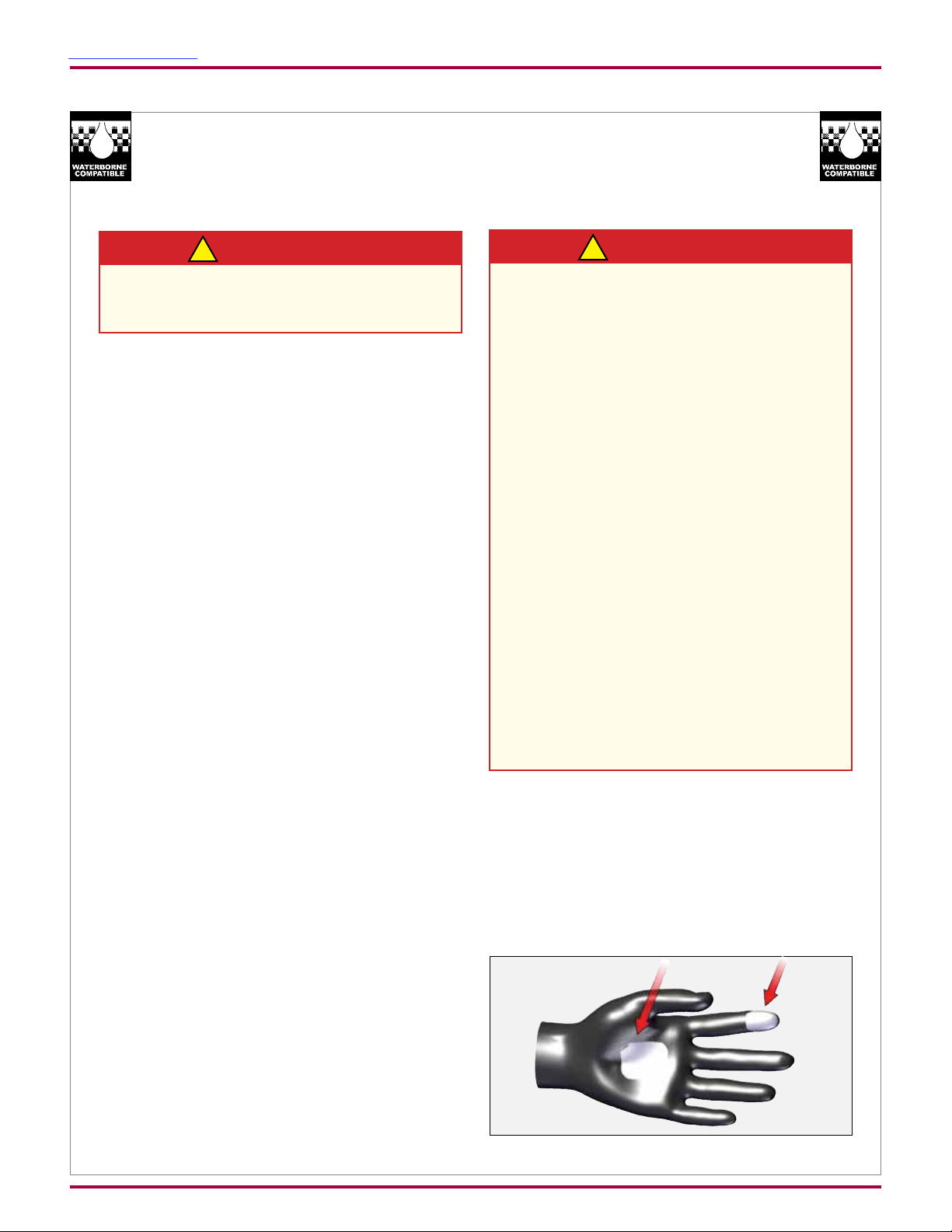
When using an electrostatic handgun, operators
must assure contact with the handle of the applicator
via conductive gloves or gloves with the palm section
cut out.
NOTE: REFER TO NFPA-33 OR SPECIFIC
COUNTRY SAFETY CODES REGARDING
PROPER OPERATOR GROUNDING.
All electrically conductive objects in the spray area,
with the exception of those objects required by the
process to be at high voltage, must be grounded.
Grounded conductive ooring must be provided in
the spray area.
Always turn off the power supply prior to ushing,
cleaning, or working on spray system equipment.
Unless specically approved for use in hazardous
locations, all electrical equipment must be located
outside Class I or II, Division 1 or 2 hazardous
areas, in accordance with NFPA-33.
Avoid installing an applicator into a uid system
where the solvent supply is ungrounded.
Do not touch the applicator electrode while it is
energized.
AH-17-04-R0.0 (11/2017) 6 / 59 www.carlisleft.com

Return To Contents
SAFETY
AREA
Tells where hazards
may occur.
Electrical
Equipment
HAZARD
Tells what the hazard is.
Electrical Discharge
High voltage equipment is
utilized in the process. Arcing
in the vicinity of ammable or
combustible materials may
occur. Personnel are exposed
to high voltage during operation
and maintenance.
Protection against inadvertent
arcing that may cause a re or
explosion is lost if safety circuits
are disabled during operation.
Frequent power supply shutdown indicates a problem in
the system which requires
correction.
An electrical arc can ignite
coating materials and cause a
re or explosion.
SAFEGUARDS
Tells how to avoid the hazard.
Unless specically approved for use in hazardous
locations, the power supply, control cabinet, and all
other electrical equipment must be located outside
Class I or II, Division 1 and 2 hazardous areas in
accordance with NFPA-33 and EN 50176.
Turn the power supply OFF before working on the
equipment.
Test only in areas free of ammable or combustible
material.
Testing may require high voltage to be on, but only
as instructed.
Production should never be done with the safety
circuits disabled.
Before turning the high voltage on, make sure no
objects are within the sparking distance.
Spray Area
Chemical HazardToxic Substances
Certain materials may be
harmful if inhaled, or if there is
contact with the skin.
Explosion Hazard —
Incompatible Materials
Halogenated hydrocarbon
solvents for example:
methylene chloride and
1,1,1,-Trichloroethane are not
chemically compatible with the
aluminum that might be used
in many system components.
The chemical reaction
caused by these solvents
reacting with aluminum can
become violent and lead to an
equipment explosion.
Follow the requirements of the Safety Data Sheet
supplied by coating material manufacturer.
Adequate exhaust must be provided to keep the air
free of accumulations of toxic materials.
Use a mask or respirator whenever there is a chance
of inhaling sprayed materials. The mask must be
compatible with the material being sprayed and its
concentration. Equipment must be as prescribed
by an industrial hygienist or safety expert, and be
NIOSH approved.
Spray applicators require that aluminum inlet ttings
be replaced with stainless steel.
Aluminum is widely used in other spray application
equipment - such as material pumps, regulators,
triggering valves, etc. Halogenated hydrocarbon
solvents must never be used with aluminum
equipment during spraying, ushing, or cleaning.
Read the label or data sheet for the material you
intend to spray. If in doubt as to whether or not a
coating or cleaning material is compatible, contact
your coating supplier. Any other type of solvent may
be used with aluminum equipment.
AH-17-04-R0.0 (11/2017) 7 / 59 www.carlisleft.com

Return To Contents
ATEX
EUROPEAN ATEX DIRECTIVE 2014/34/EU
The following instructions apply to equipment covered
by certicate number Sira 14ATEX 5343:
1. The equipment may be used with ammable
gases and vapors with apparatus groups II and
with temperature class T6.
2. The equipment is only certied for use in ambient
temperatures in the range +5°C to +40°C and
should not be used outside this range.
3. Installation shall be carried out by suitably trained
personnel in accordance with the applicable code
of practice e.g. EN 60079-14:1997.
4. Inspection and maintenance of this equipment
shall be carried out by suitably trained personnel
in accordance with the applicable code of practice
e.g. EN 60079-17.
5. Repair of this equipment shall be carried out by
suitable trained personnel in accordance with the
applicable code of practice e.g. EN 60079-19.
6. Putting into service, use, assembling, and
adjustment of the equipment shall be tted by
suitably trained personnel in accordance with the
manufacturer's documentation.
Refer to the "Table of Contents" of this service manual:
a. Installation
b. Operation
c. Maintenance
d. Parts Identication
7. Components to be incorporated into or used
as replacement parts of the equipment shall be
tted by suitably trained personnel in accordance
with the manufacturer's documentation.
8. The certication of this equipment relies upon the
following materials used in its construction:
If the equipment is likely to come into contact with
aggressive substances, then it is the responsibility
of the user to take suitable precautions that prevent
it from being adversely affected, thus ensuring that
the type of protection provided by the equipment
is not compromised.
Aggressive substances: e.g. acidic liquids or
gases that may attack metals, or solvents that
may affect polymeric materials.
Suitable precautions: e.g. regular checks as part
of routine inspections or establishing from the
material's data sheets that it is resistant to specic
chemicals.
Refer to "Specications" in the "Introduction" section:
a. All uid passages contain stainless steel or
nylon ttings.
b. High voltage cascade is encapsulated with
a solvent resistant epoxy.
9. A recapitulation of the certication marking is
detailed in the "ATEX" section, on the next page,
drawing number: 80777-11 and 80777-12.
10. The characteristics of the equipment shall be
detailed e.g. electrical, pressure, and voltage
parameters.
The manufacturer should note that, on
being put into service, the equipment must
be accompanied by a translation of the
instructions in the language or languages of
the country in which the equipment is to be
used and by the instructions in the original
language.
AH-17-04-R0.0 (11/2017) 8 / 59 www.carlisleft.com

Return To Contents
ATEX REQUIREMENTS
ATEX Requirements
This product provides a direct charge to water based
materials that will improve the transfer efciency
over non-electrostatic products. Because it is direct
charge, the uid delivery system must be isolated
from ground to allow proper electrostatic charging of
the uid.
ATEX
FM REQUIREMENTS
Requirements
These applicators are FM approved when the
product setup is congured to drawings shown on
the following pages. This product is approved for use
only with non-ammable water-based materials when
the materials meet the FM denition for a waterbased
spray material*. It is the end users’ responsibility
to insure the material that is sprayed meets this
requirement.
* FM 7260 waterbased spray material - a material that
does not sustain burning when tested in accordance
with ASTM D 4206.
®
By Ransburg
80777-11
80777-12
AH-17-04-R0.0 (11/2017) 9 / 59 www.carlisleft.com
Return To Contents
ATEX
RANSFLEX RFXw - WATER BASE ONLY
81520 -
Base
Model No.
(Ordering Information Only)
B
ABC0EF
Optional
Designations
A
C
E
F
CONFIGURATION DWG. 81521-00
AH-17-04-R0.0 (11/2017) 10 / 59 www.carlisleft.com
REV. A

Return To Contents
ATEX
“S” (Fluid Nozzle) “T” (Pressure Reducer)“R” (Air Cap)
ATOMIZATION - TABLE OF “A” DASHES
“A” Dash No.
“A” Description
“R”
“S”
0 V SERIES 1.2mm 80265-00 80264-12 79809-00
1 V SERIES 1.4mm 80265-00 80264-14 79809-00
2 V SERIES 1.8mm 80265-00 80264-18 79809-00
3 C SERIES 1.2mm 80231-00 80230-12 79809-03
4 C SERIES 1.4mm 80231-00 80230-14 79809-03
5 C SERIES 1.8mm 80231-00 80230-18 79809-03
6 T SERIES 1.2mm 80240-00 80239-12 74963-05
7 T SERIES 1.4mm 80240-00 80239-14 74963-05
8 T SERIES 1.8mm 80240-00 80239-18 74963-05
9 ROUND SPRAY 79962-00 80400-00 74963-05
80775-01 “U” 80775-00 “U”
FLUID CONTROL - TABLE OF “B” DASHES
“B” Dash No.
“B” Description
“T”
“U”
1 ADJUSTABLE FLUID 80775-00
2 NON-ADJUSTABLE FLUID 80775-01
“V”
TRIGGER - TABLE OF “C” DASHES
“C” Dash No.
“C” Description
1 2 FINGER TRIGGER 80211-00
2 4 FINGER TRIGGER 80386-00
3 2 FINGER SMALL PROFILE 80566-00
AH-17-04-R0.0 (11/2017) 11 / 59 www.carlisleft.com
“V”
Return To Contents
ATEX
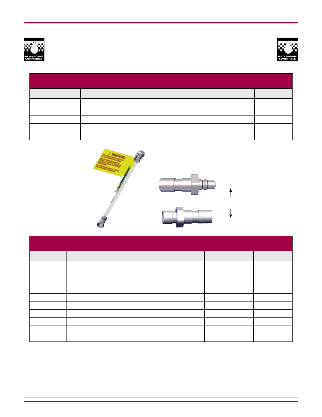
FLUID HOSE - TABLE OF “E” DASHES
“E” Dash No.
0 NO FLUID HOSE ---
1 3/16 ID, 10m 80500-10
2 3/16 ID, 15m 80500-15
3 1/4 ID, 10m 80501-10
4 1/4 ID, 15m 80501-15
“E” Description
80869-00
“Z”
80558-XX “Y”
AIR HOSE - TABLE OF “F” DASHES
80868-00
“X”
“F” Dash No.
0 NO AIR HOSE, STANDARD --- 80868-00
1 STANDARD AIR HOSE, 5m 80558-05 80868-00
2 STANDARD AIR HOSE, 10m 80558-10 80868-00
3 STANDARD AIR HOSE, 15m 80558-15 80868-00
4 STANDARD AIR HOSE, 20m 80558-20 80868-00
5 NO AIR HOSE, QD --- 80869-00
6 QD AIR HOSE, 10m 80558-06 80869-00
7 QD AIR HOSE, 10m 80558-11 80869-00
8 QD AIR HOSE, 15m 80558-16 80869-00
9 QD AIR HOSE, 20m 80558-21 80869-00
AH-17-04-R0.0 (11/2017) 12 / 59 www.carlisleft.com
“F” Description
“Z”“Y”

Return To Contents
ATEX
AVAILABLE ACCESSORIES
Part #
80264-07 V SERIES 0.7mm 80265-00 Black
80264-10 V SERIES 1.0mm 80265-00 Black
80239-07 T SERIES 0.7mm 80240-00 Black
80239-10 T SERIES 1.0mm 80240-00 Black
Description
For Use With
Nozzle Color
AH-17-04-R0.0 (11/2017) 13 / 59 www.carlisleft.com

Return To Contents
INTRODUCTION
INTRODUCTION
GENERAL DESCRIPTION
The Ransex is an air atomizing applicator powered
only by a pressurized air source. Pressurized air creates
rotation of a turbine generator that powers a cascade.
The cascade generates a high voltage DC charge to
the electrode creating an electrostatic eld between
the atomizer and the target.
One of the many features of the Ransex applicator
system is that the electrical energy, which is available
from the resistive charging electrode, is limited to the
optimum level of safety and efciency. The system is
incapable of releasing sufcient electrical or thermal
energy during normal operating conditions to cause
ignition of specic hazardous materials in their most
easily ignited concentrations in air.
As the applicator electrode approaches ground,
applicator circuitry causes the high voltage to approach
zero while the current approaches its maximum value.
This performance is validated by independent test
agencies that give ATEX EN 50050 approvals or FM
7260 approvals.
RANSFLEX NEW FEATURES
• Light weight and easy to maneuver.
• Ergonomic handle design to reduce
operator fatigue.
• Three phases of turbine protection:
- Divorced turbine air supply cartridge
- Sealed nozzle/Atomization passages
- Strategic turbine location
• DeVilbiss spray technology integration
into atomization.
• Simultaneous fan/atom pressure adjustment with
compensation valve.
This Ransex model is designed specically for direct
charge waterbase applications only. The waterborne
uid supply system must be isolated from ground to
allow proper electrostatic charging of the uid.
The water base materials must be classied as nonamable spray material. This means the mixture with air
cannot be ignited by an energy source less than 500 mJ.
AH-17-04-R0.0 (11/2017) 14 / 59 www.carlisleft.com

Return To Contents
INTRODUCTION
SPECIFICATIONS:
81520 RANSFLEX DIRECT CHARGE WATERBASE
Environmental/Physical
Applicator Length: 273mm (10.75 inches)
Weight: (Without Hose) 620 grams (22 oz.)
Hose 80558-XX Lengths (Std): 5m, 10m, 15m and 20m
Electrical
Operating Voltage: 65kV DC (-) maximum
Current Output: 120 microamperes maximum
Paint Resistance:* Water base paint only
Part Sprayability: Determine sprayability of part to be coated using 76652, Test Equipment
(See current “Paint, HV & SCI Test Equipment” service manual TE-98-01)
* Use Model No. 76652, Test Equipment
Mechanical
Fluid Flow Capacity: 1000 ml/minute**
Wetted Parts: Stainless, polyethylene, nylon, acetal polymer
Operating Pressure (Air Spray)
Fluid: (0-6.9 bar) 0-100 psi
Air: (0-6.9 bar) 0-100 psi
Ambient Temp.: 40°C to 5°C (104°F to 32°F)
Consumption (With Voltage): 438 SLPM (15.4 SCFM) @ 2.8 bar (40 psig) @ Handle Inlet
Sound Level: 92dB (A) @ 2.8 bar (40 psig) Inlet, 1m from applicator
** This reects the maximum uid volume the applicator can deliver. The maximum spray volume that can be effectively
atomized depends on uid rheology, spray technology, and nish quality required.
AH-17-04-R0.0 (11/2017) 15 / 59 www.carlisleft.com
Return To Contents
INTRODUCTION
11
9
3
4
2
1
10
5
12
7
6
8
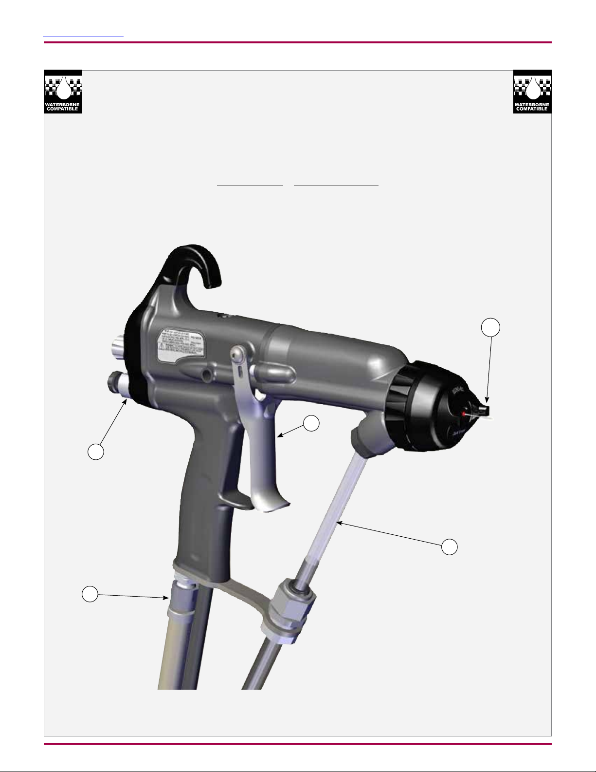
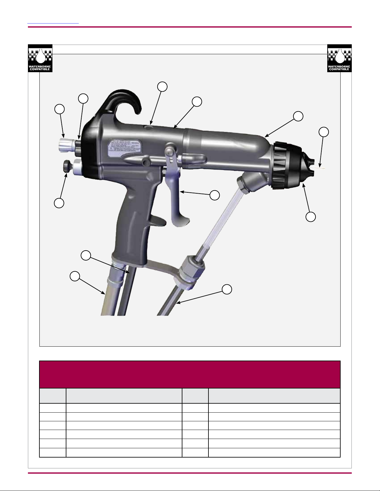
Figure 1: RansFlex Water Base Direct Charge Electrostatic Spray Applicator 81520
RANSFLEX WATER BASE DIRECT CHARGE ELECTROSTATIC
SPRAY APPLICATOR 81520
No.
1 Needle/Electrode
2 Barrel
3 Handle
4 Fan Adjustment
5 Fluid Adjustment
6 Air Hose
Description
No.
7 Exhaust Air Hose
8 Waterborne Fluid Hose
9 Voltage On/Off Switch
10 Trigger
11 Compensation Valve
12
Description
Air Cap / Fluid Nozzle
AH-17-04-R0.0 (11/2017) 16 / 59 www.carlisleft.com

Return To Contents
INTRODUCTION
8
1
9
3 2
10
5
3
7
11
2
6
4
Figure 2: RansFlex Typical Waterborne Installation
RANSFLEX WATERBORNE TYPICAL INSTALLATION
No.
1 RansFlex 81520
2 Ball Valve
3 Air Regulator with Pressure Gauge
4 Air / Water Separator
5 Main Air Supply Line
6 Fluid Supply (Grounded)
Description
No.
7 Fluid Regulator
8 Air Hose (80558-XX)
9 Air Hose Ground Wire
10 Isolated Waterborne Hose
11 Voltage Isolation / Protection
Description
AH-17-04-R0.0 (11/2017) 17 / 59 www.carlisleft.com
Return To Contents
Air Hose
INSTALLATION
INSTALLATION
W A R N I N G
!
For proper safe function of the applicator and
operator the 80558-XX Air Hose Assembly must be
used
(either standard or quick disconnect style).
Filters
1. Install an air lter assembly on the outlet of the
main air regulator. The lter should be 5 micron
with a maximum working pressure of at least 100
psig (6.9 bar). For Class 3 air quality, which is a 5
micron size and has a dew point of -4°F (-20°C),
the relative humidity (RH) of the air should be 5%.
2.
Ransburg recommends that a uid lter be installed
at the output of the uid supply (pressure pot,
pump, circulating system, etc.). It is the end user's
responsibility to install the proper lter that meets
their system's requirements.
81520 RANSFLEX DIRECT
CHARGE INSTALLATION
W A R N I N G
!
The user MUST read and be familiar with the
"Safety" section of this manual.
This hand held device is intended to be used
by trained personnel ONLY.
This manual MUST be read and thoroughly
understood by ALL personnel who operate,
clean, or maintain this equipment! Special care
should be taken to ensure that the warnings and
requirements for operating and servicing safely
are followed. The user should be aware of and
adhere to ALL local building and re codes and
ordinances as well as NFPA, OSHA, and all
related country safety codes prior to installing,
operating, and/or servicing this equipment.
Personnel MUST be GROUNDED to prevent
a shock or spark during electrostatic operation.
Install and route the hoses so they are NOT
exposed to temperatures in excess of 120° F
(49° C) and so that all hose bends are NO LESS
than a 6-inch (15cm) radius. Failure to comply
with these parameters could cause equipment
malfunction that might create HAZARDOUS
CONDITIONS!
GENERAL INSTALLATION
REQUIREMENTS
1. Operator must make skin contact with handle of
applicator. If gloves are required use either gloves
with palm and nger cut out or conductive gloves.
See accessory pages for conductive gloves.
AH-17-04-R0.0 (11/2017) 18 / 59 www.carlisleft.com
 Loading...