

Ransburg MICROPAK A11789 Service Manual

MICROPMICROP
MICROP
MICROPMICROP
AKAK
AK
AKAK
TM TM
TM
TM TM
CONTROLLERCONTROLLER
CONTROLLER
CONTROLLERCONTROLLER
SERVICE MANUAL
CP-06-01CP-06-01
CP-06-01
CP-06-01CP-06-01
January - 2007
MODEL: A1MODEL: A1
MODEL: A1
MODEL: A1MODEL: A1
I/O
17891789
1789
17891789
IMPORIMPOR
IMPOR
IMPORIMPOR
carefully read SAFETY PRECAUTIONS,carefully read SAFETY PRECAUTIONS,
carefully read SAFETY PRECAUTIONS,
carefully read SAFETY PRECAUTIONS,carefully read SAFETY PRECAUTIONS,
starting on page 1, and all instructions in thisstarting on page 1, and all instructions in this
starting on page 1, and all instructions in this
starting on page 1, and all instructions in thisstarting on page 1, and all instructions in this
manual. Keep this Service Manual for futuremanual. Keep this Service Manual for future
manual. Keep this Service Manual for future
manual. Keep this Service Manual for futuremanual. Keep this Service Manual for future
reference.reference.
reference.
reference.reference.
TT
ANTANT
T
ANT
TT
ANTANT
: Before using this equipment,: Before using this equipment,
: Before using this equipment,
: Before using this equipment,: Before using this equipment,
Service Manual Price: $30.00 (U.S.)Service Manual Price: $30.00 (U.S.)
Service Manual Price: $30.00 (U.S.)
Service Manual Price: $30.00 (U.S.)Service Manual Price: $30.00 (U.S.)

CP-06-01

CONTENTSCONTENTS
CONTENTS
CONTENTSCONTENTS
SAFETY:SAFETY:
SAFETY:
SAFETY:SAFETY:
MicroPak Controller - Contents
PAGEPAGE
PAGE
PAGEPAGE
1-41-4
1-4
1-41-4
SAFETY PRECAUTIONS............................................................................................................
HAZARDS/SAFEGUARDS.........................................................................................................
INTRODUCTION:INTRODUCTION:
INTRODUCTION:
INTRODUCTION:INTRODUCTION:
GENERAL DESCRIPTION..........................................................................................................
SAFETY FEATURES...................................................................................................................
DISPLAYS....................................................................................................................................
CURRENT CONTROL................................................................................................................
SPECIFICATIONS.......................................................................................................................
INSTALLATION:INSTALLATION:
INSTALLATION:
INSTALLATION:INSTALLATION:
MICROPAK INPUT POWER.......................................................................................................
SAFETY GROUND......................................................................................................................
LOW VOLTAGE CABLE..............................................................................................................
INTERLOCKS AND I/O...............................................................................................................
DESCRIPTION OF TABLE 1 INTERLOCK &
I/O TERMINALS...........................................................................................................................
CURRENT CONTROL................................................................................................................
DIP SWITCH SUMMARY............................................................................................................
MICROPAK GROUND THEORY................................................................................................
OPERATION:OPERATION:
OPERATION:
OPERATION:OPERATION:
OPERATING CONTROLS..........................................................................................................
OPERATING PROCEDURES....................................................................................................
1
2-4
5-65-6
5-6
5-65-6
5
5
5
5
6
7-157-15
7-15
7-157-15
7
8
8
9
11
11-13
13-14
15
16-1816-18
16-18
16-1816-18
16-17
17-18
MAINTENANCE:MAINTENANCE:
MAINTENANCE:
MAINTENANCE:MAINTENANCE:
TROUBLESHOOTING................................................................................................................
CABLE CONTINUITY TEST........................................................................................................
TROUBLESHOOTING GUIDE...................................................................................................
TABLE 2 OHMMETER MEASUREMENTS................................................................................
PARTS IDENTIFICATION:PARTS IDENTIFICATION:
PARTS IDENTIFICATION:
PARTS IDENTIFICATION:PARTS IDENTIFICATION:
MICROPAK CONTROLLER PARTS DIAGRAM / PARTS LIST...............................................
A11789-01 STAND-ALONE CONTROL / POWER SUPPLY
ASSEMBLY/PARTS LIST............................................................................................................
MICROPAK STAND-ALONE CONTROL / POWER SUPPLY
MODEL IDENTIFICATION..........................................................................................................
A11789-01 STAND-ALONE CONTROL / POWER SUPPLY SCHEMATIC.............................
WARRANTY POLICIES:WARRANTY POLICIES:
WARRANTY POLICIES:
WARRANTY POLICIES:WARRANTY POLICIES:
LIMITED WARRANTY.................................................................................................................
CP-06-01
19-2219-22
19-22
19-2219-22
19
19
20-21
22
23-2923-29
23-29
23-2923-29
23-24
25-28
28
29
3131
31
3131
31

MicroPak Controller - Safety
SAFETYSAFETY
SAFETY
SAFETYSAFETY
SAFETY PRECAUTIONSSAFETY PRECAUTIONS
SAFETY PRECAUTIONS
SAFETY PRECAUTIONSSAFETY PRECAUTIONS
W A R N I N GW A R N I N G
W A R N I N G
W A R N I N GW A R N I N G
!!
!
!!
Before operating, maintaining or servicing any
ITW Ransburg electrostatic coating system, read
and understand all of the technical and safety
literature for your ITW Ransburg products. This
manual contains information that is important for
you to know and understand. This information
relates to USER SAFETY and PREVENTING
EQUIPMENT PROBLEMS. To help you recognize
this information, we use the following symbols.
Please pay particular attention to these sections.
A WARNING!A WARNING!
A WARNING!
A WARNING!A WARNING!
to a situation that might cause serious injuryto a situation that might cause serious injury
to a situation that might cause serious injury
to a situation that might cause serious injuryto a situation that might cause serious injury
if instructions are not followed.if instructions are not followed.
if instructions are not followed.
if instructions are not followed.if instructions are not followed.
A CAUTION!A CAUTION!
A CAUTION!
A CAUTION!A CAUTION!
how to prevent damage to equipment or howhow to prevent damage to equipment or how
how to prevent damage to equipment or how
how to prevent damage to equipment or howhow to prevent damage to equipment or how
to avoid a situation that might cause minorto avoid a situation that might cause minor
to avoid a situation that might cause minor
to avoid a situation that might cause minorto avoid a situation that might cause minor
injury.injury.
injury.
injury.injury.
A NOTE is information relevant to theA NOTE is information relevant to the
A NOTE is information relevant to the
A NOTE is information relevant to theA NOTE is information relevant to the
procedure in progress.procedure in progress.
procedure in progress.
procedure in progress.procedure in progress.
While this manual lists standard specifications
and service procedures, some minor deviations
may be found between this literature and your
equipment. Differences in local codes and plant
requirements, material delivery requirements, etc.,
make such variations inevitable. Compare this
manual with your system installation drawings
and appropriate ITW Ransburg equipment manuals
to reconcile such differences.
states information to alert youstates information to alert you
states information to alert you
states information to alert youstates information to alert you
states information that tellsstates information that tells
states information that tells
states information that tellsstates information that tells
> The user
the Safety Section in this manual and the
ITW Ransburg safety literature therein identified.
> This manual
understood by
clean or maintain this equipment! Special
care should be taken to ensure that the
WARNINGSWARNINGS
WARNINGS and safety requirements for
WARNINGSWARNINGS
operating and servicing the equipment are
followed. The user should be aware of and
adhere to
and ordinances as well as
SAFETY STANDARD, SAFETY STANDARD,
SAFETY STANDARD, prior to installing,
SAFETY STANDARD, SAFETY STANDARD,
MUSTMUST
MUST read and be familiar with
MUSTMUST
MUSTMUST
MUST be read and thoroughly
MUSTMUST
ALLALL
ALL personnel who operate,
ALLALL
ALLALL
ALL local building and fire codes
ALLALL
NFPA-33NFPA-33
NFPA-33
NFPA-33NFPA-33
W A R N I N GW A R N I N G
W A R N I N G
W A R N I N GW A R N I N G
!!
!
!!
> The hazards shown on the following page
may occur during the normal use of this
equipment. Please read the hazard chart
beginning on page 2.
Careful study and continued use of this manual will
provide a better understanding of the equipment
and process, resulting in more efficient operation,
longer trouble-free service and faster, easier
troubleshooting. If you do not have the manuals
and safety literature for your ITW Ransburg system,
contact your local Ransburg representative or
ITW Ransburg.
11
1
11
CP-06-01
MicroPak Controller - Safety
AREAAREA
AREA
AREAAREA
Tells where hazards
may occur.
Spray AreaSpray Area
Spray Area
Spray AreaSpray Area
HAZARDHAZARD
HAZARD
HAZARDHAZARD
Tells what the hazard is.
Fire Hazard
Improper or inadequate opera-tion
and maintenance procedures will
cause a fire hazard.
Protection against inadvertent
arcing that is capable of causing
fire or explosion is lost if any safety
interlocks are disabled during
operation. Frequent power supply
shutdown indicates a problem in
the system requiring correction.
SAFEGUARDSSAFEGUARDS
SAFEGUARDS
SAFEGUARDSSAFEGUARDS
Tells how to avoid the hazard.
Fire extinguishing equipment must be present in the
spray area and tested periodically.
Spray areas must be kept clean to prevent the
accumulation of combustible residues.
Smoking must never be allowed in the spray area.
The high voltage supplied to the atomizer must be
turned off prior to cleaning, flushing or maintenance.
When using solvents for cleaning:
Those used for equipment flushing should have flash
points equal to or higher than those of the coating
material.
Those used for general cleaning must have flash
points above 100oF (37.8oC).
Spray booth ventilation must be kept at the rates
required by NFPA-33, OSHA, and local codes. In
addition, ventilation must be maintained during
cleaning operations using flammable or combustible
solvents.
Electrostatic arcing must be prevented.
Test only in areas free of combustible material.
Testing may require high voltage to be on, but only as
instructed.
Non-factory replacement parts or unauthorized
equipment modifications may cause fire or injury.
If used, the key switch bypass is intended for use only
during set-up operations. Production should never be
done with safety interlocks disabled.
Never use equipment intended for use in waterborne
installations to spray solvent based materials.
The paint process and equipment should be set up
and operated in accordance with NFPA- 33, NED, and
OSHA requirements.
CP-06-01
22
2
22

MicroPak Controller - Safety
AREAAREA
AREA
AREAAREA
Tells where hazards
may occur.
General Use andGeneral Use and
General Use and
General Use andGeneral Use and
MaintenanceMaintenance
Maintenance
MaintenanceMaintenance
ElectricalElectrical
Electrical
ElectricalElectrical
EquipmentEquipment
Equipment
EquipmentEquipment
HAZARDHAZARD
HAZARD
HAZARDHAZARD
Tells what the hazard is.
Improper operation or maintenance
may create a hazard.
Personnel must be properly trained
in the use of this equipment.
High voltage equipment is utilized.
Arcing in areas of flammable or
combustible materials may occur.
Personnel are exposed to high
voltage during operation and
maintenance.
Protection against inadvertent
arcing that may cause a fire or
explosion is lost if safety circuits
are disabled during operation.
Frequent power supply shut-down
indicates a problem in the system
which requires correction.
An electrical arc can ignite coating
materials and cause a fire or
explosion.
SAFEGUARDSSAFEGUARDS
SAFEGUARDS
SAFEGUARDSSAFEGUARDS
Tells how to avoid the hazard.
Personnel must be given training in accordance with
the requirements of NFPA-33.
Instructions and safety precautions must be read and
understood prior to using this equipment.
Comply with appropriate local, state, and national
codes governing ventilation, fire protection, operation
maintenance, and housekeeping. Reference OSHA,
NFPA-33, and your insurance company requirements.
The power supply, optional remote control cabinet,
and all other electrical equipment must be located
outside Class I or II, Division 1 and 2 hazardous
areas. Refer to NFPA-33.
Turn the power supply OFF before working on the
equipment.
Test only in areas free of flammable or combustible
material.
Testing may require high voltage to be on, but only as
instructed.
Production should never be done with the safety
circuits disabled.
Before turning the high voltage on, make sure no
objects are within the sparking distance.
ExplosionExplosion
Explosion
ExplosionExplosion
Hazard /Hazard /
Hazard /
Hazard /Hazard /
IncompatibleIncompatible
Incompatible
IncompatibleIncompatible
MaterialsMaterials
Materials
MaterialsMaterials
33
3
33
Halogenated hydrocarbon solvents
for example: methylene chloride
and 1,1,1,-Trichloroethane are not
chemically compatible with the
aluminum that might be used in
many system components. The
chemical reaction caused by these
solvents reacting with aluminum
can become violent and lead to an
equipment explosion.
Aluminum is widely used in other spray application
equipment - such as material pumps, regulators,
triggering valves, etc. Halogenated hydrocarbon
solvents must never be used with aluminum equipment
during spraying, flushing, or cleaning. Read the label
or data sheet for the material you intend to spray. If
in doubt as to whether or not a coating or cleaning
material is compatible, contact your material supplier.
Any other type of solvent may be used with aluminum
equipment.
CP-06-01

MicroPak Controller - Safety
AREAAREA
AREA
AREAAREA
Tells where hazards
may occur.
Spray Area /Spray Area /
Spray Area /
Spray Area /Spray Area /
High VoltageHigh Voltage
High Voltage
High VoltageHigh Voltage
EquipmentEquipment
Equipment
EquipmentEquipment
HAZARDHAZARD
HAZARD
HAZARDHAZARD
Tells what the hazard is.
This is a high voltage device that
can produce electrical arcs capable
of igniting coating materials.
SAFEGUARDSSAFEGUARDS
SAFEGUARDS
SAFEGUARDSSAFEGUARDS
Tells how to avoid the hazard.
Parts being sprayed must be supported on conveyors
or hangers and be grounded. The resistance between
the part and ground must not exceed 1 megohm.
(Reference NFPA- 33.)
A safe distance must be maintained between the
parts being coated and the atomizer bell. A distance
of at least 1 inch for each 10 KV of power supply
output voltage is required at all times.
Parts must be supported so that they will not swing
and reduce the clearance specified above.
All electrically conductive objects in the spray area,
with the exception of those objects required by the
process to be at high voltage, must be grounded.
Unless specifically approved for use in hazardous
locations, the power supply and other electrical
equipment must not be used in Class I, Division 1 or
2 locations.
CP-06-01
44
4
44

MicroPak Controller - Introduction
INTRODUCTIONINTRODUCTION
INTRODUCTION
INTRODUCTIONINTRODUCTION
GENERAL DESCRIPTIONGENERAL DESCRIPTION
GENERAL DESCRIPTION
GENERAL DESCRIPTIONGENERAL DESCRIPTION
TMTM
TM
MicroPakMicroPak
The
MicroPak
MicroPakMicroPak
voltage to the cascade inside the Spray Gun
Assembly.
The MicroPak Controller together with the Spray
Gun Assembly and it’s Low Voltage Cable is a
System. It is unique in that it contains a built-in DC
Power Supply and is capable of operating either 1
or 2 MicroPak control units.
The MicroPak uses a combination of proven high
voltage generation technology including
microprocessor-based control with diagnostic and
communication functions. The processor circuitry
provides the maximum in applicator transfer
efficiency.
SAFETYSAFETY
SAFETY
SAFETYSAFETY
TMTM
Controller Controller
Controller
Controller Controller
FEA FEA
FEA
FEA FEA
, is used to provide
TURESTURES
TURES
TURESTURES
CURRENT CONTROLCURRENT CONTROL
CURRENT CONTROL
CURRENT CONTROLCURRENT CONTROL
The current setpoint limits the maximum current
that the cascade can produce. The voltage
setpoint sets the maximum voltage the cascade
can produce. The MicroPak will first attempt to
achieve current output setpoint. If the voltage
setpoint is set low, then the voltage setpoint will not
allow the current setpoint to be achieved.
VV
oltage Controloltage Control
V
oltage Control
VV
oltage Controloltage Control
The Over-Current setpoint can be monitored on
the μa Display by pressing the SET push-button
and holding for one second. It does provide a hard
shut-down if the output current exceeds the
setpoint. The kV setpoint is also displayed on the
kV display when the SET push-button is pressed
for one second.
DISPLADISPLA
DISPLA
DISPLADISPLA
The front panel displays for output voltage and
current indicate the true outputs from the cascade
or the tip voltage for indirect charge, and waterborne
applications. They are derived from feedback
signals in the low voltage cable between the
controller and the cascade.
YSYS
YS
YSYS
55
5
55
CP-06-01

SPECIFICASPECIFICA
SPECIFICA
SPECIFICASPECIFICA
(A(A
t Sea-Level Conditions)t Sea-Level Conditions)
(A
t Sea-Level Conditions)
(A(A
t Sea-Level Conditions)t Sea-Level Conditions)
Environmental / PhysicalEnvironmental / Physical
Environmental / Physical
Environmental / PhysicalEnvironmental / Physical
Temp. Operating:Temp. Operating:
Temp. Operating: (0
Temp. Operating:Temp. Operating:
TIONSTIONS
TIONS
TIONSTIONS
o
to 55o C)
MicroPak Controller - Introduction
NOTESNOTES
NOTES
NOTESNOTES
Storage:Storage:
Storage: (-40
Storage:Storage:
Humidity:Humidity:
Humidity: (95% Non-Condensing)
Humidity:Humidity:
Cabinet Size:Cabinet Size:
Cabinet Size: 13” Wide
Cabinet Size:Cabinet Size:
Weight:Weight:
Weight: 19 lbs.
Weight:Weight:
ElectricalElectrical
Electrical
ElectricalElectrical
DC Power Required: *DC Power Required: *
DC Power Required: *
DC Power Required: *DC Power Required: *
(per MicroPak)(per MicroPak)
(per MicroPak) 24VDC at 2.5A
(per MicroPak)(per MicroPak)
AC Electrical Requirements:AC Electrical Requirements:
AC Electrical Requirements:
AC Electrical Requirements:AC Electrical Requirements:
90-264 VAC @ 1.5 amps @
47/63 Hertz
**
DC power supplied from 24VDC built-in,DC power supplied from 24VDC built-in,
*
DC power supplied from 24VDC built-in,
**
DC power supplied from 24VDC built-in,DC power supplied from 24VDC built-in,
regulated power supy which has over-currentregulated power supy which has over-current
regulated power supy which has over-current
regulated power supy which has over-currentregulated power supy which has over-current
(40%) and over-voltage (20%) protection.(40%) and over-voltage (20%) protection.
(40%) and over-voltage (20%) protection.
(40%) and over-voltage (20%) protection.(40%) and over-voltage (20%) protection.
o
C to 85o C)
19” Deep
7” Height
(fully loaded output),
HP404 Cascade
Controls: Controls:
Controls:
Controls: Controls:
Discrete signals available via I/O Module
(Part #76037-03)
Analog In: Analog In:
Analog In: KV SET (0-10VDC)
Analog In: Analog In:
OVER-CURRENT SET
(0-10VDC)
Discrete Out: Discrete Out:
Discrete Out: HV ON (+24V)
Discrete Out: Discrete Out:
HV READY (+24V)
OVER-CURRENT FAULT
(+24V)
Discrete In: Discrete In:
Discrete In: HV RESET (+24V)
Discrete In: Discrete In:
HV ON (+24V)
CP-06-01
66
6
66
MicroPak Controller - Installation
INSTINST
INST
INSTINST
MICROPAK INPUTMICROPAK INPUT
MICROPAK INPUT
MICROPAK INPUTMICROPAK INPUT
POWERPOWER
POWER
POWERPOWER
For non-conduit installations, plug the detachable
AC line cord into the receptacle on the rear of the
MicroPak Controller. Plug the other end of the line
cord into a properly grounded 120 VAC outlet.
ALLAALLA
ALLA
ALLAALLA
NOTENOTE
NOTE
NOTENOTE
TIONTION
TION
TIONTION
> In general, conduit must be used for
approved AC installation, however, if national and local codes permit, the AC power
may be supplied via the factory supplied
line cord.
For installations where it is required to run the AC
input wiring in conduit, perform the following:
1. Ensure the AC line cord is unplugged and
remove the top cover from the controller (see
Figure 9).
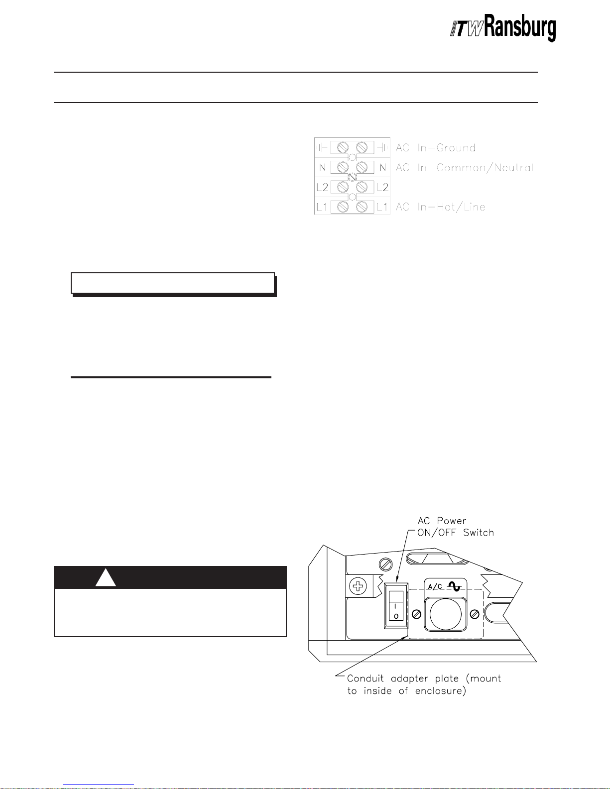
Figure 1: Terminal Block 1 (1TB)Figure 1: Terminal Block 1 (1TB)
Figure 1: Terminal Block 1 (1TB)
Figure 1: Terminal Block 1 (1TB)Figure 1: Terminal Block 1 (1TB)
3. Remove the mounting hardware from the AC
Inlet Receptacle and remove it from the rear of the
control unit.
4. Install the Conduit Adapter Plate (supplied)
(76453) in the hole where the AC Inlet Receptacle
was removed (see Figure 2).
5. Install the AC line cord through the Conduit
Adapter Plate using conduit and wire to 1TB as
follows:
Hot/Line to 1TB-L1
Neutral/common to 1TB-N
Ground to 1TB-Ground
6. Reinstall top cover on controller.
2. Remove the AC Inlet Receptacle wiring from
1TB-L1, 1TB-N, and 1TB-Ground (see Figure 1
for AC input wiring locations).
W A R N I N GW A R N I N G
W A R N I N G
W A R N I N GW A R N I N G
!!
!
!!
> Always double check that the control
unit is unplugged from its AC outlet before
working with any internal wiring.
77
7
77
Figure 2: Installation of Conduit Adapter PlateFigure 2: Installation of Conduit Adapter Plate
Figure 2: Installation of Conduit Adapter Plate
Figure 2: Installation of Conduit Adapter PlateFigure 2: Installation of Conduit Adapter Plate
CP-06-01

MicroPak Controller - Installation
SAFETY GROUNDSAFETY GROUND
SAFETY GROUND
SAFETY GROUNDSAFETY GROUND
Install the ground wire assembly supplied with the
MicroPak Controller from the ground stud on the
rear of the controller to a true earth ground. For
maximum noise immunity, cut the ground wire
assembly to the shortest length required and
reinstall the end lug before making connections.
C A U T I O NC A U T I O N
C A U T I O N
C A U T I O NC A U T I O N
!!
!
!!
> The ground wire assembly
connected from the MicroPak Controller
ground stud to a true earth ground.
LOW VOLLOW VOL
LOW VOL
LOW VOLLOW VOL
Standard Low VStandard Low V
Standard Low V
Standard Low VStandard Low V
(A1(A1
1791-XX)1791-XX)
(A1
1791-XX)
(A1(A1
1791-XX)1791-XX)
Plug the connector of the low voltage cable
assembly into the appropriate receptacle on the
rear of the controller (see Figure 3). P1 is the
output for the leftmost MicroPak control unit, when
viewed from the front, and P2 is the output for the
rightmost MicroPak control unit, if installed. When
making the connection, line the red dot on the
connector with the red mark on the receptacle and
push in until it clicks. To remove, simply pull back
on the knurled portion of the connector. Attach the
low voltage cable(s) to the stress relief bar using
TR-SSEM-200 cable ties (supplied) as shown in
Figure 3.
Junction Box CablesJunction Box Cables
Junction Box Cables
Junction Box CablesJunction Box Cables
(A1(A1
1498-XX and A11498-XX and A1
(A1
1498-XX and A1
(A1(A1
1498-XX and A11498-XX and A1
The spray gun can be ordered with special low
voltage cables (A11498-XX and A11356-XX) for
splicing to a junction box. This is sometimes done
in the field, to reduce the amount of cable that has
to be replaced if a failure of the cable occurs. The
TT
AGE CABLEAGE CABLE
T
AGE CABLE
TT
AGE CABLEAGE CABLE
oltage Cableoltage Cable
oltage Cable
oltage Cableoltage Cable
MUSTMUST
MUST be
MUSTMUST
1356-XX)1356-XX)
1356-XX)
1356-XX)1356-XX)
control unit and gun ends of these cables attach
as described in the standard low voltage cable
section above. Follow the instructions below to
wire the junction box ends of these cables:
Junction Box in Hazardous LocationJunction Box in Hazardous Location
Junction Box in Hazardous Location
Junction Box in Hazardous LocationJunction Box in Hazardous Location
If the junction box is in the hazardous location, an
explosion-proof junction box must be used. In this
case, connect the numbered wires of cable
A11356-XX to the same numbered wire of cable
A11498-XX using a terminal strip inside the
explosion-proof junction box. Ensure the junction
box is grounded to earth ground. Connect wire 18
(braid) of cable A11498-XX to the junction box
(ground). Seal the cable in the explosion-proof
junction box using appropriate explosion-proof
fittings and sealing compound. The exposed area
of the cable braids must be located on the junction
box side of the sealing compound.
Junction Box in Non-HazardousJunction Box in Non-Hazardous
Junction Box in Non-Hazardous
Junction Box in Non-HazardousJunction Box in Non-Hazardous
LocationLocation
Location
LocationLocation
If the junction box is in a non-hazardous location,
then it is not necessary to use an explosion-proof
junction box. In this case, use the supplied cable
gland (A11357-02) and gland nut (A11358-02) to
secure the cables at their entry and exit to the
junction box. Install the cable gland in the junction
box and position the cable so that the spring of the
gland makes contact to the exposed braid of the
cable when the gland nut is tightened. Ensure the
junction box is grounded to earth ground. Connect
the numbered wires of cable A11356-XX to the
same numbered wire of cable A11498-XX using a
terminal strip inside the junction box. The braid of
cable A11498-XX will be grounded through its
contact to the cable gland spring and the grounded
junction box. Wire 18, therefore is unnecessary
and may be trimmed off. Connection in this
manner will ensure maximum noise immunity.
CP-06-01
88
8
88
 Loading...