

SERVICE MANUAL
LN-9258-07.2
(Replaces LN-9258-07.1)
April - 2013
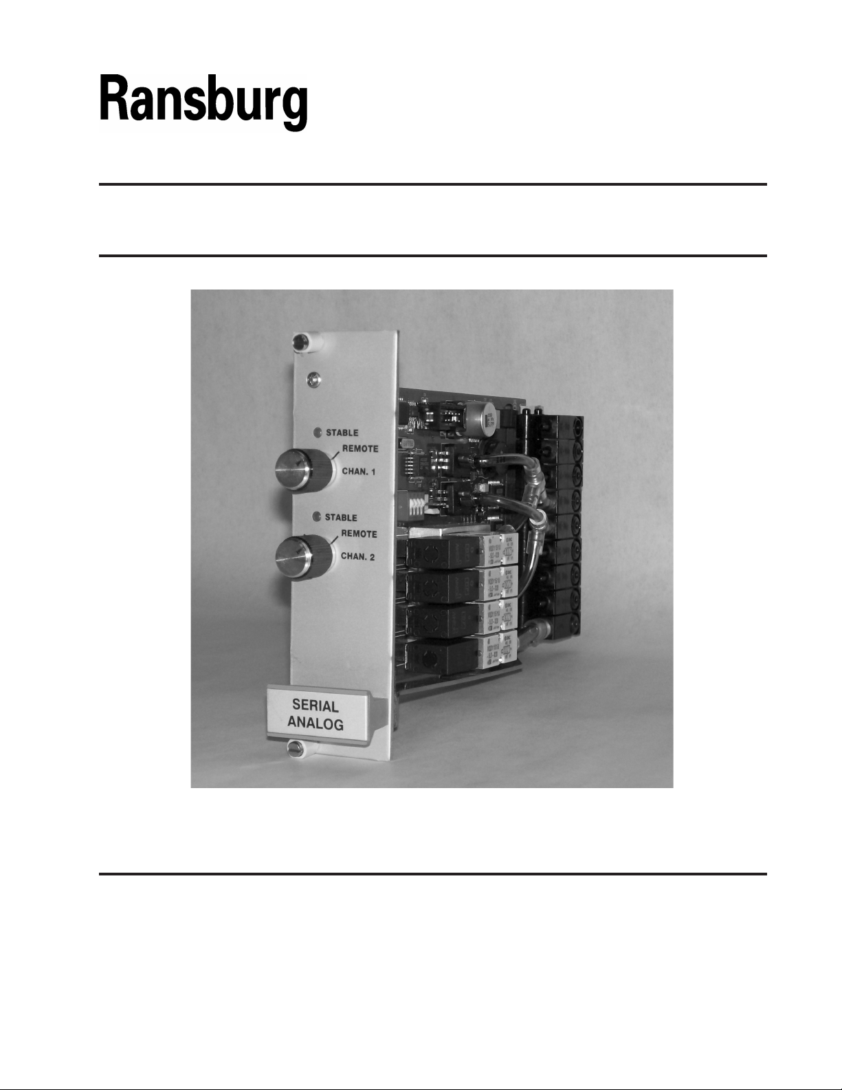
SERIAL ANALOG MODULE
MODEL: A11012
IMPORTANT: Before using this equipment, carefully
read SAFETY PRECAUTIONS, starting on page 1,
and all instructions in this manual. Keep this Service
Bulletin for future reference.
Service Manual Price: $20.00 (U.S.)

LN-9258-07.2

CONTENTS
SAFETY:
Serial Analog Module - Contents
PAGE
1-4
SAFETY PRECAUTIONS...........................................................................................................
HAZARDS/SAFEGUARDS........................................................................................................
INTRODUCTION:
GENERAL DESCRIPTION.........................................................................................................
SPECIFICATIONS......................................................................................................................
INSTALLATION:
CONNECTIONS.........................................................................................................................
ELECTRICAL INTERFACE........................................................................................................
PNEUMATIC SCHEMATIC..........................................................................................
TOP ASSEMBLY.........................................................................................................................
OPERATION:
SW4 SWITCH CONFIGURATION.............................................................................................
JUMPER CONFIGURATION.....................................................................................................
DIGITAL OUTPUT JUMPER TABLE.........................................................................................
REPLACEMENT / UPGRADE OF ANALOG MODULE............................................................
1
2-4
5-6
5
6
7-10
7
8
9
10
11-14
11
12
13
14
WARRANTY POLICIES:
ANALOG MODULE WARRANTY.............................................................................................. 15
15
LN-9258-07.2
Serial Analog Module - Safety
SAFETY
SAFETY PRECAUTIONS
Before operating, maintaining or servicing any
Ransburg electrostatic coating system, read and
understand all of the technical and safety literature for your Ransburg products. This manual
contains information that is important for you to
know and understand. This information relates to
USER SAFETY and PREVENTING EQUIPMENT
PROBLEMS. To help you recognize this information, we use the following symbols. Please pay
particular attention to these sections.
A WARNING! states information to alert you to a
situation that might cause serious injury if instructions are not followed.
A CAUTION! states information that tells how to
prevent damage to equipment or how to avoid a
situation that might cause minor injury.
A NOTE is information relevant to the procedure
in progress.
While this manual lists standard specications and
service procedures, some minor deviations may be
found between this literature and your equipment.
Differences in local codes and plant requirements,
material delivery requirements, etc., make such
variations inevitable. Compare this manual with
your system installation drawings and appropriate
Ransburg equipment
manuals to reconcile such differences.
W A R N I N G
!
> The user MUST read and be familiar
with the Safety Section in this manual
and the Ransburg safety literature therein
identied.
> This manual MUST be read and thoroughly
understood by ALL personnel who operate,
clean or maintain this equipment! Special
care should be taken to ensure that the
WARNINGS and safety requirements for
operating and servicing the equipment are
followed. The user should be aware of and
adhere to ALL local building and re codes
and ordinances as well as NFPA-33 SAFETY
STANDARD, prior to installing, operating,
and/or servicing this equipment.
W A R N I N G
!
> The hazards shown on the following page
may occur during the normal use of this
equipment. Please read the hazard chart
beginning on page 2.
Careful study and continued use of this manual will
provide a better understanding of the equipment
and process, resulting in more efcient operation, longer trouble-free service and faster, easier
troubleshooting. If you do not have the manuals
and safety literature for your Ransburg system,
contact your local Ransburg representative or
Ransburg.
1
LN-9258-07.2
Serial Analog Module - Safety
AREA
Tells where hazards
may occur.
Spray Area
HAZARD
Tells what the hazard is.
Fire Hazard
Improper or inadequate operationing and maintenance pro-
cedures will cause a re hazard.
Protection against inadvertent
arcing that is capable of causing
re or explosion is lost if any safety
interlocks are disabled during operation. Frequent power supply
shutdown indicates a problem in
the system requiring correction.
SAFEGUARDS
Tells how to avoid the hazard.
Fire extinguishing equipment must be present in the
spray area and tested periodically.
Spray areas must be kept clean to prevent the accumulation of combustible residues.
Smoking must never be allowed in the spray area.
The high voltage supplied to the atomizer must be
turned off prior to cleaning, ushing or maintenance.
When using solvents for cleaning:
Those used for equipment ushing should have ash
points equal to or higher than those of the coating
material.
Those used for general cleaning must have ash
points above 100°F (37.8°C).
Spray booth ventilation must be kept at the rates
required by NFPA-33, OSHA, and local codes. In ad dition, ventilation must be maintained during cleaning
operations using ammable or combustible solvents.
Electrostatic arcing must be prevented.
Test only in areas free of combustible material.
Testing may require high voltage to be on, but only
as instructed.
Non-factory replacement parts or unauthorized
equipment modications may cause re or injury.
If used, the key switch bypass is intended for use
only during setup operations. Production should
never be done with safety interlocks disabled.
Never use equipment intended for use in waterborne
installations to spray solvent based materials.
The paint process and equipment should be set up
and operated in accordance with NFPA-33, NED,
and OSHA requirements.
LN-9258-07.2
2
Serial Analog Module - Safety
AREA
Tells where hazards
may occur.
General Use and Maintenance
Electrical
Equipment
HAZARD
Tells what the hazard is.
Improper operation or maintenance may create a hazard.
Personnel must be properly
trained in the use of this equip-
High voltage equipment is utilized.
Arcing in areas of ammable or
combustible materials may oc-
cur. Personnel are exposed to
high voltage during operation and
maintenance.
Protection against inadvertent
arcing that may cause a re or
explosion is lost if safety circuits
are disabled during operation.
Frequent power supply shut-down
indicates a problem in the system
which requires correction.
An electrical arc can ignite coat-
ing materials and cause a re or
explosion.
SAFEGUARDS
Tells how to avoid the hazard.
Personnel must be given training in accordance with
the requirements of NFPA-33.
Instructions and safety precautions must be read and
understood prior to using this equipment.
Comply with appropriate local, state, and national
codes governing ventilation, re protection, operation maintenance, and housekeeping. Reference
OSHA, NFPA-33, and your insurance company
The power supply, optional remote control cabinet,
and all other electrical equipment must be located
outside Class I or II, Division 1 and 2 hazardous
areas. Refer to NFPA-33.
Turn the power supply OFF before working on the
equipment.
Test only in areas free of ammable or combustible
material.
Testing may require high voltage to be on, but only
as instructed.
Production should never be done with the safety
circuits disabled.
Before turning the high voltage on, make sure no
objects are within the sparking distance.
3
LN-9258-07.2

Serial Analog Module - Safety
AREA
Tells where hazards
may occur.
Spray Area /
High Voltage Equipment
HAZARD
Tells what the hazard is.
This is a high voltage device that
can produce electrical arcs capable of igniting coating materials.
SAFEGUARDS
Tells how to avoid the hazard.
Parts being sprayed must be supported on conveyors or hangers and be grounded. The resistance
between the part and ground must not exceed 1
megohm. (Reference NFPA-33.)
A safe distance must be maintained between the
parts being coated and the atomizer bell. A distance
of at least 1-inch for each 10kV of power supply
output voltage is required at all times.
Parts must be supported so that they will not swing
and reduce the clearance specied above.
All electrically conductive objects in the spray area,
with the exception of those objects required by the
process to be at high voltage, must be grounded.
Unless specically approved for use in hazardous
locations, the power supply and other electrical
equipment must not be used in Class I, Division 1
or 2 locations.
LN-9258-07.2
4

Serial Analog Module - Introduction
INTRODUCTION
GENERAL DESCRIPTION
Figure 1: Serial Analog Module
The Serial Analog Module is a plug-in electro-
pneumatic control board designed to t standard
racks. The module has two independent pressure
control channels. Each channel adjusts the output
pressure proportionally to the voltage input.
The Serial Analog Module is congured for output
pressure bleed on power down. It has a normally
closed valve on the supply and a normally open
valve on the exhaust; the output will therefore vent
to atmosphere on power failure or power down.
Remote pressure sensing is standard on -01
Modules. This is achieved by connecting the
transducer sense pneumatic line to the input
side of external devices. Pressure inaccuracies
of devices such as pilot regulators are therefore
compensated by means of closed-loop feedback.
On both channels, pressure transducer output
is pinned-out through the electrical connector.
These signals may be used to drive a meter or to
provide computer-control feedback. In addition,
there is a digital output for each channel; the logic
level is low when the pressure controller is in a
stable state.
On the front panel, LED's indicate when each
channel is stable. Front panel potentiometers
provide manual control of pressure output. A
status signal is provided giving a logic low output
when the panel controls are activated. This can
alert the controller when the module is in the local/
manual mode.
When one output is used to pilot a volume booster
(regulator), the volume booster must have a
non-bleed pilot, such as P/N: A11111.00. Use
of a volume booster with a bleed pilot will cause
uctuating output pressure. When using the Serial Analog Module for a retro-t application, refer
to the last page of Operation section for details.
Pneumatic connections are made through a plugin edge connector which eliminates the need for
pneumatic ttings. Electrical connections are
achieved with a DIN 41612-B connector.
5
LN-9258-07.2

Serial Analog Module - Introduction
SPECIFICATIONS
Environmental / Physical
Temp. Operating: 0° to 55°C
Storage: -40°C to 85°C
Humidity: 95% Non-Condensing
Size: 100 x 160mm
Eurocard module,
35mm wide
Pneumatic
Supply Pressure: 100 psig max.
Pressure Output: 0 to input pressure
Filtration: 40 micron
Power Loss
Protection: Exhausts to atmosphere
(Fail Bleed)
Electrical Input
Input Signal: Analog 0-10 VDC,
1-10 VDC or 4-20 mA
(See "Switch Conguration Chart" in the "Installation"
section for conguration.)
Input Impedance
Voltage Mode: 20 kOhm
4-20 mA Mode: 500 Ohms
Dead Band: ±.7 psi
Linearity: 10 to 90 psi, .5% of full
scale max.
Feedback Accuracy: ± 2%
Feedback: 1. Analog, proportional to output
pressure
2. Digital, "Low" when stabilized
3. Digital, "Low" when in manual
or local mode
Electrical Requirements
Supply Voltage: 24 VDC ± 10%
Supply Current:
24 Volt Supply 350 mA max.
FRONT PANEL CONTROLS
Manual Control Options:
260° Rotation; auto control
enabled when fully CCW
Indicator: Green, ON when output pressure
is stable
Status: Low signal when in manual or local
mode; jumper congurable to be either
5 VDC or 24 VDC, 10 mA source and
500 mA sink.
TTL Logic Level - jumper JMP16,
Pins 1 & 2
24 VDC Level - jumper JMP16,
LN-9258-07.2
6

Serial Analog Module - Installation
INSTALLATION
CONNECTIONS
Pneumatic Connections
The Analog Module uses the following pneumatic
edge connector ports:
CH1 Sense 2 (-01 model only)
CH2 Sense 3 (-01 model only)
CH1 Output 4
CH2 Output 5
Supply Input 9 (bottom)
NOTE
> For stable module operation, the tubing
connected to the pneumatic outputs must
be 35 ft. long (for 5/32" tubing).
Electrical Connections
The Analog Air control Modules uses a DIN 41612
B connector. Pin assignments are as listed below.
ELECTRICAL CONNECTIONS
Backplane TerminalSignal Name
CH1 Analog Input
CH2 Analog Input
CH1 Analog Output
CH2 Analog Output
CH1 Digital, Out, Stable
CH2 Digital, Out, Stable
CH1 Digital, Out, Local
CH2 Digital, Out, Local
V1
V4
V3
V6
V2
V5
V7
V8
C A U T I O N
!
> It is extremely important to prevent con-
tamination of the valves and air passages
inside the module. Adhering to the speci-
cations of 100 psig max. and 40 micron
ltration on the supply air is critical. Since
the valve can also be contaminated through
the output port, ltration is recommended
on output lines also.
Connections
The Analog Module plugs into the 78147 Mother
Board (74847 for Retrot Applications) which
takes one quarter of a 19" rack. Three slots are
available for Analog Modules. Besides canbus
communi-cation to the Node Adapter through
motherboard terminals J4, discrete communication
is accomplished through motherboard terminals
J5, J8, or J11.
7
LN-9258-07.2

ELECTRICAL INTERFACE
Analog inputs and outputs are referenced to power ground.
Serial Analog Module - Installation
LN-9258-07.2
Figure 2: Electrical Block Diagram
8

Analog Module - Installation
PNEUMATIC SCHEMATIC
Figure 3: Pneumatic Schematic
9
LN-9258-07.2

TOP ASSEMBLY
Serial Analog Module - Installation
Figure 4: Top Assembly
C A U T I O N
!
> When removing and replacing electronic
components such as the control modules
in Ransburg systems, it is extremely important that the power to the rack is off. The
electronic components can be damaged if
the cards are unplugged or installed with
power on the rack.
C A U T I O N
!
> When removing and replacing electronic
components such as the control modules in
Ransburg systems, it is extremely important
that antistatic precautions be observed. Antistatic bags must be used to store boards
when not in use. Personnel working with
these cards must be free of any static charge
and must be grounded to prevent buildup
of charge. Equipment used for installation
or removal of the cards must be grounded
or be rated as anti-static type material. The
electronic components can be damaged if
subjected to stray static charges.
LN-9258-07.2
10

Serial Analog Module - Operation
OPERATION
The Serial Analog Module provides a pneumatic
pressure signal output which is proportional to the
voltage input. Each module contains two channels
of control. The voltage input can be provided by
various methods; by a front panel control, by an
external 1-10 VDC signal, an external 0-10 VDC,
or external 4-20 mA signal. The front panel control
has a detent at full CCW. In this detent position,
the output responds to the external voltage input.
When this control is rotated CW from this detent,
the output responds to the position of the front panel
control. A "Local" signal is provided to indicate
that the output is controlled by the front panel. A
"Stable" front panel indicator and signal output
indicate that the output pressure has reached the
level set by the input signal.
NOTE
> Before installing module, make sure the
o-rings (7554-03), located on the edge
connector of each pneumatic valve, are
in place and fully seated. Prior to installing, put a small amount of lubricant on the
surface of each o-ring to prevent shearing
when installing.
W A R N I N G
!
SW4 SWITCH
CONFIGURATION
1. "Open" position for pilot lines less than 50-ft.
of 5/32-inch tubing. "Closed" (opposite the
open position) for pilot lines more than 50-ft.
of 5/32-inch tubing.
2. Future Use
3. Future Use
4. "Open" position for 0-10 VDC remote input in
voltage mode.
"Closed" (opposite the open position) for 1-10
VDC remote input in voltage mode.
> Do not use lubricants that contain sili-
cone.
11
NOTE
When one output is used to pilot a volume booster
(regulator), the volume booster must have a nonbleed pilot, such as P/N: A11111.00. Use of a
volume booster with a bleed pilot will cause uctuating output pressure. When using the Serial
Analog Module for a retro-t application, refer to
the last page of this Operation section for details.
LN-9258-07.2

JUMPER CONFIGURATION
Analog Input
Analog Output
Serial Analog Module - Installation
LN-9258-07.2
12

Serial Analog Module - Operation
DIGITAL OUTPUT JUMPER TABLE
13
LN-9258-07.2

Serial Analog Module - Installation
REPLACEMENT / UPGRADE OF
75118-01 ANALOG MODULE WITH
A11012-00 SERIAL ANALOG MODULE
Note: The Serial Analog Module part number A11012-00 will regulate the output pressure from 10 to 90 psi.
Operation outside of these limits is not recommended.
This procedure is only valid for systems using Watts brand pilot operated regulators (volume boosters) model
R119. It describes how to convert the pilot regulator to a non-bleed pilot, X71 model. The model number is
listed on the side label. See picture below:
TOP DIAPHRAGM
PART NUMBER LABEL IN ONE OF
THESE 2 LOCATIONS
Failure to follow the instructions below will result in uctuating air pressure out of the Serial Analog module.
Due to a difference in regulators, the R119 pilot operated regulator either needs to be replaced with a non-
bleed X71 model, or the top diaphragm must be replaced. A new pilot operated regulator can be ordered
with the X71 sufx or the non-bleed diaphragm for the installed pilot regulator can be obtained from Parker
Pneumatics / Watts FluidAir at (269) 629-5575. For the correct part number, reference the table below:
Existing Pilot Regulator Port Size Diaphragm to Convert to X71 Maximum Air Flow
R119-02J 1/4" RK118-X20Y 100 SCFM
R119-03J 3/8" RK118-X20Y 110 SCFM
R119-04J 1/2" RK118-X20A 150 SCFM
Diaphragm replacement procedure
1. Remove the top screws and remove the old diaphragm. Replace with the new diaphragm and torque
screws to 25 +/- 5 in/lbs.
2. Place Serial Analog Module switch SW4, switch 4 in the closed (opposite the open) position. This
sets the input and output voltages to 1-10 Vdc to duplicate the input voltage of the replaced Analog
module.
3. Install the new Serial Analog Module and lock the quarter turn screws on the top and bottom of the
module.
4. Run a ghost program to test the unit. If uctuations in the air pressure are observed, increase the pi-
lot line length as noted below:
if using 5/32" pilot line, increase to 35’ long
if using ¼” pilot line, increase to 14’ long
LN-9258-07.2
Any additional uctuations in air pressures may be caused by air leaks between the air control mother
board and the pilot operated regulator. Inspect and eliminate any leaks found.
14

Serial Analog Module - Warranty Policies
WARRANTY POLICIES
LIMITED WARRANTY
Ransburg will replace or repair without charge any
part and/or equipment that fails within the specied
time (see below) because of faulty workmanship
or material, provided that the equipment has been
used and maintained in accordance with Ransburg’s written safety and operating instructions,
and has been used under normal operating condi-
tions. Normal wear items are excluded.
THE USE OF OTHER THAN RANS-BURG
APPROVED PARTS VOIDS ALL WARRANTIES.
SPARE PARTS: One hundred and eighty (180)
days from date of purchase, except for rebuilt
parts (any part number ending in “R”) for which
the warranty period is ninety (90) days.
EQUIPMENT: When purchased as a complete
unit, (examples: guns, power supplies, control
units, etc.), is one (1) year from date of purchase.
WRAPPING THE APPLICATOR, ASSOCI-ATED
VALVES AND TUBING, AND SUPPORTING
HARDWARE IN PLASTIC, SHRINK-WRAP, OR
ANY OTHR NON-APPROVED COVERING, WILL
VOID THIS WARRANTY.
RANSBURG’S ONLY OBLIGATION UNDER THIS
WARRANTY IS TO REPLACE PARTS THAT
HAVE FAILED BECAUSE OF FAULTY WORKMANSHIP OR MATE-RIALS. THERE ARE NO
IMPLIED WARRANTIES NOR WARRANTIES
OF EITHER MERCHANTABILITY OR FITNESS
FOR A PARTICULAR PURPOSE. RANSBURG
ASSUMES NO LIABILITY FOR INJURY, DAMAGE TO PROPERTY OR FOR CONSEQUENTIAL DAMAGES FOR LOSS OF GOODWILL OR
PRODUCTION OR INCOME, WHICH RESULT
FROM USE OR MISUSE OF THE EQUIPMENT
BY PURCHASER OR OTHERS.
EXCLUSIONS:
If, in Ransburg’s opinion the warranty item in
question, or other items damaged by this part
was improperly installed, operated or maintained,
Ransburg will assume no responsibility for repair or
replacement of the item or items. The purchaser,
therefore will assume all responsibility for any
cost of repair or replacement and service related
costs if applicable.
15
LN-9258-07.2

MANUAL CHANGE SUMMARY
This manual was published to replace Service
Manual LN-9258-07.1 Serial Analog Module, to
make the following changes:
1. Revised Pressure Output to "0 to input pressure"
in the Pneumatic section of SPECIFICATIONS.
2. Revised Linearity to "10-90 psi" in the Electrical
Input section of SPECIFICATIONS.
3. Revised Pneumatic Connections table in
Connections section of INSTALLATION.
4. Added "REPLACEMENT UPGRADE OF
75118-01 ANALOG MODULE WITH A11012-00
SERIAL ANALOG MODULE" in OPERATION
section.
5. Revised "Figure 2: Block Diagram" in the
INSTALLATION section.
LN-9258-07.2

Service Manual Price: $20.00 (U.S.)
Manufacturing
1910 North Wayne Street
Angola, Indiana 46703-9100
Telephone: 260/665-8800
Fax: 260/665-8516
www.ransburg.com
Technical/Service Assistance Telephone: 800/ 626-3565 Fax: 419/ 470-2040
Telephone: 800/ 233-3366 Fax: 419/ 470-2071
Technical Support Representative will direct you to the appropriate telephone number for
ordering Spare Parts.
© 2013 Ransburg. All rights reserved.
Models and specications subject to change without notice.
Form No. LN-9258-07.2
Litho in U.S.A.
04/13
 Loading...