

SERVICE MANUAL
CS-02-01.10
(Replaces CS-02-01.9)
January - 2013
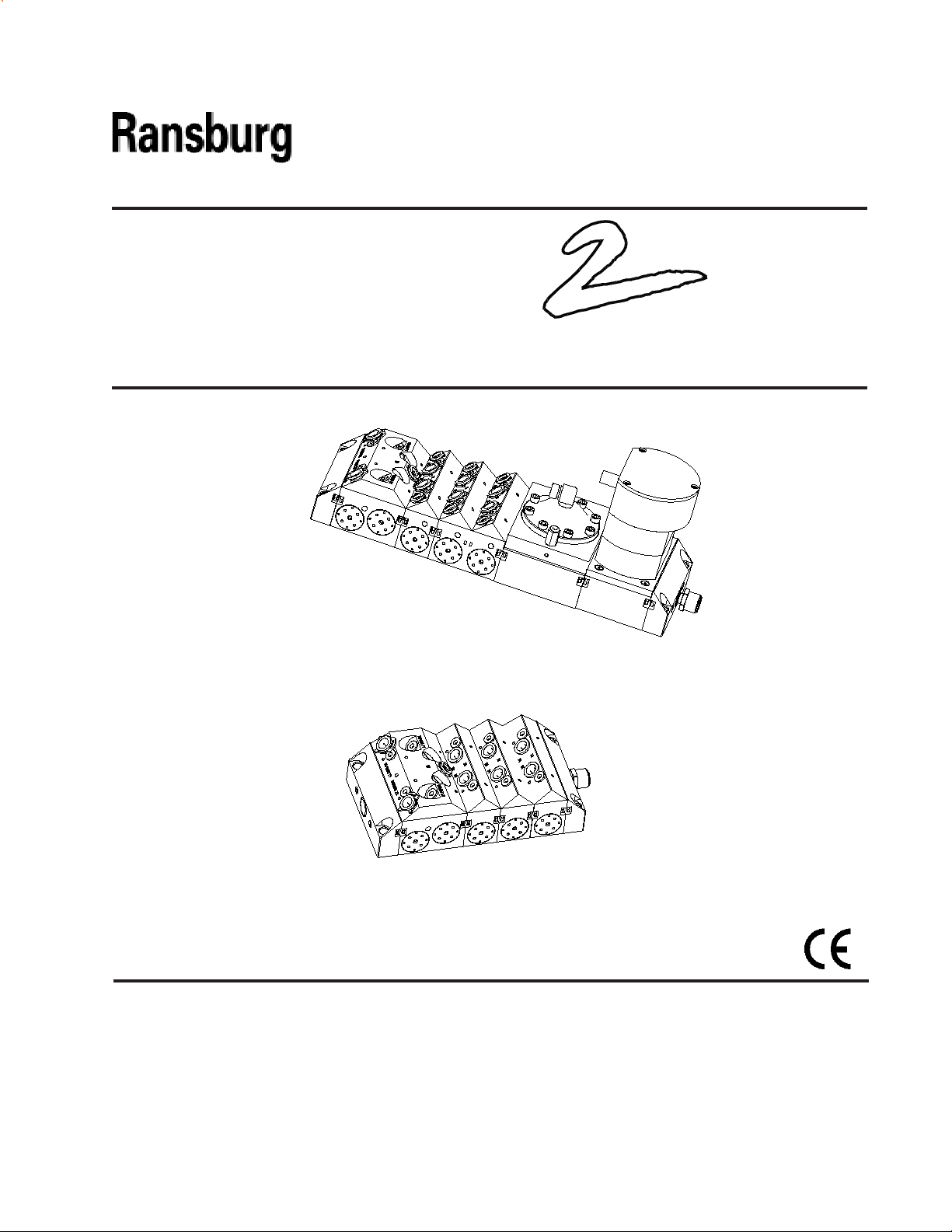
MCV
COLLET SERIES
MODULAR COLOR CHANGER
MODELS: A10800XX Metric
A11077-XX - English
IMPORTANT: Before using this equipment, carefully
read SAFETY PRECAUTIONS, starting on page 1, and all
instructions in this manual. Keep this Service Manual
for future reference.
Service Manual Price: $30.00 (U.S.)

NOTE: This manual has been changed from CS-02-01.9 to revision CS-02-01.10. Reasons for
this change are noted under “Manual Change Summary” inside the back cover of this
manual.
CONTENTS
MCV 2 Collet Series Color Changer - Contents
PAGE
SAFETY:
SAFETY PRECAUTIONS...........................................................................................................
HAZARDS / SAFEGUARDS.......................................................................................................
INTRODUCTION:
DESCRIPTIONS.........................................................................................................................
SPECIFICATIONS......................................................................................................................
REGULATOR PERFORMANCE.................................................................................................
MCV 2 PRE-ENGINEERED COLOR CHANGER
ASSEMBLIES / PARTS LIST ..... ...............................................................................................
MCV 2 PRE-ENGINEERED COLOR CHANGER
MODEL IDENTIFICATION (METRIC) / PARTS LIST................................................................
MCV 2 PRE-ENGINEERED COLOR CHANGER
ASSEMBLIES - PARTS LIST (ENGLISH)..................................................................................
MCV 2 PRE-ENGINEERED COLOR CHANGER
MODEL IDENTIFICATION (ENGLISH) / PARTS LIST..............................................................
INSTALLATION:
MCV 2 INSTALLATION PROCEDURES....................................................................................
1-4
1
2-3
5-14
5
5
6
7-8
8-10
11
11-13
15-16
15
OPERATION:
OPERATING.............................................................................................................................
DIMENSIONS - METRIC (FRACTION) AND PROPOSED
HOOK-UP FOR 8-COLORS......................................................................................................
MAINTENANCE:
GENERAL MAINTENANCE........................................................................................................
REMOVING AND REINSTALLING A VALVE BLOCK
FROM A STACK.........................................................................................................................
REGULATOR DISASSEMBLY / REASSEMBLY
PROCEDURE.............................................................................................................................
TEST AND CHECKOUT PROCEDURE FOR
COLOR CHANGER....................................................................................................................
(Continued On Next Page)
17-18
17
18
19-26
19-21
21
22-23
24-25

MCV 2 Collet Series Color Changer - Contents
CONTENTS (Cont.)
PARTS IDENTIFICATION :
A10800 (METRIC) AND A11077 (ENGLISH) MCV 2
COLOR CHANGER ASSEMBLIES / PARTS LIST....................................................................
A10717 (METRIC) AND A11080 (ENGLISH) BELL /
BLOCK WASH ASSEMBLIES / PARTS LIST............................................................................
A11788 BELL / BLOCK WASH ASSEMBLY (METRIC) PARTS LIST.......................................
A11080 BELL / BLOCK WASH ASSEMBLY (ENGLISH) PARTS LIST.....................................
A10727 (METRIC) AND A10953 (ENGLISH) 2-COLOR
VALVE - CIRCULATING ASSEMBLY / PARTS LIST................................................................
A10726 (METRIC) AND A10954 (ENGLISH) 2-COLOR
VALVE - DAISY CHAIN / PARTS LIST......................................................................................
A10733 (METRIC) AND A10955 (ENGLISH) 2-COLOR
VALVE - DEAD HEAD / PARTS LIST........................................................................................
A10729 (METRIC) AND A10960 (ENGLISH) 4-COLOR
VALVE CIRCULATING ASSEMBLY / PARTS LIST..................................................................
A10728 (METRIC) AND A10961 (ENGLISH) 4-COLOR
VALVE - DAISY CHAIN ASSEMBLY / PARTS LIST..................................................................
A10732 (METRIC) AND A10962 (ENGLISH) 4-COLOR
VALVE - DEAD HEAD ASSEMBLY / PARTS LIST....................................................................
A10725 REGULATOR ASSEMBLY / PARTS LIST....................................................................
A10720-01/02 FLOW METER BLOCK ASSEMBLY / PARTS LIST...........................................
A10826-XX STAND ALONE BELL / BLOCK WASH ASSEMBLY
(METRIC & ENGLISH) / PARTS LIST.......................................................................................
A10827-00 STAND ALONE REGULATOR ASSEMBLY / PARTS LIST....................................
A10828-XX STAND ALONE FLOW METER ASSEMBLY
(RF-1 FIBER OPTIC) / PARTS LIST..........................................................................................
A10999-00 STAND ALONE FLOW METER ASSEMBLY
(AW) / PARTS LIST....................................................................................................................
78949-00 VALVE AND 77367-00 SEAT REPLACEMENT PARTS...........................................
77620-00 VALVE PLUG KIT (OPTIONAL).................................................................................
RECOMMENDED SPARE PARTS ...........................................................................................
PAGE
27-57
27-31
32-33
34
35
37-28
39-40
41-42
43-44
45-46
47-48
49-50
51
52
53
54
55
56
56
57
WARRANTY POLICIES:
LIMITED WARRANTY.................................................................................................................
59
59

MCV 2 Collet Series Color Changer - Contents
MCV 2 Collet Series Color Changer - Safety
SAFETY
SAFETY PRECAUTIONS
Before operating, maintaining or servicing any Ransburg electrostatic coating system, read and understand all of the technical and safety literature for your
Ransburg products. This manual contains information
that is important for you to know and understand. This
information relates to USER SAFETY and PREVENTING
EQUIPMENT PROBLEMS. To help you recognize this
information, we use the following symbols. Please
pay particular attention to these sections.
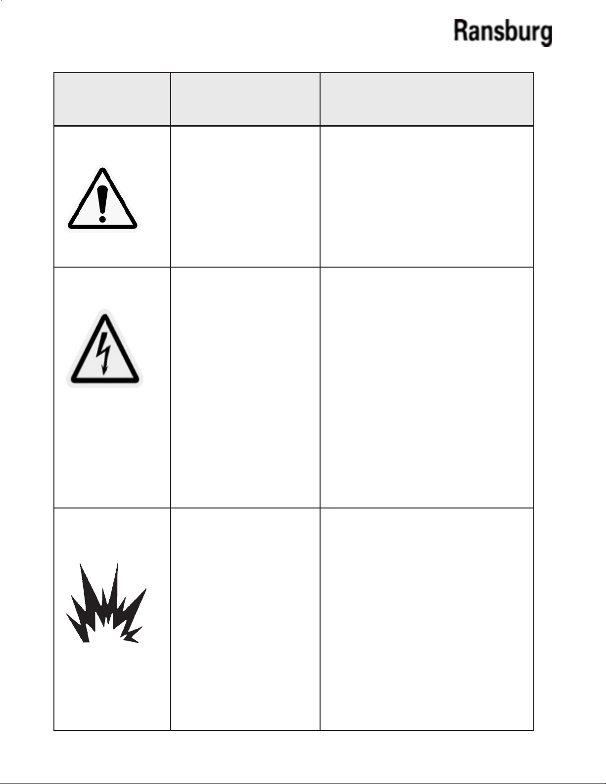
A WARNING! states information to alert you to a situation that might cause serious injury if instructions
are not followed.
A CAUTION! states information that tells how to
prevent damage to equipment or how to avoid a
situation that might cause minor injury.
A NOTE is information relevant to the procedure in
progress.
While this manual lists standard specications and
service procedures, some minor deviations may be
found between this literature and your equipment.
Dierences in local codes and plant requirements,
material delivery requirements, etc., make such
variations inevitable. Compare this manual with
your system installation drawings and appropriate
Ransburg equipment manuals to reconcile such
dierences.
!
> The user MUST read and be familiar with the
Safety Section in this manual and the Ransburg
safety literature therein identied.
> This manual MUST be read and thoroughly
understood by ALL personnel who operate,
clean or maintain this equipment! Special care
should be taken to ensure that the WARNINGS
and safety requirements for operating and
servicing the equipment are followed. The
user should be aware of and adhere to ALL
local building and re codes and ordinances
as well as NFPA-33 SAFETY STANDARD, prior
to installing, operating, and/or servicing this
equipment.
!
> The hazards shown on the following page
may occur during the normal use of this equipment. Please read the hazard chart beginning
on page 2.
W A R N I N G
W A R N I N G
Careful study and continued use of this manual will
provide a better understanding of the equipment and
process, resulting in more ecient operation, longer
trouble-free service and faster, easier troubleshooting.
If you do not have the manuals and safety literature
for your Ransburg system, contact your local Ransburg
representative or Ransburg.
1 CS-02-01.10
MCV 2 Collet Series Color Changer - Safety
AREA
Tells where hazards
may occur.
Spray Area
HAZARD
Tells what the hazard is.
Fire Hazard
Improper or inadequate operation and maintenance procedures
will cause a re hazard.
Protection against inadvertent
arcing that is capable of causing
re or explosion is lost if any safety
interlocks are disabled during
operation. Frequent power supply
shutdown indicates a problem in
the system requiring correction.
SAFEGUARDS
Tells how to avoid the hazard.
Fire extinguishing equipment must be present in the
spray area and tested periodically.
Spray areas must be kept clean to prevent the accumulation of combustible residues.
Smoking must never be allowed in the spray area.
The high voltage supplied to the atomizer must
be turned o prior to cleaning, ushing or maintenance.
When using solvents for cleaning:
Those used for equipment ushing should have ash
points equal to or higher than those of the coating
material.
Those used for general cleaning must have ash
points above 100oF (37.8oC).
Spray booth ventilation must be kept at the rates
required by NFPA-33, OSHA, and local codes. In
addition, ventilation must be maintained during
cleaning operations using ammable or combustible
solvents.
Electrostatic arcing must be prevented.
Test only in areas free of combustible material.
Testing may require high voltage to be on, but only
as instructed.
Non-factory replacement parts or unauthorized
equipment modications may cause re or injury.
If used, the key switch bypass is intended for use only
during setup operations. Production should never
be done with safety interlocks disabled.
Never use equipment intended for use in waterborne installations to spray solvent based materials.
The paint process and equipment should be set up
and operated in accordance with NFPA-33, NEC,
and OSHA requirements.
CS-02-01.10
2
MCV 2 Collet Series Color Changer - Safety
AREA
Tells where hazards
may occur.
Ge ne r al Us e an d
Maintenance
Electrical
Equipment
HAZARD
Tells what the hazard is.
Improper operation or mainte nance may create a hazard.
Personnel must be properly trained
in the use of this equipment.
High voltage equipment is utilized.
Arcing in areas of flammable or
combustible materials may occur.
Personnel are exposed to high
voltage during operation and maintenance.
Protection against inadver tent
arcing that may cause a re or explosion is lost if safety circuits are
disabled during operation.
Frequent power supply shut-down
indicates a problem in the system
which requires correction.
An electrical arc can ignite coating materials and cause a fire or
explosion.
SAFEGUARDS
Tells how to avoid the hazard.
Personnel must be given training in accordance with
the requirements of NFPA-33.
Instructions and safety precautions must be read
and understood prior to using this equipment.
Comply with appropriate local, state, and national
codes governing ventilation, re protection, operation maintenance, and housekeeping. Reference
OSHA, NFPA-33, and your insurance company
requirements.
The power supply, optional remote control
cabinet, and all other electrical equipment must
be located outside Class I or II, Division 1 and 2
hazardous areas. Refer to NFPA-33.
Turn the power supply OFF before working on the
equipment.
Test only in areas free of ammable or combustible material.
Testing may require high voltage to be on, but
only as instructed.
Production should never be done with the safety
circuits disabled.
Before turning the high voltage on, make sure no
objects are within the sparking distance.
Explosion Hazard /
Incompatible
Materials
3
Halogenated hydrocarbon solvents for example: methylene
chloride and 1,1,1,-Trichloroethane are not chemically compatible with the aluminum that
might be used in many system
components. The chemical reaction caused by these solvents
reacting with aluminum can
become violent and lead to an
equipment explosion.
Aluminum is widely used in other spray application
equipment - such as material pumps, regulators,
triggering valves, etc. Halogenated hydrocarbon
solvents must never be used with aluminum equipment during spraying, ushing, or cleaning. Read
the label or data sheet for the material you intend
to spray. If in doubt as to whether or not a coating
or cleaning material is compatible, contact your
material supplier. Any other type of solvent may
be used with aluminum equipment.
CS-02-01.10

NOTES
MCV 2 Collet Series Color Changer - Safety
CS-02-01.10
4

MCV 2 Collet Series Color Changer - Introduction
INTRODUCTION
DESCRIPTIONS
The MCV 2 Collet Series Modular Color Changer is a
material valve stack used to control material ow to
an applicator or other material supply equipment.
The stack assembly is made up of several sub-assembled stacks which are then connected together.
The assemblies are available in both Metric and
English tube sizes.
A description of stacks are as follows:
• Bell Wash Module - This may be attached
to the main stack.
• Stand-Alone Bell Wash Module - These may
be mounted separately away from the stack
assembly. An external outlet port is included
to provide a connection to an applicator or
other such device.
• Two and Four Color Block Modules. Both
available in 3 styles: Circulating, Daisy
Chain, and Dead Head.
• Inline DR-2 Regulator with performance
matching the industry standard
Ransburg DR-1 Regulator.
• Flow Meter Module for use with bottom
ported uid ow meters.
SPECIFICATIONS
Electrical / Physical
Operating Pressure:
Fluid: 300 psi maximum
(20.68 bar)
Air: 100 psi maximum
(7 bar)
Fluid Tube Metric:
(Inlet) 10mm ODT
(Circulation) 8mm ODT
(Bell wash) 6mm & 8mm ODT
Fluid Tube Fraction:
(Inlet) 3/8-inch ODT
(Circulation) 5/16-inch ODT
(Bell wash) 5/16-inch ODT
Air Tube Fraction Metric:
(Actuation) 5/32-inch
(4mm) ODT Inlet
Air Actuating Pressure: 75-120 psi
(5.2-8.3 bar)
Maximum Number of Colors: 32
Construction Materials:
Stainless Steel
UHMW
DR-2 Regulator
The 78949-00 microvalve was designed to trigger
up to 2-million cycles. The uid and air sections are
separated by a weep port to prevent contamination
between air and uid.
5
Air Pressures: Variable by Control
(Manual or Automatic)
100 psi (7 bar max.)
Fluid Input: 300 psi (20.7 bar max.)
(10 psi min. above output
pressure)
Fluid Output: Variable by Ratio
Pneumatic Connections
Air Pilot: 1/8-inch NPT (F) Thread
(Cap)
#10-32 (F) Thread (Plate)
Volume of Paint Held
Within Regulator: 5 cc
CS-02-01.10
MCV 2 Collet Series Color Changer - Introduction
0
200
400
600
800
1000
1200
1400
1600
1800
2000
0 10 20 30 40 50 60 70 80 90 100
Flow Rate (cc/min)
Pilot Pressure (psig)
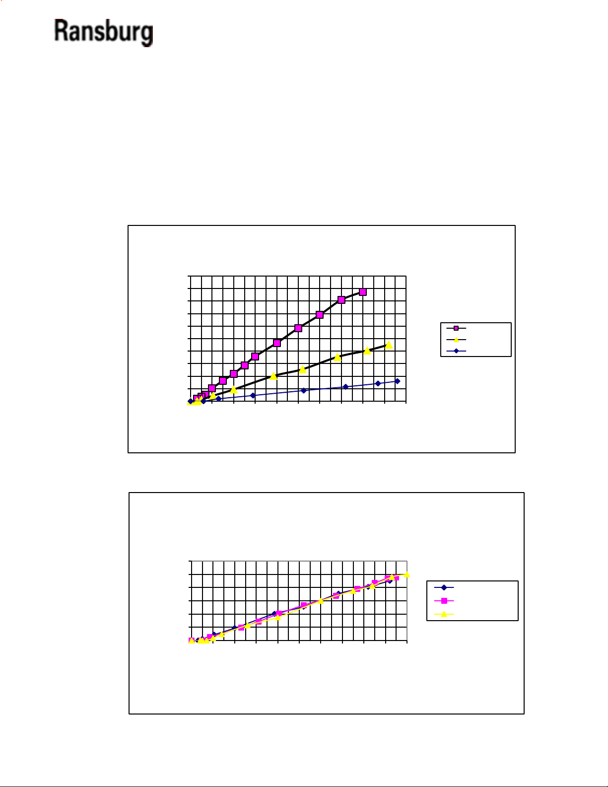
Adjustment Sensitivity-DR-2 Regulator
Pilot Pressure vs. Flow Rate100 psig inlet
22 Sec Ford #4 Viscosity
1/8 Orifice
3/32 orifice
1/16 Orifice
0
200
400
600
800
1000
1200
0 10 20 30 40 50 60 70 80 90 100
Flow Rate (cc/min)
Pilot Pressure (psig)
Adjustment Sensitivity-DR-2 Regulator
.093 Feed Tube
22 Sec. Ford #4 Viscosity
100 psig inlet
200 psig inlet
300 psig inlet
REGULATOR PERFORMANCE
The A10725 regulator performance matches that
of the stand-alone DR-1. Figures X and Y show the
performance curves associated with the A10725
regulator.
CS-02-01.10
Figure X
Figure Y
6
MCV 2 Collet Series Color Changer - Introduction
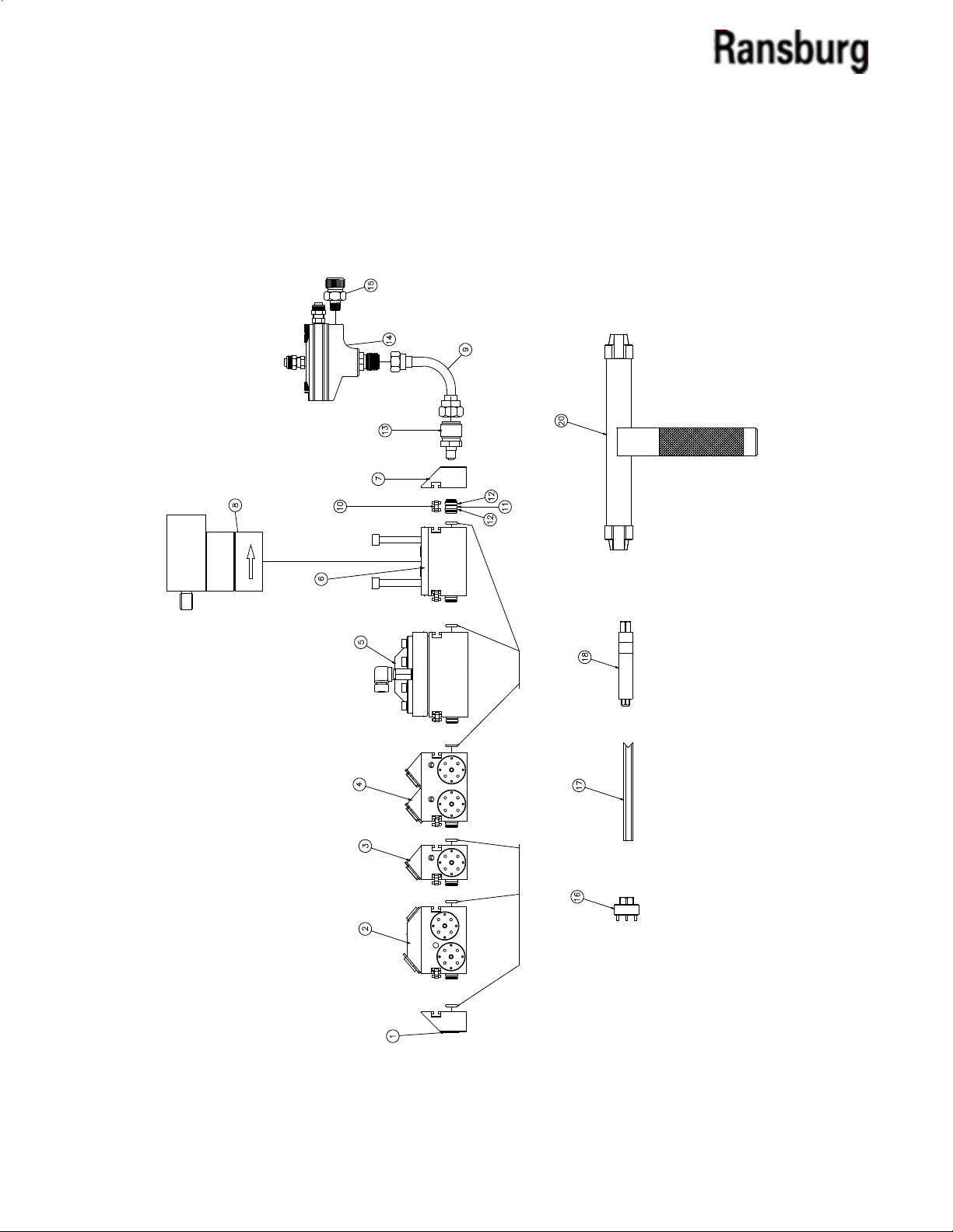
O-RINGS INCLUDED WITH EACH BLOCK ASY.
MCV 2 PREENGINEEREDCOLOR CHANGER ASSEMBLIES
The following is for “pre-engineered” color changer assemblies. Please reference selection chart for the
changer assembly number.
Figure 1: Pre-Engineered Color Changer Assemblies
7
CS-02-01.10
MCV 2 Collet Series Color Changer - Introduction
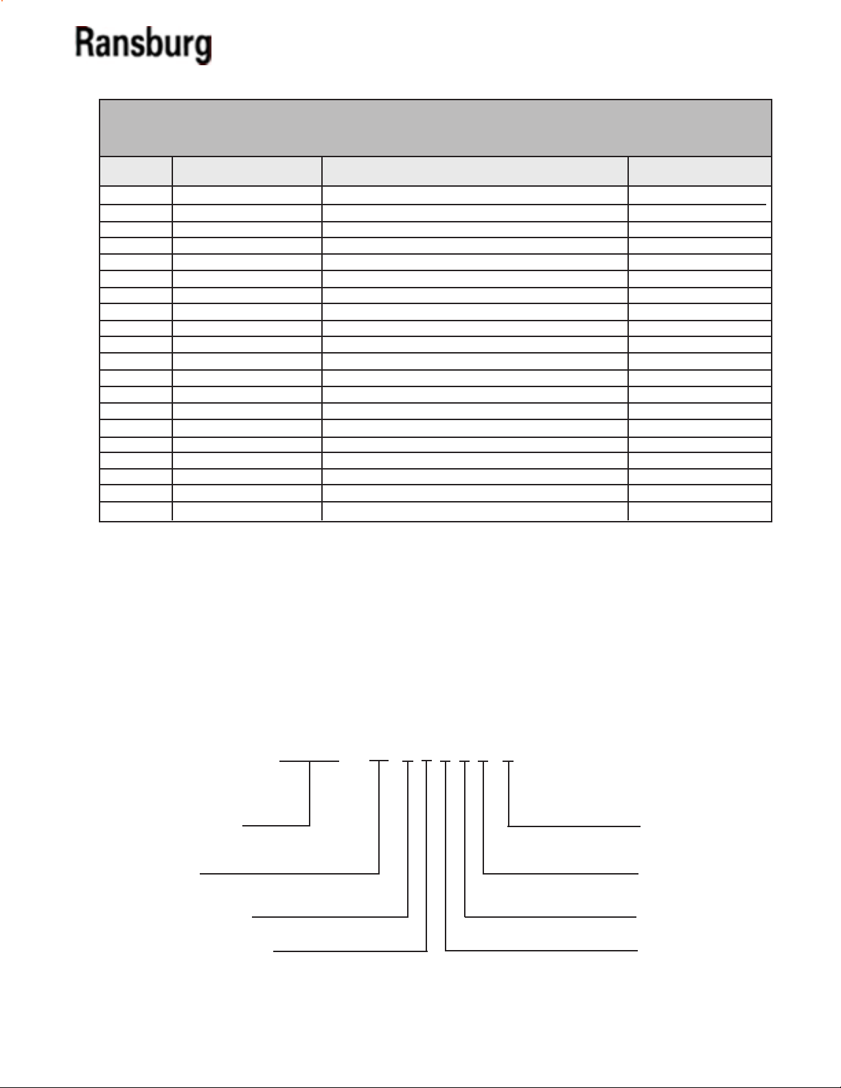
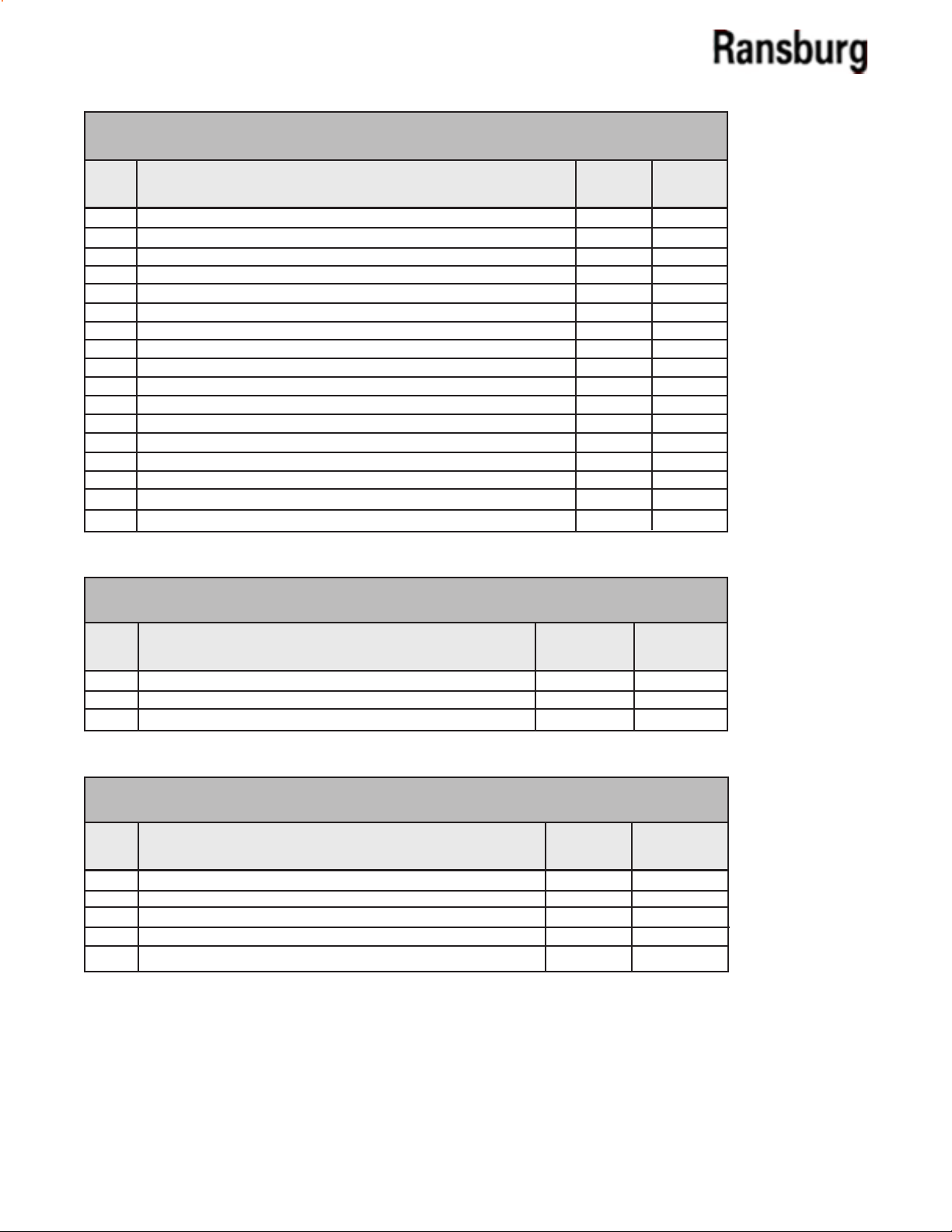
MCV 2 PRE-ENGINEERED COLOR CHANGER ASSEMBLIES PARTS LIST (METRIC) (Figure 1)
Item #
1 A10711-00 Assembly, Plate, Closed End 1
2 See Table C - “Z” Assembly, Bell/Block Wash (Metric) See Table C - “E”
3 See Table B - “R” Assembly, 2-Color Valve Circulating (Metric) See Table AA - “F”
4 See Table B - “S” Assembly, 4-Color Valve Circulating (Metric) See Table AA - “G”
5 See Table V - “X” Assembly, Regulator See Table V - “T”
6 See Table D - “Y” Assembly, Flow Meter Block See Table D - “H”
7 A10712-00 Assembly, Plate Fitting End 1
8 See Table D - “K” Flow Meter See Table D - “J”
9 78069-00 Fluid Regulator Inlet Tube See Table W - “N”
10 77957-00 Retaining Clip, Color Changer 1
11 A10714-00 Fitting, End 1
12 79001-06 O-Ring, Solvent Proof 2
13 78079-00 Fitting, Outlet 1
14 See Table W - “L” Fluid Regulator See Table W - “M”
15 78098-00 Adapter 1/8” NPT (M) X 3/8” NPS (M) See Table W - “P”
16 A10756-00 Tool, Valve Removal 1
17 78078-00 Tool, Retaining Clip Removal 1
18 A10766-00 Tool, Valve Seat Removal 1
19 (Not Used) ---- -20 A10758-00 Tool, Hose Removal 1
(Tool Items #16, 17, 18, and 20 are included with each assembly.)
Part # Description
Qty
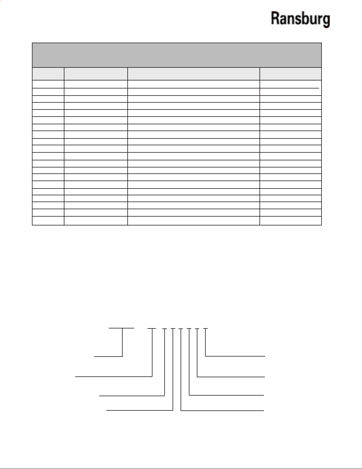
MCV 2 PREENGINEERED COLOR CHANGER ASSEMBLIES
MODEL IDENTIFICATION Metric)
When ordering, use A10800-AA, B, C, D, V, W, or BB as indicated by the Tables AA, B, C, D, V, W, and BB.
Seven characters must follow the basic part number, for example:
A10800 - 06 3 0 2 1 2 1
Fiber Optic
Basic Part Number
Quantity of
Color Valves
Style of Color Valves
Bell/Block Wash Option
(Table AA)
(Table B)
(Table C)
(Table D)
(Table BB)
(Table W)
(Table V)
Cable Length
Outlet - Fluid
Regulator Ratio
Inline - Fluid
Regulator Option
Flow Meter Type
CS-02-01.10
8
MCV 2 Collet Series Color Changer - Introduction
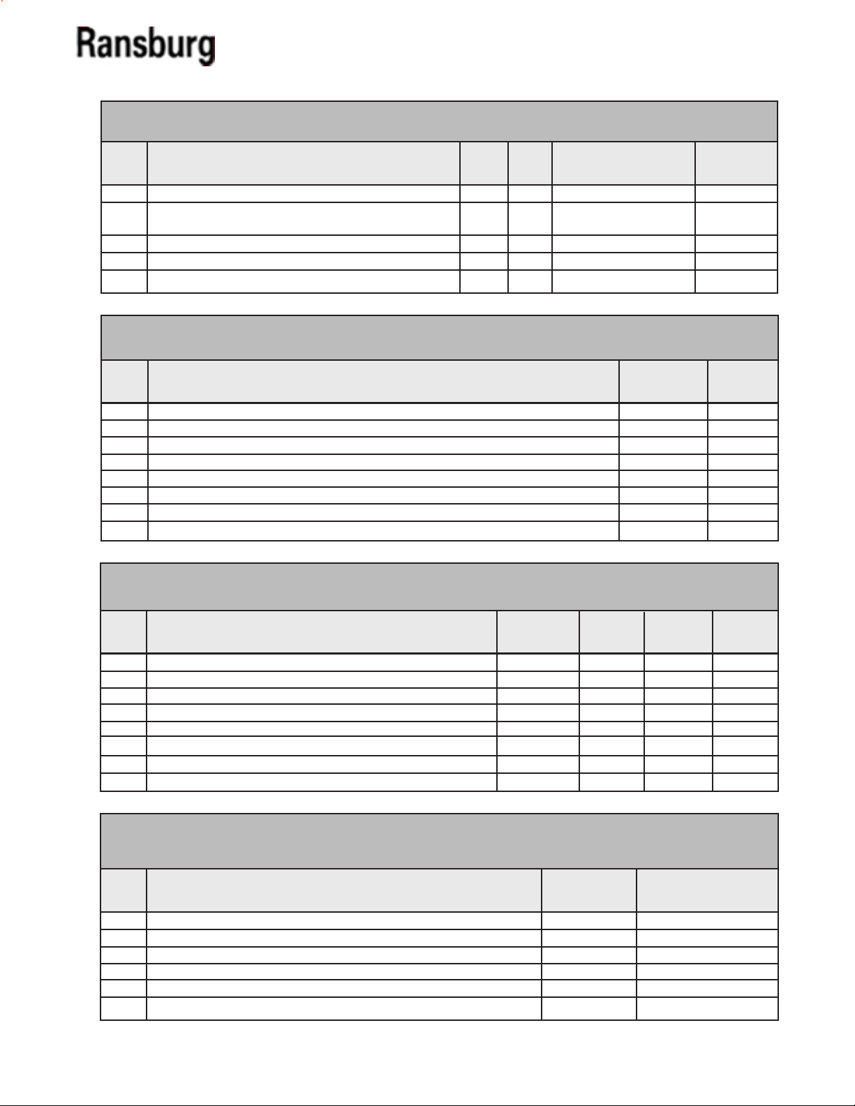
TABLE AA - QUANTITY OF COLOR VALVES (METRIC)
Dash
No.
Description
0-Color - Color Changer
00
2-Color - Color Changer
02
4-Color - Color Changer
04
6-Color - Color Changer
06
8-Color - Color Changer
08
10-Color - Color Changer
10
12-Color - Color Changer
12
14-Color - Color Changer
14
16-Color - Color Changer
16
18-Color - Color Changer
18
20-Color - Color Changer
20
22-Color - Color Changer
22
24-Color - Color Changer
24
26-Color - Color Changer
26
28-Color - Color Changer
28
30-Color - Color Changer
30
32-Color - Color Changer
32
“F”
0
1
0
1
0
1
0
1
0
1
0
1
0
1
0
1
0
“G”
0
0
1
1
2
2
3
3
4
4
5
5
6
6
7
7
8
TABLE B - STYLE OF COLOR VALVES (METRIC)
Dash
No.
Description
Circulating (Metric)
1
Daisy Chain (Metric)
2
Dead Head (Metric)
3
TABLE C - BELL / BLOCK WASH OPTION (METRIC)
Dash
No.
Description
0
No Bell / Block Wash
1
With Both Bell / Block Wash, 8mm Bell Wash
2
With Purge Block Only, 8mm Bell Wash
3
With Both Bell/Block Wash, 6mm Bell Wash
4
With Purge Block Only, 6mm Bell Wash
“R”
A10727-00
A10726-00
A10733-00
“E”
0
1
1
1
1
“S”
A10729-00
A10728-00
A10732-00
“Z”
0
A10717-02
A10717-01
A11788-02
A11788-01
9
CS-02-01.10
MCV 2 Collet Series Color Changer - Introduction
TABLE D - FLOW METER TYPE (METRIC & ENGLISH)
Dash
No.
Description
No Flow Meter
0
Block W/AW Flow Meter Attached -
1
Consult your Sales Rep. for Pick-Up
Block W/RF-1 Fiber Optic Flow Meter Attached
2
AW Block W/No Flow Meter
3
RF-1 Fiber Optic Block W/No Flow Meter
4
“H”
“J”
0
1
1
1
1
0
1
1
0
0
See Table BB - “CC”
“K”
0
75955-06
0
0
TABLE V - INLINE - FLUID REGULATOR OPTION (METRIC & ENGLISH)
Dash
No.
Description
No Outlet Regulator
0
DR-2 - 1:1 Ratio
1
DR-2 - 1:2 Ratio
2
DR-2 - 1:3 Ratio
3
DR-2 - 1:4 Ratio
4
DR-2 - 1:6 Ratio
5
DR-2 - 1:8 Ratio
6
DR-2 - 1:10 Ratio
7
“X”
A10725-01
A10725-02
A10725-03
A10725-04
A10725-06
A10725-06
A10725-08
A10725-10
“Y”
0
A10720-01
A10720-02
A10720-01
A10720-02
“T”
0
1
1
1
1
1
1
1
TABLE W - OUTLET - FLUID REGULATOR RATIO (METRIC & ENGLISH)
Dash
No.
0
1
2
3
4
5
6
7
Description
No Outlet Regulator
DR-1 - 1:1 Ratio
DR-1 - 1:2 Ratio
DR-1 - 1:3 Ratio
DR-1 - 1:4 Ratio
DR-1 - 1:6 Ratio
DR-1 - 1:8 Ratio
DR-1 - 1:10 Ratio
“L”
---74151-11
74151-01
74151-06
74151-02
74151-03
74151-04
74151-05
“M”
0
1
1
1
1
1
1
1
TABLE BB - RF-1 FLOW METER KIT/FIBER OPTIC CABLE LENGTH
(METRIC & ENGLISH)
Dash
No.
Description
RF-1 Flow Meter, Receiver & Cable, Fiber Optic Cable
1
RF-1 Flow Meter, Receiver & Cable, Fiber Optic Cable
2
RF-1 Flow Meter, Receiver & Cable, Fiber Optic Cable
3
RF-1 Flow Meter, Receiver & Cable, Fiber Optic Cable
5
RF-1 Flow Meter, Receiver & Cable, Fiber Optic Cable
4
RF-1 Flow Meter, Receiver & Cable, Fiber Optic Cable
6
“CC”
A11516-15
A11516-25
A11516-50
A11516-65
A11516-75
A11516-100
“N”
0
1
1
1
1
1
1
1
“P”
0
1
1
1
1
1
1
1
“Fiber Optic Cable
Length”
15 Ft.
25 Ft.
50 Ft.
65 Ft.
75 Ft.
100 Ft.
CS-02-01.10
10
MCV 2 Collet Series Color Changer - Introduction
MCV 2 PRE-ENGINEERED COLOR CHANGER ASSEMBLIES PARTS LIST (ENGLISH) (Figure 1)
Item #
1 A10711-00 Assembly, Plate, Closed End 1
2 See Table C - “Z” Assembly, Bell/Block Wash (Metric) See Table C - “E”
3 See Table B - “R” Assembly, 2-Color Valve Circulating (Metric) See Table AA - “F”
4 See Table B - “S” Assembly, 4-Color Valve Circulating (Metric) See Table AA - “G”
5 See Table V - “X” Assembly, Regulator See Table V - “T”
6 See Table D - “Y” Assembly, Flow Meter Block See Table D - “H”
7 A10712-00 Assembly, Plate Fitting End 1
8 See Table D - “K” Flow Meter See Table D - “J”
9 78069-00 Fluid Regulator Inlet Tube See Table W - “N”
10 77957-00 Retaining Clip, Color Changer 1
11 A10714-00 Fitting, End 1
12 79001-06 O-Ring, Solvent Proof 2
13 78079-00 Fitting, Outlet 1
14 See Table W - “L” Fluid Regulator See Table W - “M”
15 78098-00 Adapter 1/8” NPT (M) X 3/8” NPS (M) See Table W - “P”
16 A10756-00 Tool, Valve Removal 1
17 78078-00 Tool, Retaining Clip Removal 1
18 A10766-00 Tool, Valve Seat Removal 1
19 (Not Used) ---- -20 A10758-00 Tool, Hose Removal 1
(Tool Items #16, 17, 18, and 20 are included with each assembly.)
Part # Description
Qty
MCV 2 PREENGINEERED COLOR CHANGER ASSEMBLIES
MODEL IDENTIFICATION English)
When ordering, use A11077-AA, B, C, D, V, W, or BB as indicated by the Tables AA, B, C, D, V, W, and BB.
Seven characters must follow the basic part number, for example:
A11077 - 06 3 0 2 1 2 1
Fiber Optic
Basic Part Number
Quantity of
Color Valves
Style of Color Valves
Bell/Block Wash Option
(Table AA)
(Table B)
(Table C)
(Table BB)
(Table W)
(Table V)
(Table D)
Cable Length
Outlet - Fluid
Regulator Ratio
Inline - Fluid
Regulator Option
Flow Meter Type
11
CS-02-01.10
MCV 2 Collet Series Color Changer - Introduction
TABLE AA - QUANTITY OF COLOR VALVES (ENGLISH)
Dash
No.
Description
00
0 Color - Color Changer
02
2 Color - Color Changer
04
4 Color - Color Changer
06
6 Color - Color Changer
08
8 Color - Color Changer
10
10 Color - Color Changer
12
12 Color - Color Changer
14
14 Color - Color Changer
16
16 Color - Color Changer
18
18 Color - Color Changer
20
20 Color - Color Changer
22
22 Color - Color Changer
24
24 Color - Color Changer
26
26 Color - Color Changer
28
28 Color - Color Changer
30
30 Color - Color Changer
32
32 Color - Color Changer
“F”
0
1
0
1
0
1
0
1
0
1
0
1
0
1
0
1
0
“G”
0
0
1
1
2
2
3
3
4
4
5
5
6
6
7
7
8
TABLE B - STYLE OF COLOR VALVES (ENGLISH)
Dash
No.
1
2
3
Description
Circulating (English)
Daisy Chain (English)
Dead Head (English)
“R”
A10953-00
A10954-00
A10955-00
TABLE C - BELL / BLOCK WASH OPTION - (ENGLISH)
Dash
No.
0
1
2
Description
No Bell / Block Wash
W/Both Bell / Block Wash
W/Block Wash Only
“E”
0
1
1
TABLE D - FLOW METER TYPE / FIBER OPTIC CABLE LENGTH
(METRIC & ENGLISH)
Dash
No.
Description
No Flow Meter
0
Block W/AW Flow Meter Attached -
1
Consult your Sales Rep. for Pick-Up
Block W/RF-1 Fiber Optic Flow Meter Attached
2
AW Block W/No Flow Meter
3
RF-1 Fiber Optic Block W/No Flow Meter
4
“H”
“J”
0
1
1
1
1
0
1
1
See Table BB - “CC”
0
0
“S”
A10960-00
A10961-00
A10962-00
“Z”
0
A11080-02
A11080-01
“K”
0
75955-06
0
0
“Y”
0
A10720-01
A10720-02
A10720-01
A10720-02
CS-02-01.10
12
MCV 2 Collet Series Color Changer - Introduction
TABLE V - INLINE - FLUID REGULATOR OPTION (METRIC & ENGLISH)
Dash
No.
Description
No Outlet Regulator
0
DR-2 - 1:1 Ratio
1
DR-2 - 1:2 Ratio
2
DR-2 - 1:3 Ratio
3
DR-2 - 1:4 Ratio
4
DR-2 - 1:6 Ratio
5
DR-2 - 1:8 Ratio
6
DR-2 - 1:10 Ratio
7
TABLE W - OUTLET - FLUID REGULATOR OPTION (METRIC & ENGLISH)
Dash
No.
Description
No Outlet Regulator
0
DR-1 - 1:1 Ratio
1
DR-1 - 1:2 Ratio
2
DR-1 - 1:3 Ratio
3
DR-1 - 1:4 Ratio
4
DR-1 - 1:6 Ratio
5
DR-1 - 1:8 Ratio
6
DR-1 - 1:10 Ratio
7
“L”
---74151-11
74151-01
74151-06
74151-02
74151-03
74151-04
74151-05
“M”
0
1
1
1
1
1
1
1
“X”
A10725-01
A10725-02
A10725-03
A10725-04
A10725-06
A10725-06
A10725-08
A10725-10
“N”
0
1
1
1
1
1
1
1
“T”
0
1
1
1
1
1
1
1
“P”
0
1
1
1
1
1
1
1
TABLE BB - RF 1 FLOW METER KIT/FIBER OPTIC CABLE LENGTH (METRIC & ENGLISH)
Dash
No.
1
2
3
4
5
6
Description
RF-1 Flow Meter, Receiver & Cable, Fiber Optic Cable
RF-1 Flow Meter, Receiver & Cable, Fiber Optic Cable
RF-1 Flow Meter, Receiver & Cable, Fiber Optic Cable
RF-1 Flow Meter, Receiver & Cable, Fiber Optic Cable
RF-1 Flow Meter, Receiver & Cable, Fiber Optic Cable
RF-1 Flow Meter, Receiver & Cable, Fiber Optic Cable
“CC”
A11516-15
A11516-25
A11516-50
A11516-65
A11516-75
A11516-100
“Fiber Optic Cable
Length”
15 Ft.
25 Ft.
50 Ft.
65 Ft.
75 Ft.
100 Ft.
13
CS-02-01.10
MCV 2 Collet Series Color Changer - Introduction
EARTH GROUND
(TRUE)
OHMS
10
0
!
W A R N I N G
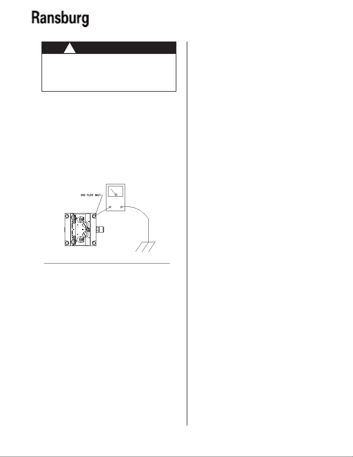
> The color changer MUST be properly grounded. Proper grounding (as described below)
will prevent static charge buildup and possible
discharge from the color changer.
Grounding of the Color Changer
For safety, the color changer MUST be grounded.
Using a 12-gauge wire, ground the output plate
of the color changer to a true earth ground. Using
an ohmmeter, check for ground, testing the earth
ground to the outlet. The resistance should be 10
ohms or less.
NOTES
CS-02-01.10
Figure 2: Grounding the Color Changer
14
MCV 2 Collet Series Color Changer - Installation
INSTALLATION
MCV 2 INSTALLATION
PROCEDURES
Determine Location for Color Changer
The color changer should be located as close as
possible to the spray device in order to save paint
and solvent with a color changer. If possible, use an
enclosure to protect the color changer from airborne
paints and solvents.
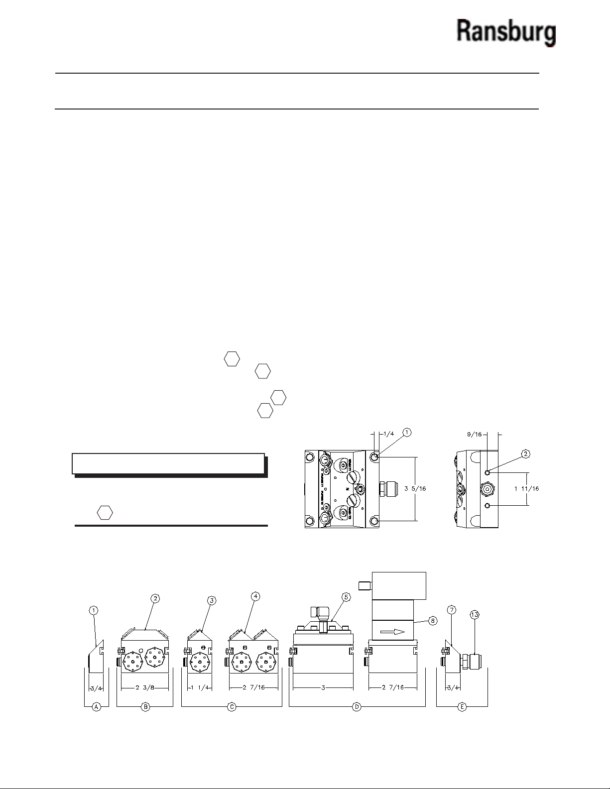
Calculate Footprint of Color Changer
(See Figure 3)
To calculate the footprint of the color changer add:
• The dimension of the end plate
• The dimension of the purge assembly
• The dimension(s) of the module(s) used to
create the desired number of color valves
• The dimension of the output assembly
A
B
C
E
NOTE
Example: To calculate the footprint of an 6-Color
MCV Assembly:
3/4” (End Plate) + 2-3/8” (purge assembly) +
3-11/16” (8-color valve assembly) + 3/4” (output
assembly) = 7-9/16”
Mounting the Color Changer
There are two mounting congurations as follows:
(Reference Figure 4)
1 5/16” clearance holes for ush mounting
to the booth wall.
2 1/4” x 20 threaded holes in the end blocks.
15
> If using the optional control devices (regulator and ow meter) include dimension in
D
calculation above.
Figure 3: Calculate Footprint
Figure 4: Mounting Congurations Footprint
CS-02-01.10

MCV 2 Collet Series Color Changer - Installation
NOTES
CS-02-01.10
16

MCV 2 Collet Series Color Changer - Operation
Solvent
Color 1 IN
Main Air
Flow Meter
Fluid
Regulator
MCV Color Selector
Spray
Device
Color 1 OUT
Color 2 IN
Color 2 OUT
OPERATION
OPERATING
Modules may be added or removed from the assembly as desired; the user need only purchase the
appropriately sized changer. If, for instance, the number of required materials increases, the changer can
be expanded by adding more modules. Also, each
module can be individually serviced. Recommended
for use with waterborne or solventborne paints.
Figure 5a shows “Typical Color Changer Schematics”
to prevent back ow of material. Figure 5b shows
“Typical Bell Wash or Stack Purge Flow Schematics.
Figure 5b: Typical Bell Wash or Stack Purge Flow Sche-
matics
17
Figure 5a: Color Changer Schematics
CS-02-01.10

MCV 2 Collet Series Color Changer - Operation
WASH SOLVENT TRIGGER
(4 mm ODT) (5/32 in ODT)
SOLVENT SUPPLY
(10 mm ODT)
(3/8 in ODT)
WASH AIR TRIGGER
(4 mm ODT)
(5/32 in ODT)
AIR SUPPLY
(10 mm ODT) (3/8 in ODT)
BELL WASH OUTLET
(6mm & 8mm ODT)
(5/16 in ODT)
PURGE SOLVENT TRIGGEER
(4 mm ODT) (5/32 in ODT)
PURGE AIR TRIGGER
(4 mm ODT)
(5/32 in ODT)
COLOR IN
(10 mm ODT)
(3/8 in ODT)
COLOR OUT
(8 mm ODT)
(5/16 in ODT)
OUTLET
(3/8 NPSM (M))
GROUND TO EARTH
GROUND HERE
COLOR TRIGGER
(4 mm ODT)
(5/32 in ODT)
221.54 [8.722 in]
101.40 [3.992 in]
53.95 [2.124 in]
DIMENSIONS METRIC FRACTION & PROPOSED HOOKUP
FOR 8COLORS
CS-02-01.10
18

MCV 2 Collet Series Color Changer - Maintenance
MAINTENANCE
!
> Prior to servicing the unit, ensure that all uid
pressure is relieved to atmosphere. A solvent
purge should be performed if possible.
W A R N I N G
GENERAL MAINTENANCE
NOTE
> When replacing or repairing any components in this system, before reassembling,
apply a light coat of food grade
petroleum jelly to all o-rings.
NOTE
Figure 6: Valve Removal
To remove the seat, insert the seat removal tool
into the seat and turn counter-clockwise using a
3/8” socket, adjustable wrench, or combination box
open-end wrench.
> The following procedure allows valve
and/or seat removal without removing the
valve slice from the assembly.
Value and Seat Removal
To remove the valve for any reason, insert the four
(4) prongs from the tool into the holes on the top the
Microvalve. Using a 1/2” socket, adjustable wrench, or
a combination box open-end wrench, turn counterclockwise to remove the valve.
Figure 7: Seat Removal
19
CS-02-01.10

MCV 2 Collet Series Color Changer - Maintenance
To reinstall, tighten the valve seat rst using the
tool by hand. Then using a torque wrench with a
3/8’ socket, tighten the seat in place, clockwise in
direction to 15 to 20 lbs.•in torque.
NOTE
> Not using a torque wrench for seat installation may cause permanent damage to the
seat pocket of the valve block.
Figure 9: Microvalve Installation
Tube Insertion
Prior to inserting the tube, remove the red clip under
the collet. Insert the tube into the stack collet by
grasping the tube about 2-4-inches from the end.
Press the tube all the way down in the collet until it
cannot be pressed any further, the tube must pass
by both o-rings. Each tube must be inserted into its
mating collet to the proper depth as shown in the
chart below. With the tube inserted, pull the collet
up enough to slide the clip under the collet.
Figure 8: Reinstall Valve and Seat
To install the Microvalve, tighten the valve into the
pocket using the provided tool and a 1/2” wrench
or socket clockwise till the valve has just about
seated. Then using a torque wrench tighten to 1520 lbs.•in.
C A U T I O N
!
> Be careful not to cross thread the parts when
reassembling as this could cause permanent
damage to block.
Tube OD Tube Depth
10mm or 3/8” 3/4” or 19.0mm
8mm or 5/16” 11/16” or 17.5mm
6mm 25/32” or 19.8mm
4mm or 5/32” 5/8” or 16.0mm
CS-02-01.10
20

MCV 2 Collet Series Color Changer - Maintenance
TUBING
Tube Removal
The 4mm trigger line tubes may be removed by hand
by pushing on the collet while pulling out the tube. A
tool is required to remove both the 8mm and 10mm
tubes. To remove the 8mm tube, use the white end of
the tool, and for the 10mm tube use the black end.
First remove the red clips then press the tool against
the collet in the block. With the collet pushed in, pull
out the tube that is being removed (see Figure 10).
REMOVING AND
REINSTALLING A VALVE
BLOCK FROM A STACK
1. Ensure all pressure is bled o the system. If
possible, ush the block with appropriate solvent.
2. Using the clip removal tool (78078-00), push
on the installed locking clip with the “V” cut as
shown in Figure 11.
Figure 10: Tube Removal
!
> Prior to servicing the unit, ensure that all uid
pressure is relieved to atmosphere. A solvent
purge should be performed if possible.
W A R N I N G
Figure 11: 78078-00 Clip Removal Tool
3. Push the locking clips out of the locking slots.
4. Loosen and remove any mounting bolts holding the stack in place.
5. Carefully pull the stack assembly ends apart
and remove the valve block.
!
> Be careful of residual uid pressure or solvent
pressure in the line. Cover the area where the
valve slice is being removed to prevent any
solvent or paint from spraying on you.
6. Replace the valve slice, push the assembly
together and insert the locking clips.
W A R N I N G
21
CS-02-01.10

MCV 2 Collet Series Color Changer - Maintenance
16
3
6
13
2
8
9
4
5
11
7
12
1
15
10
14
Figure 12: Regulator Disassembly/Reassembly Procedure
CS-02-01.10
22

MCV 2 Collet Series Color Changer - Maintenance
REGULATOR DISASSEMBLY /
REASSEMBLY PROCEDURE
Disassembly
1. Remove eight (8) screws [16] using a 5/32” Allen
wrench.
2. Pull cap [14], upper diaphragm [6], and plate
[13] from the assembly.
3. Pull diaphragm assembly [2] from the assembly.
4. Using a 3/16” Allen wrench, remove the regulator insert [8]. By removing the insert, the seat
will be removed [5]. To remove the carbide seat from
the insert, blow compressed air in the hex end of the
insert and the carbide seat will come out.
Figure 13: Diaphragm Assembly Position
NOTE
> The seat and stem are matched sets of
parts, each having a serial number engraved
on them. Care must be taken not to mix nonmatching seats and stems or the regulator
will not perform properly.
Reassembly
1. Install all removed o-rings [9] and [4] on the
insert and the seat. Push the seat [5] into the insert
(straight in) using an arbor press if possible.
2. Insert spring [10], stem [5], and one o-ring [4]
into the regulator body [1].
3. Using a 3/16” Allen wrench, tighten the insert
down until it bottoms out.
5. Add plate [13], upper diaphragm [6], and lid
[14]. Tighten the eight (8) screws [16] in a cross
pattern to 10 lbs•in. Then follow by tightening
each screw in a circular pattern to 20 lbs•in.
4. Locate the dot on the diaphragm assembly [2]
and place it so it is 180° from the outlet hole of
the body.
23
CS-02-01.10

MCV 2 Collet Series Color Changer - Maintenance
TEST AND CHECKOUT
PROCEDURE FOR COLOR
CHANGER
Step 1:
1. Connect air line to a regulated air supply.
2. Attach the air line to a ball valve assembled to
the outlet of the color changer.
3. Adjust the air supply pressure to 100 psi (6.9
bar).
4. Open the ball valve at the outlet of the color
changer.
5. Apply a soap solution on the color changer
manifold.
6. Check the manifold assembly’s mating surfaces between color blocks for soap bubbles.
2. Connect the air supply hose with 100 psi
(6.9 bar) to color inlet valve. Connect a 2-way ball
valve to the matching return port on the color
changer manifold.
3. Turn the ball valve installed on the paint circulation tting to verify recirculation ability.
NOTE
> Ensure valve is closed when completed.
4. Connect the air supply with a 3-way valve
(normally closed) to the color valve cylinder.
5. Activate the 3-way valve to operate the color
valve.
NOTE
NOTE
> If bubbles are observed, dismantle color
changer manifold and repair as required.
7. If no bubbles are present, rinse manifold with
water and blow dry with air.
Step 2:
1. Attach two (2) regulated air supply hoses, one
with a 3-way valve (normally closed) for operating
the color valve cylinder on the color changer. (Set
the pressure to the 3-way valve at 75 psi
(5.8 bar) or more.)
The second hose will be used for supplying 100 psi
(6.9 bar) of air to the color inlet port of each color
changer valve.
> The piston rod on the top of the color valve
assembly should EXTEND and air should
blow out of the color changer outlet. Check
for a crisp and sharp actuation of the color
valve air cylinder.
6. Deactivate the 3-way valve and close the
color valves.
NOTE
> The piston rod on the top of the color
valve assembly should be RETRACTED, and
the air should have stopped blowing out of
the outlet of the color changer.
7. Connect a 1/4-inch (6.4cm) ID hose 3-ft.
(91.4cm) long to the outlet of the color changer.
CS-02-01.10
24

MCV 2 Collet Series Color Changer - Maintenance
EARTH GROUND
(TRUE)
OHMS
10
0
8. Acquire a container of water and ll it with
about 4-inches (10.6cm) of WATER. Position the
hose in the container lled with water.
9. There should be no more than 6 bubbles per
minute coming from the outlet of the hose that is
submerged.
10. If there are more than 6 bubbles per minute,
remove the color valve assembly, replace the
valve seat (77367-00) and reinstall color valve
assembly. If the new seat does not correct the
problem, either the manifold block or color valve
assembly is defective.
11. Proceed to the next color valve and repeat
Steps 2 thru 11.
12. When all the color valves are checked out,
then check the purge valve assembly repeating
Steps 2 thru 11.
!
W A R N I N G
> NEVER wrap the equipment in plastic to
keep it clean. A surface charge may build-up
on the plastic surface and discharge to the
nearest grounded object. Eciency of the
equipment will also be reduced and damage
or failure of the equipment’s components may
occur. WRAPPING THE EQUIPMENT in plastic
will void warranty.
13. Once all valves are operational, deactivate
the 3-way valve, and then disconnect the air
lines used for testing from the color changer.
!
W A R N I N G
> ALWAYS test color changer for conductivity
after assembly or repair. Proper conductivity is
required to assure entire color changer can be
properly grounded when installed.
14. With an ohmmeter, check for conductivity
between the output plate on the color changer
and earth ground. There should be 10 ohms or less
between the two points (see Figure 14).
Figure 14: Ground Test
25
CS-02-01.10

MCV 2 Collet Series Color Changer - Maintenance
NOTES
CS-02-01.10
26

MCV 2 Collet Series Color Changer - Parts Identication
O-RINGS INCLUDED WITH EACH BLOCK ASY.
PARTS IDENTIFICATION
27
Figure 15: A10800 (Metric) & A11077 (English) MCV 2 Color Changer Assemblies
CS-02-01.10

MCV 2 Collet Series Color Changer - Parts Identication
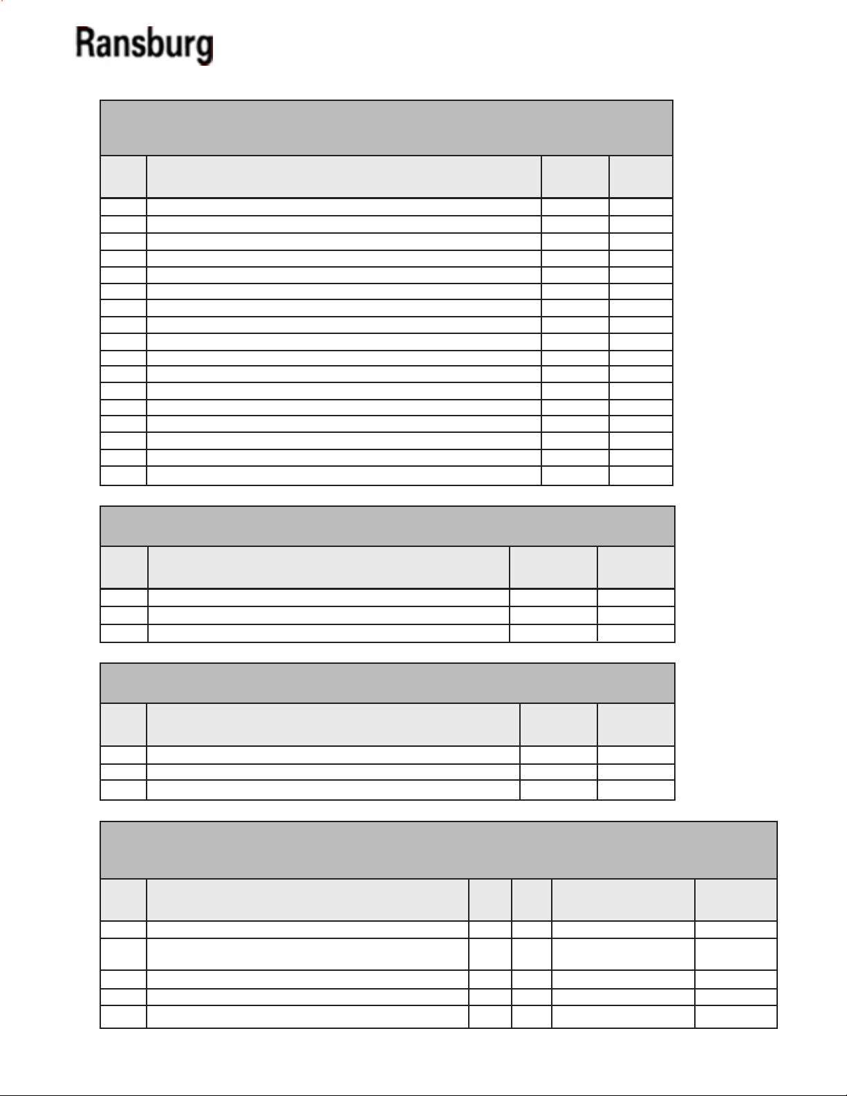
A10800 MCV 2 COLOR CHANGER ASSEMBLY - PARTS LIST (METRIC) (Figure 15)
Item #
1 A10711-00 Assembly, Plate Closed End 1
2 See Table C - “Z” Assembly, Bell/Block Wash (Metric) See Table C - “E”
3 See Table B - “R” Assembly, 2-Color Valve Circulating (Metric) See Table AA - “F”
4 See Table B - “S” Assembly, 4-Color Valve Circulating (Metric) See Table AA - “G”
5 See Table V - “X” Assembly, Regulator See Table V - “T”
6 See Table D - “Y” Assembly, Flow Meter Block See Table D - “H”
7 A10712-00 Assembly, Plate Fitting End 1
8 See Table D - “K” Flow Meter See Table D - “J”
9 78069-00 Fluid Regulator Inlet Tube See Table W - “N”
10 77957-00 Retaining Cup, Color Changer 1
11 A10714-00 Fitting, End 1
12 79001-06 O-Ring, Solvent Proof 2
13 78079-00 Fitting, Outlet 1
14 See Table W - “L” Fluid Regulator See Table W - “M”
15 78098-00 Adapter 1/8” NPT (M) X 3/8” NPS (M) See Table W - “P”
Part # Description
TABLE B - STYLE OF COLOR VALVES (METRIC)
Dash
No.
1
2
3
Description
Circulating (Metric)
Daisy Chain (Metric)
Dead Head (Metric)
“R”
A10727-00
A10726-00
A10733-00
Qty
“S”
A10729-00
A10728-00
A10732-00
TABLE C - BELL / BLOCK WASH OPTION (METRIC)
Dash
No.
CS-02-01.10
Description
0
No Bell / Block Wash
1
W/Both Bell / Block Wash, 8mm Bell Wash
2
W/Block Wash Only, 8mm Bell Wash
3
W/Both Bell / Block Wash, 6mm Bell Wash
4
W/Purge Block Only, 6mm Bell Wash
“E”
0
1
1
1
1
“Z”
0
A10717-02
A10717-01
A11788-02
A11788-01
28

MCV 2 Collet Series Color Changer - Parts Identication
TABLE D - FLOW METER TYPE (METRIC & ENGLISH)
Dash
No.
Description
No Flow Meter
0
Block W/AW Flow Meter Attached -
1
Consult Your Sales Rep. for Pick-Up
Block W/RF-1 Fiber Optic Flow Meter Attached
2
AW Block W/No Flow Meter
3
RF-1 Fiber Optic Block W/No Flow Meter
4
“H”
0
1
1
1
1
TABLE V - INLINE - FLUID REGULATOR OPTION
Dash
No.
Description
No Outlet Regulator
0
DR-2 - 1:1 Ratio
1
DR-2 - 1:2 Ratio
2
DR-2 - 1:3 Ratio
3
DR-2 - 1:4 Ratio
4
DR-2 - 1:6 Ratio
5
DR-2 - 1:8 Ratio
6
DR-2 - 1:10 Ratio
7
“J”
0
1
1
0
0
“K”
0
75955-06
See Table BB - “CC”
0
0
“X”
A10725-01
A10725-02
A10725-03
A10725-04
A10725-06
A10725-06
A10725-08
A10725-10
“Y”
0
A10720-01
A10720-02
A10720-01
A10720-02
“T”
0
1
1
1
1
1
1
1
TABLE W - OUTLET - FLUID REGULATOR RATIO
Dash
No.
Description
No Outlet Regulator
0
DR-1 - 1:1 Ratio
1
DR-1 - 1:2 Ratio
2
DR-1 - 1:3 Ratio
3
DR-1 - 1:4 Ratio
4
DR-1 - 1:6 Ratio
5
DR-1 - 1:8 Ratio
6
DR-1 - 1:10 Ratio
7
“L”
---74151-11
74151-01
74151-06
74151-02
74151-03
74151-04
74151-05
“M”
0
1
1
1
1
1
1
1
“N”
0
1
1
1
1
1
1
1
“P”
0
1
1
1
1
1
1
1
29
CS-02-01.10

MCV 2 Collet Series Color Changer - Parts Identication
TABLE BB - RF 1 FLOW METER KIT / FIBER OPTIC CABLE LENGTH
(METRIC & ENGLISH)
Dash
No.
1
2
3
4
5
6
Description
RF-1 Flow Meter, Receiver & Cable, Fiber Optic Cable
RF-1 Flow Meter, Receiver & Cable, Fiber Optic Cable
RF-1 Flow Meter, Receiver & Cable, Fiber Optic Cable
RF-1 Flow Meter, Receiver & Cable, Fiber Optic Cable
RF-1 Flow Meter, Receiver & Cable, Fiber Optic Cable
RF-1 Flow Meter, Receiver & Cable, Fiber Optic Cable
“CC”
A11516-15
A11516-25
A11516-50
A11516-65
A11516-75
A11516-100
“Fiber Optic Cable
Length”
15 Ft.
25 Ft.
50 Ft.
65 Ft.
75 Ft.
100 Ft.
A11077 MCV 2 COLOR CHANGER ASSEMBLY - PARTS LIST
(ENGLISH) (Figure 15)
Item #
1 A10711-00 Assembly, Plate, Closed End 1
2 See Table C - “Z” Assembly, Bell/Block Wash (Metric) See Table C - “E”
3 See Table B - “R” Assembly, 2-Color Valve (Metric) See Table AA - “F”
4 See Table B - “S” Assembly, 4-Color Valve (Metric) See Table AA - “G”
5 See Table V - “X” Assembly, Regulator See Table V - “T”
6 See Table D - “Y” Assembly, Flow Meter Block See Table D - “H”
7 A10712-00 Assembly, Plate Fitting End 1
8 See Table D - “K” Flow Meter See Table D - “J”
9 78069-00 Fluid Regulator Inlet Tube See Table W - “N”
10 77957-00 Retaining Cup, Color Changer 1
11 A10714-00 Fitting, End 1
12 79001-06 O-Ring, Solvent Proof 2
13 78079-00 Fitting, Outlet 1
14 See Table W - “L” Fluid Regulator See Table W - “M”
15 78098-00 Adapter 1/8” NPT (M) X 3/8 “ NPS (M) See Table W - “P”
Part # Description
Qty
TABLE B - STYLE OF COLOR VALVES (ENGLISH)
Dash
No.
Description
Circulating (English)
1
Daisy Chain (English)
2
Dead Head (English)
3
TABLE C - BELL / BLOCK WASH OPTION - (ENGLISH)
Dash
No.
CS-02-01.10
Description
0
No Bell / Block Wash
1
W/Both Bell / Block Wash
2
W/Block Wash Only
“R”
A10953-00
A10954-00
A10955-00
“E”
0
1
1
“S”
A10960-00
A10961-00
A10962-00
“Z”
0
A11080-02
A11080-01
30

MCV 2 Collet Series Color Changer - Parts Identication
TABLE D - FLOW METER TYPE
Dash
No.
Description
No Flow Meter
0
Block W/AW Flow Meter Attached -
1
Consult Your Sales Rep. for Pick-Up
Block W/RF-1 Fiber Optic Flow Meter Attached
2
AW Block W/No Flow Meter
3
RF-1 Fiber Optic Block W/No Flow Meter
4
“H”
0
1
1
1
1
TABLE V - INLINE - FLUID REGULATOR OPTION
Dash
No.
Description
No Outlet Regulator
0
DR-2 - 1:1 Ratio
1
DR-2 - 1:2 Ratio
2
DR-2 - 1:3 Ratio
3
DR-2 - 1:4 Ratio
4
DR-2 - 1:6 Ratio
5
DR-2 - 1:8 Ratio
6
DR-2 - 1:10 Ratio
7
“J”
0
1
1
0
0
“K”
0
75955-06
See Table BB - “CC”
0
0
“X”
A10725-01
A10725-02
A10725-03
A10725-04
A10725-06
A10725-06
A10725-08
A10725-10
“Y”
0
A10720-01
A10720-02
A10720-01
A10720-02
“T”
0
1
1
1
1
1
1
1
TABLE W - OUTLET - FLUID REGULATOR RATIO
Dash
No.
0
1
2
3
4
5
6
7
Description
No Outlet Regulator
DR-1 - 1:1 Ratio
DR-1 - 1:2 Ratio
DR-1 - 1:3 Ratio
DR-1 - 1:4 Ratio
DR-1 - 1:6 Ratio
DR-1 - 1:8 Ratio
DR-1 - 1:10 Ratio
“L”
---74151-11
74151-01
74151-06
74151-02
74151-03
74151-04
74151-05
“M”
TABLE BB - RF-1 FLOW METER KIT/FIBER OPTIC CABLE LENGTH
(METRIC & ENGLISH)
Dash
No.
100
Description
RF-1 Flow Meter, Receiver & Cable, Fiber Optic Cable
15
RF-1 Flow Meter, Receiver & Cable, Fiber Optic Cable
25
RF-1 Flow Meter, Receiver & Cable, Fiber Optic Cable
35
RF-1 Flow Meter, Receiver & Cable, Fiber Optic Cable
65
RF-1 Flow Meter, Receiver & Cable, Fiber Optic Cable
75
RF-1 Flow Meter, Receiver & Cable, Fiber Optic Cable
“CC”
A11516-15
A11516-25
A11516-50
A11516-65
A11516-75
A11516-100
“N”
0
1
1
1
1
1
1
1
0
1
1
1
1
1
1
1
“P”
0
1
1
1
1
1
1
1
“Fiber Optic Cable
Length”
15 Ft.
25 Ft.
50 Ft.
65 Ft.
75 Ft.
100 Ft.
31
CS-02-01.10

MCV 2 Collet Series Color Changer - Parts Identication
CS-02-01.10
Figure 16: A10717 (Metric) & A11080 (English) Bell/Block Wash Assembly
32

MCV 2 Collet Series Color Changer - Parts Identication
A10717 BELL /BLOCK WASH ASSEMBLY - PARTS LIST
(METRIC) (Figure 16)
Item #
1 78944-00 Assembly, Check Valve 2
2 See Table X - “A” Assembly, Valve Seat or Plug 2
3 See Table X - “B” Assembly, Valve or Plug 2
4 78947-00 Seal 2
5 78945-00 Plug, Check Valve 2
6 77516-04 Collet, 4mm 4
7 A10825-00 Red Locking Clip, 1/4” OD Tube 1
8 79001-30 O-Ring, Solvent Proof 4
9 79001-06 O-Ring, Solvent Proof 3
10 79001-05 O-Ring, Solvent Proof 1
11 79001-34 O-Ring, Solvent Proof 2
12 77762-02 Collet, 10mm 2
13 77762-04 Collet, 8mm 1
14 79001-31 O-Ring, Solvent Proof 4
15 A10824-00 Red Locking Clip, 3/8” OD Tube 2
16 A10968-00 Assembly, Bell Wash & Purge Block (Metric) 1
17 77957-00 Retaining Clip, Color Changer 1
18 77367-00 Assembly, Valve Seat 2
19 78949-00 Assemby, Valve 2
Part # Description
Qty
TABLE X - A10717 BELL / BLOCK WASH ASSEMBLY - PARTS LIST (METRIC)
Part #
A10717-01
A10717-02
Description
Purge Block Only
Bell Wash & Purge Block
“A”
Kit #77620-00
78949-00
“B”
77367-00
33
CS-02-01.10

MCV 2 Collet Series Color Changer - Parts Identication
A11788 BELL /BLOCK WASH ASSEMBLY - PARTS LIST
(METRIC) (Figure 16)
Item #
1 78944-00 Assembly, Check Valve 2
2 See Table X - “A” Assembly, Valve Seat or Plug 2
3 See Table X - “B” Assembly, Valve or Plug 2
4 78947-00 Seal 2
5 78945-00 Plug, Check Valve 2
6 77516-04 Collet, 4mm 4
7 A10825-00 Red Locking Clip, 1/4” OD Tube 1
8 79001-30 O-Ring, Solvent Proof 4
9 79001-06 O-Ring, Solvent Proof 3
10 79001-05 O-Ring, Solvent Proof 1
11 79001-32 O-Ring, Solvent Proof 2
12 77762-02 Collet, 10mm 2
13 77762-01 Collet, 6mm 1
14 79001-31 O-Ring, Solvent Proof 4
15 A10824-00 Red Locking Clip, 3/8” OD Tube 2
16 A10968-00 Assembly, Bell Wash & Purge Block (Metric) 1
17 77957-00 Retaining Clip, Color Changer 1
18 77367-00 Assembly, Valve Seat 2
19 78949-00 Assemby, Valve 2
Part # Description
Qty
TABLE X - A11788 BELL/BLOCK WASH ASSEMBLY - PARTS LIST
Part #
A11788-01
A11788-02
Description
Purge Block Only
Bell Wash & Purge Block
“A”
Kit #77620-00
78949-00
“B”
77367-00
CS-02-01.10
34

MCV 2 Color Changer - Parts Identication
A11080 BELL / BLOCK WASH ASSEMBLY - PARTS LIST
(ENGLISH) (Figure 16)
Item #
1 78944-00 Assembly, Check Valve 2
2 See Table X - “A” Assembly, Valve Seat or Plug 2
3 See Table X - “B” Assembly, Valve or Plug 2
4 78947-00 Seal 2
5 78945-00 Plug, Check Valve 2
6 77516-04 Collet, 5/32” 4
7 A10825-00 Red Locking Clip, 1/4” OD Tube 1
8 79001-30 O-Ring, Solvent Proof 4
9 79001-06 O-Ring, Solvent Proof 3
10 79001-05 O-Ring, Solvent Proof 1
11 79001-34 O-Ring, Solvent Proof 2
12 77762-05 Collet, 3/8” 2
13 77762-04 Collet, 5/16” 1
14 79001-24 O-Ring, Solvent Proof 4
15 A10824-00 Red Locking Clip, 3/8” OD Tube 2
16 A10968-00 Assembly, Bell Wash & Purge Block (Metric) 1
17 77957-00 Retaining Clip, Color Changer 1
18 77367-00 Assembly, Valve Seat 2
19 78949-00 Assemby, Valve 2
Part # Description
TABLE X - A11080 BELL / BLOCK WASH ASSEMBLY PARTS LIST (ENGLISH)
Qty
Part #
A111080-1
A110880-2
Description
Purge Block Only
Bell Wash & Purge Block
“A”
Kit #77620-00
78949-00
“B”
77367-00
35
CS-02-01.10

MCV 2 Collet Series Color Changer - Parts Identication
NOTES
CS-02-01.10
36

MCV 2 Collet Series Color Changer - Parts Identication
8
9
11
1
2
3
12
10
13
7
5
4
6
14
Figure 17: A10727 (Metric) & A10953 (English) 2-Color Valve Circulating Assembly
37
CS-02-01.10

MCV 2 Collet Series Color Changer - Parts Identication
A10727 2-COLOR VALVE CIRCULATING ASSEMBLY PARTS LIST (METRIC) (Figure 17)
Item #
1 A10734-01 Assembly, 2-Color Valve Circulating 1
2 77367-00 Assembly, Valve Seat 2
3 78949-00 Assembly, Valve 2
4 77762-02 Collet, 10mm 2
5 79001-31 O-Ring, Solvent Proof 4
6 77762-04 Collet, 8mm 2
7 79001-34 O-Ring, Solvent Proof 4
8 77516-04 Collet, 4mm 2
9 79001-30 O-Ring, Solvent Proof 2
10 79001-06 O-Ring, Solvent Proof 1
11 76001-05 O-Ring, Solvent Proof 1
12 77957-00 Retaining Clip, Color Changer 1
13 A10824-00 Red Locking Clip, 3/8” OD Tube 2
14 A10825-00 Red Locking Clip, 1/4” OD Tube 2
Part # Description
A10953 2-COLOR VALVE CIRCULATING ASSEMBLY PARTS LIST (ENGLISH) (Figure 17)
Item #
1 A10956-01 Assembly, 2-Color Valve Circulating 1
2 77367-00 Assembly, Valve Seat 2
3 78949-00 Assembly, Valve 2
4 77762-05 Collet, 3/8” 2
5 79001-24 O-Ring, Solvent Proof 4
6 77762-04 Collet, 5/16” 2
7 79001-34 O-Ring, Solvent Proof 4
8 77516-04 Collet, 5/32” 2
9 79001-30 O-Ring, Solvent Proof 2
10 79001-06 O-Ring, Solvent Proof 1
11 76001-05 O-Ring, Solvent Proof 1
12 77957-00 Retaining Clip, Color Changer 1
13 A10824-00 Red Locking Clip, 3/8” OD Tube 2
14 A10825-00 Red Locking Clip, 1/4” OD Tube 2
Part # Description
Qty
Qty
CS-02-01.10
38

MCV 2 Collet Series Color Changer - Parts Identication
3
9
4
5
5
4
8
1
7
6
6
7
2
10
3
9
4
5
5
4
8
1
7
6
6
7
2
10
11
39
Figure 18: A10726 (Metric) & A10954 (English) 2-Color Valve - Daisy Chain
CS-02-01.10

MCV 2 Collet Series Color Changer - Parts Identication
A10726 2-COLOR VALVE - DAISY CHAIN - PARTS LIST
(METRIC) (Figure 18)
Item #
1 A10734-03 Assembly, 2-Color Daisy Chain 1
2 77367-00 Assembly, Valve Seat 2
3 78949-00 Assembly, Valve 2
4 77762-02 Collet, 10mm 4
5 79001-31 O-Ring, Solvent Proof 8
6 77516-04 Collet, 4mm 2
7 79001-30 O-Ring, Solvent Proof 2
8 79001-06 O-Ring, Solvent Proof 1
9 79001-05 O-Ring, Solvent Proof 1
10 77957-00 Retaining Clip, Color Changer 1
11 A10824-00 Red Locking Clip, 3/8” OD Tube 4
Part # Description
A10954 2-COLOR VALVE - DAISY CHAIN - PARTS LIST
(ENGLISH) (Figure 18)
Item #
1 A10956-03 Assembly, 2-Color Daisy Chain 1
2 77367-00 Assembly, Valve Seat 2
3 78949-00 Assembly, Valve 2
4 77762-05 Collet, 3/8” 4
5 79001-24 O-Ring, Solvent Proof 8
6 77516-04 Collet, 5/32” 2
7 79001-30 O-Ring, Solvent Proof 2
8 79001-06 O-Ring, Solvent Proof 1
9 79001-05 O-Ring, Solvent Proof 1
10 77957-00 Retaining Clip, Color Changer 1
11 A10824-00 Red Locking Clip, 3/8” OD Tube 4
Part # Description
Qty
Qty
CS-02-01.10
40

MCV 2 Collet Series Color Changer - Parts Identication
11
8
1
10
3
2
6
7
5
5
4
4
5
5
6
7
2
1
9
3
41
Figure 19: A10733 (Metric) & A10955 (English) 2-Color Valve - Dead Head
CS-02-01.10

MCV 2 Collet Series Color Changer - Parts Identication
A10733 2-COLOR VALVE - DEAD HEAD - PARTS LIST
(METRIC) (Figure 19)
Item #
1 A10734-02 Assembly, 2-Color Dead Head (Metric) 1
2 77367-00 Assembly, Valve Seat 2
3 78949-00 Assembly, Valve 2
4 77762-02 Collet, 10mm 2
5 79001-31 O-Ring, Solvent Proof 4
6 77516-04 Collet, 4mm 2
7 79001-30 O-Ring, Solvent Proof 2
8 79001-06 O-Ring, Solvent Proof 1
9 79001-05 O-Ring, Solvent Proof 1
10 77957-00 Retaining Clip, Color Changer 1
11 A10824-00 Red Locking Clip, 3/8” OD Tube 2
Part # Description
A10955 2-COLOR VALVE - DEAD HEAD - PARTS LIST
(ENGLISH) (Figure 19)
Item #
1 A10956-02 Assembly, 2-Color Dead Head (Metric) 1
2 77367-00 Assembly, Valve Seat 2
3 78949-00 Assembly, Valve 2
4 77762-05 Collet, 3/8” 2
5 79001-24 O-Ring, Solvent Proof 4
6 77516-04 Collet, 5/32” 2
7 79001-30 O-Ring, Solvent Proof 2
8 79001-06 O-Ring, Solvent Proof 1
9 79001-05 O-Ring, Solvent Proof 1
10 77957-00 Retaining Clip, Color Changer 1
11 A10824-00 Red Locking Clip, 3/8” OD Tube 2
Part # Description
Qty
Qty
CS-02-01.10
42

MCV 2 Collet Series Color Changer - Parts Identication
43
Figure 20: A10729 (Metric) & A10960 (English) 4-Color Valve Circulating Assembly
CS-02-01.10

MCV 2 Collet Series Color Changer - Parts Identication
A10729 4-COLOR VALVE CIRCULATING ASSEMBLY PARTS LIST (METRIC) (Figure 20)
Item #
1 A10735-01 Assembly, Circulating 4-Color Stack 1
2 77367-00 Assembly, Valve Seat 4
3 78949-00 Assembly, Valve 4
4 77762-02 Collet, 10mm 4
5 79001-31 O-Ring, Solvent Proof 8
6 77762-04 Collet, 8mm 4
7 79001-34 O-Ring, Solvent Proof 8
8 77516-04 Collet, 4mm 4
9 79001-30 O-Ring, Solvent Proof 4
10 79001-06 O-Ring, Solvent Proof 1
11 79001-05 O-Ring, Solvent Proof 1
12 77957-00 Retaining Clip, Color Changer 1
13 A10824-00 Red Locking Clip, 3/8” OD Tube 4
14 A10825-00 Red Locking Clip, 1/4” OD Tube 4
Part # Description
A10960 4-COLOR VALVE CIRCULATING ASSEMBLY PARTS LIST (ENGLISH) (Figure 20)
Item #
1 A10960-00 Assembly, Circulating 4-Color Stack 1
2 77367-00 Assembly, Valve Seat 4
3 78949-00 Assembly, Valve 4
4 77762-05 Collet, 3/8” 4
5 79001-24 O-Ring, Solvent Proof 8
6 77762-04 Collet, 5/16” 4
7 79001-24 O-Ring, Solvent Proof 8
8 77516-04 Collet, 5/32” 4
9 79001-30 O-Ring, Solvent Proof 4
10 79001-06 O-Ring, Solvent Proof 1
11 79001-05 O-Ring, Solvent Proof 1
12 77957-00 Retaining Clip, Color Changer 1
13 A10824-00 Red Locking Clip, 3/8” OD Tube 4
14 A10825-00 Red Locking Clip, 1/4” OD Tube 4
Part # Description
Qty
Qty
CS-02-01.10
44

MCV 2 Collet Series Color Changer - Parts Identication
8
5
4
6
3
2
1
10
9
7
11
45
Figure 21: A10728 (Metric) & A10961 (English) 4-Color Valve - Daisy Chain Assembly
CS-02-01.10

MCV 2 Collet Series Color Changer - Parts Identication
A10728 4-COLOR VALVE - DAISY CHAIN ASSEMBLY PARTS LIST (METRIC) (Figure 21)
Item #
1 A10735-03 Assembly, Body 4-Color - Daisy Chain 1
2 77367-00 Assembly, Valve Seat 4
3 78949-00 Assembly, Valve 4
4 77762-02 Collet, 10mm 8
5 79001-31 O-Ring, Solvent Proof 16
6 77516-04 Collet, 4mm 4
7 79001-30 O-Ring, Solvent Proof 4
8 79001-06 O-Ring, Solvent Proof 1
9 79001-05 O-Ring, Solvent Proof 1
10 77957-00 Retaining Clip, Color Changer 1
11 A10824-00 Red Locking Clip, 3/8” OD Tube 8
Part # Description
A10961 4-COLOR VALVE - DAISY CHAIN ASSEMBLY PARTS LIST (ENGLISH) (Figure 21)
Item #
1 A10963-03 Assembly, Body 4-Color - Daisy Chain 1
2 77367-00 Assembly, Valve Seat 4
3 78949-00 Assembly, Valve 4
4 77762-05 Collet, 3/8” 8
5 79001-24 O-Ring, Solvent Proof 16
6 77516-04 Collet, 5/32” 4
7 79001-30 O-Ring, Solvent Proof 4
8 79001-06 O-Ring, Solvent Proof 1
9 79001-05 O-Ring, Solvent Proof 1
10 77957-00 Retaining Clip, Color Changer 1
11 A10824-00 Red Locking Clip, 3/8” OD Tube 8
Part # Description
Qty
Qty
CS-02-01.10
46

MCV 2 Collet Series Color Changer - Parts Identication
3
2
9
1
8
7
6
5
5
4
11
10
47
Figure 22: A10732 (Metric) & A10962 (English) 4-Color Valve Dead Head Assembly
CS-02-01.10

MCV 2 Collet Series Color Changer - Parts Identication
A10732 4-COLOR VALVE DEAD HEAD ASSEMBLY PARTS LIST (METRIC) (Figure 22)
Item #
1 A10735-02 Assembly, Block 4-Color Dead Head 1
2 77367-00 Assembly, Valve Seat 4
3 78949-00 Assembly, Valve 4
4 77762-02 Collet, 10mm 4
5 79001-31 O-Ring, Solvent Proof 8
6 77516-04 Collet, 4mm 4
7 79001-30 O-Ring, Solvent Proof 4
8 79001-06 O-Ring, Solvent Proof 1
9 79001-05 O-Ring, Solvent Proof 1
10 77957-00 Retaining Clip, Color Changer 1
11 A10824-00 Red Locking Clip, 3/8” OD Tube 4
Part # Description
A10962 4-COLOR VALVE DEAD HEAD ASSEMBLY PARTS LIST (ENGLISH) (Figure 22)
Item #
1 A10963-02 Assembly, Block 4-Color Dead Head 1
2 77367-00 Assembly, Valve Seat 4
3 78949-00 Assembly, Valve 4
4 77762-05 Collet, 3/8” 4
5 79001-24 O-Ring, Solvent Proof 8
6 77516-04 Collet, 5/32” 4
7 79001-30 O-Ring, Solvent Proof 4
8 79001-06 O-Ring, Solvent Proof 1
9 79001-05 O-Ring, Solvent Proof 1
10 77957-00 Retaining Clip, Color Changer 1
11 A10824-00 Red Locking Clip, 3/8” OD Tube 4
Part # Description
Qty
Qty
CS-02-01.10
48

MCV 2 Collet Series Color Changer - Parts Identication
16
3
6
13
2
8
9
4
5
11
7
12
1
15
10
14
Figure 23: A10725 Regulator Assembly
49
CS-02-01.10

MCV 2 Collet Series Color Changer - Parts Identication
A10725 REGULATOR ASSEMBLY - PARTS LIST (Figure 23)
Item #
1 A10724-00 Assembly, Regulator Body 1
2 See Table A - “A” Assembly, Diaphragm DR-2 1
3 A11069-00 Fitting, Elbow, Push-In, 1/8” NPT X 4mm (5/32”) ODT 1
4 79001-08 O-Ring, Solvent Proof 2
5 74160-00 Assembly Matched Seat & Stem 1
6 74157-03 Diaphragm, Regulator 1
7 79001-05 O-Ring, Solvent Proof 1
8 79238-00 Insert, Regulator 1
9 79001-18 O-Ring, Solvent Proof 1
10 74161-00 Spring, Regulator 1
11 79001-06 O-Ring, Solvent Proof 1
12 77957-00 Retaining Clip, Color Changer 1
13 See Table A - “B” Ratio Spacer Ring, Fluid Regulator 1
14 79231-00 Cap, Fluid Regulator 1
15 77544-01 Fitting, Straight, Push-In, 1/8” NPT X 4mm (5/32”) ODT 2
16 LSFA-0006-40F Screw, Socket Head Cap, 10-32 X 1-1/4” Lg. 8
Part # Description
TABLE A - A10725 REGULATOR ASSEMBLY
Dash
No.
01
02
03
04
06
08
10
Description
Regulator Ratio 1:1
Regulator Ratio 1:2
Regulator Ratio 1:3
Regulator Ratio 1:4
Regulator Ratio 1:6
Regulator Ratio 1:8
Regulator Ratio 1:10
“A”
79235-01
79235-02
79235-03
79235-04
79235-06
79235-08
79235-10
A11067-01
A11067-02
A11067-03
A11067-04
A11067-06
A11067-08
A11067-10
Qty
“B”
CS-02-01.10
50

MCV 2 Collet Series Color Changer - Parts Identication
7
4
3
3
4
3
3
3
1
6
5
Figure 24: A10720-01/02 Flow Meter Block Assembly
A10720-01/02 FLOW METER BLOCK ASSEMBLY - PARTS LIST
(Figure 24)
Item #
1 A10719-00 Assembly, Flow Meter Block 1
2 A10467-00 Assembly, Flow Meter Plate 1
3 79001-05 O-Ring, Solvent Proof 5
4 78232-16C Screw, Counter Sunk Head 6
5 79001-06 O-Ring, Solvent Proof 1
6 77957-00 Retaining Clip, Color Changer 1
7 See Table Y - “A” Screw, SHC 4
TABLE Y - FLOW METER BLOCK ASSEMBLY OPTION
Part #
A10720-01
A10720-02
Part # Description
Description
AW Flow Meter Block
RF-1 Fiber Optic Flow Meter Block
Qty
“A”
A10468-45
A10468-50
51
CS-02-01.10

MCV 2 Collet Series Color Changer - Parts Identication
Figure 25: A10826-XX Stand Alone Bell/Block Wash Assembly
A10826-XX STAND ALONE BELL / BLOCK WASH ASSEMBLY PARTS LIST (METRIC & ENGLISH) (Figure 25)
Item #
1 A10711-00 Assembly, Plate Closed End 1
2 See Table Z - “A” Assembly, Bell / Block Wash (Metric) 1
3 77957-00 Retaining Clip, Color Changer 1
4 79001-06 O-Ring, Solvent Proof 2
5 A10714-00 Fitting, End 1
6 A10712-00 Assembly, Plate Fitting, End 1
7 78079-00 Fitting, Outlet 1
Part # Description
TABLE Z - A10826 STAND ALONE BELL / BLOCK WASH ASSEMBLY
OPTIONS
Part #
A10826-01
A10826-02
A10826-03
A10826-04
A10826-06
A10826-06
Description
Purge Block Only, 8mm (Metric)
Bell Wash & Purge Block, 8mm (Metric)
Purge Block Only (English)
Bell Wash & Purge Block (English)
Purge Block Only, 6mm (Metric)
Bell Wash Purge Block, 6mm (Metric)
A10717-01
A10717-02
A10080-01
A11080-02
A11788-01
A11788-02
Qty
“A”
CS-02-01.10
52

MCV 2 Collet Series Color Changer - Parts Identication
Figure 26: A10827-00 Stand Alone Regulator Assembly
A10827-00 STAND ALONE REGULATOR ASSEMBLY PARTS LIST (Figure 26)
Item #
1 79001-05 O-Ring, Solvent Proof 1
2 See Table A Assembly, Regulator 1
3 77957-00 Retaining Clip, Color Changer 1
4 79001-06 O-Ring, Solvent Proof 2
5 A10714-00 Fitting, End 1
6 A10712-00 Assembly, Plate Fitting End 2
7 78079-00 Fitting, Outlet 2
Part # Description
TABLE A - A10827-00 REGULATOR ASSEMBLY
Part #
A10827-01
A10827-02
A10827-03
A10827-04
A10827-06
A10827-08
A10827-10
Description
Regulator- 1:1 Ratio
Regulator - 1:2 Ratio
Regulator - 1:3 Ratio
Regulator - 1:4 Ratio
Regulator - 1:6 Ratio
Regulator - 1:8 Ratio
Regulator - 1:10 Ratio
A10725-01
A10725-02
A10725-03
A10725-04
A10725-06
A10725-08
A10725-10
Qty
“A”
53
CS-02-01.10

MCV 2 Collet Series Color Changer - Parts Identication
Figure 27: A10828-XX Stand Alone Flow Meter Assembly (RF-1 Fiber Optic)
A10828-XX STAND ALONE FLOW METER ASSEMBLY
(RF-1 FIBER OPTIC) - PARTS LIST (Figure 27)
Item #
1 79001-05 O-Ring, Solvent Proof 1
2 See Table BB - “CC” Flow Meter and Cable 1
3 77957-00 Retaining Clip, Color Changer 1
4 79001-06 O-Ring, Solvent Proof 2
5 A10714-00 Fitting, End 1
6 A10712-00 Assembly Plate, Fitting End 2
7 78079-00 Fitting, Outlet 2
8 A10720-02 Assembly Flow Meter Block 1
Part # Description
TABLE BB - RF -1 FLOW METER KIT/ FIBER OPTIC CABLE LENGTH
(METRIC & ENGLISH)
Dash
No.
15
25
50
65
75
100
Description
RF-1 Flow Meter, Receiver & Cable, Fiber Optic Cable
RF-1 Flow Meter, Receiver & Cable, Fiber Optic Cable
RF-1 Flow Meter, Receiver & Cable, Fiber Optic Cable
RF-1 Flow Meter, Receiver & Cable, Fiber Optic Cable
RF-1 Flow Meter, Receiver & Cable, Fiber Optic Cable
RF-1 Flow Meter, Receiver & Cable, Fiber Optic Cable
“CC”
A11516-15
A11516-25
A11516-50
A11516-65
A11516-75
A11516-100
“Fiber Optic Cable
Length”
15 Ft.
25 Ft.
50 Ft.
65 Ft.
75 Ft.
100 Ft.
Qty
CS-02-01.10
54

MCV 2 Collet Series Color Changer - Parts Identication
Figure 28: A10999-00 Stand Alone Flow Meter Assembly (AW)
A10999-00 STAND ALONE FLOW METER ASSEMBLY (AW) PARTS LIST (Figure 28)
Item #
1 79001-05 O-Ring, Solvent Proof 1
2 75955-06 Flow Meter, AW (Consult Your Sales Rep. for 1
Pick-Up)
3 77957-00 Retaining Clip, Color Changer 1
4 79001-06 O-Ring, Solvent Proof 2
5 A10714-00 Fitting, End 1
6 A10712-00 Assembly, Plate Fitting End 2
7 78079-00 Fitting, Outlet 2
8 A10720-01 Assembly, Flow Meter Block, AW 1
Part # Description
Qty
55
CS-02-01.10

MCV 2 Collet Series Color Changer - Parts Identication
3
2
1
2
Figure 29a: 78949-00 Valve & 77367-00 Seat Replacement Parts
78949-00 VALVE & 77367-00 SEAT REPLACEMENT
PARTS (Figure 29a)
Item #
1 79244-00 Plug 1
2 79001-19 O-Ring, Solvent Proof 1
3 79001-14 O-Ring, Solvent Proof 1
4 77618-00 Plug, Seat 1
Part # Description
Figure 29b: 77620-00 Valve Plug Kit
77620-00 VALVE PLUG KIT (Use in Place of Valve & Seat)
(Optional) (Figure 29b)
Item #
1 79244-00 Plug 1
2 79001-19 O-Ring, Solvent Proof 1
3 79001-14 O-Ring, Solvent Proof 1
4 77618-00 Plug, Seat 1
Part # Description
Qty
Qty
CS-02-01.10
56

MCV 2 Collet Series Color Changer - Parts Identication
RECOMMENDED SPARE PARTS
Part #
74160-00
74161-00
77957-00
A10824-00
A10825-00
79001-05
79001-06
Description
Needle and Seat, Regulating
Spring
Retaining Clip
Locking Clip, 3/18”
Locking Clip, 1/4”
O-Ring, Solvent Proof
O-Ring, Solvent Proof
57
CS-02-01.10

MCV 2 Collet Series Color Changer - Parts Identication
NOTES
CS-02-01.10
58

MCV 2 Collet Series Color Changer - Warranty Policies
WARRANTY POLICIES
LIMITED WARRANTY
Ransburg will replace or repair without charge any
part and/or equipment that fails within the specied
time (see below) because of faulty workmanship or
material, provided that the equipment has been used
and maintained in accordance with Ransburg’s written safety and operating instructions, and has been
used under normal operating conditions. Normal
wear items are excluded.
THE USE OF OTHER THAN RANSBURG APPROVED
PARTS VOIDS ALL WARRANTIES.
SPARE PARTS: One hundred and eighty (180) days
from date of purchase, except for rebuilt parts (any
part number ending in “R”) for which the warranty
period is ninety (90) days.
EQUIPMENT: When purchased as a complete unit,
(examples: guns, power supplies, control units, etc.),
is one (1) year from date of purchase. WRAPPING THE
APPLICATOR, ASSOCIATED VALVES AND TUBING,
AND SUPPORTING HARDWARE IN PLASTIC, SHRINK
WRAP, OR ANY OTHR NONAPPROVED COVERING,
WILL VOID THIS WARRANTY.
RANTY IS TO REPLACE PARTS THAT HAVE FAILED BE
CAUSE OF FAULTY WORKMANSHIP OR MATERIALS.
THERE ARE NO IMPLIED WARRANTIES NOR WAR
RANTIES OF EITHER MERCHANTABILITY OR FITNESS
FOR A PARTICULAR PURPOSE. RANSBURG ASSUMES
NO LIABILITY FOR INJURY, DAMAGE TO PROPERTY
OR FOR CONSEQUENTIAL DAMAGES FOR LOSS OF
GOODWILL OR PRODUCTION OR INCOME, WHICH
RESULT FROM USE OR MISUSE OF THE EQUIPMENT
BY PURCHASER OR OTHERS.
EXCLUSIONS:
If, in Ransburg’s opinion the warranty item in question, or other items damaged by this part was improperly installed, operated or maintained, Ransburg
will assume no responsibility for repair or replacement of the item or items. The purchaser, therefore
will assume all responsibility for any cost of repair or
replacement and service related costs if applicable.
RANSBURG’S ONLY OBLIGATION UNDER THIS WAR
59 CS-02-01.10

MANUAL CHANGE SUMMARY
This manual was published to replace Service Manual CS-02-01.9, MCV 2 Collet Series Modular Color Changer
to make the following changes:
1. Change logo.

Service Manual Price: $30.00 (U.S.)
Manufacturing
1910 North Wayne Street
Angola, Indiana 46703-9100
Telephone: 260/665-8800
Fax: 260/665-8516
Technical/Service Assistance
Automotive Assembly and Tier I Telephone: 800/ 626-3565 Fax: 419/ 470-2040
Industrial Systems Telephone: 800/ 233-3366 Fax: 419/ 470-2071
Ransburg Guns Telephone: 800/ 233-3366 Fax: 419/ 470-2071
www.ransburg.com
Technical Support Representative will direct you to the appropriate telephone number for ordering
Spare Parts.
© 2013 Ransburg. All rights reserved.
Models and specications subject to change without notice.
Form No. CS-02-01.10
Litho in U.S.A.
01/13
 Loading...