

SERVICE MANUAL
CP-13-07.2
MAY - 2013
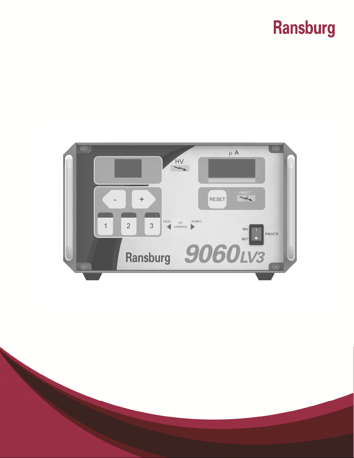
9060 CASCADE LOW VOLTAGE
CONTROLLER
(LV3 - Handguns)
MODEL: 80131-XXX
IMPORTANT: Before using this equipment, carefully read
SAFETY PRECAUTIONS, starting on page 1, and all instructions
in this manual. Keep this Service Manual for future reference.
Service Manual Price: $50.00 (U.S.)
Service Manual Price: $50.00 (U.S.)
Service Manual Price: $50.00 (U.S.)Service Manual Price: $50.00 (U.S.)

CP-13-07.2

9060 Cascade Low Voltage Controller - Contents
CONTENTS
SAFETY:
SAFETY PRECAUTIONS ......................................................................................................... 1
HAZARDS / SAFEGUARDS................................................................................................... 2-5
INTRODUCTION:
7-12
PAGE
1-6
GENERAL DESCRIPTION ........................................................................................................ 7
SAFETY FEATURES ................................................................................................................ 7
DISPLAYS ................................................................................................................................ 7
SPECIFICATIONS .................................................................................................................... 8
CONTROLLER FEATURES ...................................................................................................... 9
OPERATOR INTERFACE ....................................................................................................... 10
SWITCHES ............................................................................................................................. 10
LEDS ...................................................................................................................................... 10
BUTTONS .......................................................................................................................... 10-11
CONNECTION INTERFACE ................................................................................................... 11
CONNECTORS....................................................................................................................... 11
FUSES .................................................................................................................................... 12
SIGNAL INTERFACE ............................................................................................................. 12
INSTALLATION: 13-20
GENERAL INFORMATION ..................................................................................................... 13
LOCATION OF THE 9060 ....................................................................................................... 13
ELECTRICAL NOISE .............................................................................................................. 14
I/O CONNECTIONS ................................................................................................................ 15
AC INPUT CONNECTIONS ............................................................................................... 15-16
SAFETY GROUND ................................................................................................................. 17
INPUT VOLTAGE SELECTION .............................................................................................. 17
INTERLOCKS .................................................................................................................... 17-19
LOW VOLTAGE CABLE ......................................................................................................... 19
RELAY CONTACT OUTPUTS ................................................................................................ 19
HANDGUN TRIGGER SIGNAL ............................................................................................... 20
OPERATION: 21-26
START-UP .............................................................................................................................. 21
BASIC OPERATIONS ........................................................................................................ 21-22
LOCKOUTS ....................................................................................................................... 22-23
KV TEST JUMPER ................................................................................................................. 23
SETPOINT OPERATIONS ...................................................................................................... 24
FAULT DESCRIPTIONS .................................................................................................... 24-26
CP-13-07.2
9060 Cascade Low Voltage Controller - Contents
CONTENTS
MAINTENANCE: 27-30
TROUBLESHOOTING GUIDE ................................................................................................ 27
FAULT TROUBLESHOOTING GUIDE ............................................................................... 27-29
PARTS IDENTIFICATION: 31-32
LOW VOLTAGE CONTROLLER MODEL IDENTIFICATION .................................................. 31
PARTS LIST ........................................................................................................................... 32
ACCESSORIES: 33-34
ACCESSORIES LIST .............................................................................................................. 33
WARRANTY POLICIES: 35
LIMITED WARRANTY ............................................................................................................ 35
PAGE
CP-13-07.2

CP-13-07.2
9060 Cascade Low Voltage Controller - Safety
SAFETY
SAFETY PRECAUTIONS
Before operating, maintaining or servicing any
Ransburg electrostatic coating system, read
and understand all of the technical and safety
literature for your Ransburg products. This
manual contains information that is important
for you to know and understand. This information relates to USER SAFETY and PREVENTING EQUIPMENT PROBLEMS. To help
you recognize this information, we use the following symbols. Please pay particular attention
to these sections.
A WARNING! states information to alert you
to a situation that might cause serious injury if instructions are not followed.
A CAUTION! states information that tells
how to prevent damage to equipment or
how to avoid a situation that might cause
minor injury.
A NOTE is information relevant to the procedure in progress.
While this manual lists standard specifications
and service procedures, some minor deviations may be found between this literature and
your equipment. Differences in local codes and
plant requirements, material delivery requirements, etc., make such variations inevitable.
Compare this manual with your system installation drawings and appropriate Ransburg
equipment manuals to reconcile such differences.
The user MUST read and be familiar
with the Safety Section in this manual and
the Ransburg safety literature therein
identified.
This manual MUST be read and thor-
oughly understood by ALL personnel who
operate, clean or maintain this equipment!
Special care should be taken to ensure that
the WARNINGS and safety requirements
for operating and servicing the equipment
are followed. The user should be aware of
and adhere to ALL local building and fire
codes and ordinances as well as NFPA-33
SAFETY STANDARD, prior to installing,
operating, and/or servicing this equipment.
The hazards shown on the following
page may occur during the normal use of
this equipment. Please read the hazard
chart beginning on page 2.
W A R N I N G
!
W A R N I N G
!
Careful study and continued use of this manual
will provide a better understanding of the
equipment and process, resulting in more efficient operation, longer trouble-free service and
faster, easier troubleshooting. If you do not
have the manuals and safety literature for your
Ransburg system, contact your local
Ransburg representative or Ransburg.
1 CP-13-07.2
9060 Cascade Low Voltage Controller - Safety
AREA
Tells where hazards
may occur.
Spray Area
HAZARD
Tells what the hazard is.
Fire Hazard
Improper or inadequate operation and maintenance procedures will cause a fire hazard.
Protection against inadvertent
arcing that is capable of causing
fire or explosion is lost if any
safety interlocks are disabled
during operation. Frequent Controller shutdown indicates a
problem in the system requiring
correction.
SAFEGUARDS
Tells how to avoid the hazard.
Fire extinguishing equipment must be present in
the spray area and tested periodically.
Spray areas must be kept clean to prevent the
accumulation of combustible residues.
Smoking must never be allowed in the spray
area.
The high voltage supplied to the atomizer must
be turned off prior to cleaning, flushing or
maintenance.
When using solvents for cleaning:
Those used for equipment flushing should have
flash points equal to or higher than those of the
coating material.
Those solvents used for cleaning must have a
flash point at minimum of 5°C (9°F) greater than
ambient temperature. It is the end users responsibility to ensure this condition is met.
Spray booth ventilation must be kept at the rates
required by NFPA-33, OSHA, and local codes.
In addition, ventilation must be maintained
during cleaning operations using flammable or
combustible solvents.
Electrostatic arcing must be prevented.
Test only in areas free of combustible material.
Testing may require high voltage to be on, but
only as instructed.
Non-factory replacement parts or unauthorized equipment modifications may cause fire or
injury.
If used, the key switch bypass is intended for
use only during setup operations. Production
should never be done with safety interlocks disabled.
Never use equipment intended for use in waterborne installations to spray solvent based materials.
The paint process and equipment should be set
up and operated in accordance with NFPA-33,
NEC, and European Health and Safety Norms.
CP-13-07.2 2
9060 Cascade Low Voltage Controller - Safety
AREA
Tells where hazards
may occur.
Spray Area
HAZARD
Tells what the hazard is.
Fire and/or explosion.
SAFEGUARDS
Tells how to avoid the hazard.
Electrostatic arcing MUST be prevented.
The 78789 control panel, LEPS5001 power supply and all other electrical equipment must be
located outside Class I or II, Division 1 or 2 hazardous areas, in accordance with NFPA-33.
Test only in areas free of flammable or combustible materials.
The current overload sensitivity MUST be set as
described in the OVERLOAD ADJUSTMENT
Procedures section of this manual. Protection
against inadvertent arcing that is capable
of causing fire or explosion is lost if the current overload sensitivity is not properly
set. Frequent power supply shutdown indicates
a problem in the system which requires correction.
Always turn the control panel off prior to flushing, cleaning, or working on spray system equipment.
General Use and
Maintenance
Improper operation or maintenance may create a hazard.
Personnel must be properly
trained in the use of this equipment.
Ensure that the control panel is interlocked with
the ventilation system and conveyor in accordance with NFPA-33, EN 50176.
Have fire extinguishing equipment readily available and tested periodically.
Personnel must be given training in accordance
with the requirements of NFPA-33, EN 60079-0.
Instructions and safety precautions must be
read and understood prior to using this equipment.
Comply with appropriate local, state, and national codes governing ventilation, fire protection,
operation maintenance, and housekeeping. Reference OSHA, NFPA-33, EN Norms and your
insurance company requirements.
3 CP-13-07.2
9060 Cascade Low Voltage Controller - Safety
AREA
Tells where hazards
may occur.
Electrical
Equipment
HAZARD
Tells what the hazard is.
High voltage equipment is utilized.
Arcing in areas of flammable or
combustible materials may occur.
Personnel are exposed to high
voltage during operation and
maintenance.
Protection against inadvertent arcing that may cause a fire or explosion is lost if safety circuits are disabled during operation.
Frequent power supply shut-down
indicates a problem in the system
which requires correction.
An electrical arc can ignite coating
materials and cause a fire or explosion.
SAFEGUARDS
Tells how to avoid the hazard.
The power supply, optional remote control
cabinet, and all other electrical equipment
must be located outside Class I or II, Division
1 and 2 hazardous areas. Refer to NFPA-33
or EN 50176.
Turn the power supply OFF before working on
the equipment.
Test only in areas free of flammable or combustible material.
Testing may require high voltage to be on, but
only as instructed.
Production should never be done with the
safety circuits disabled.
Before turning the high voltage on, make sure
no objects are within the sparking distance.
Toxic Substances
Certain material may be harmful if
inhaled, or if there is contact with
the skin.
Follow the requirements of the Material Safety Data Sheet supplied by coating material
manufacturer.
Adequate exhaust must be provided to keep
the air free of accumulations of toxic materials.
Use a mask or respirator whenever there is a
chance of inhaling sprayed materials. The
mask must be compatible with the material
being sprayed and its concentration. Equipment must be as prescribed by an industrial
hygienist or safety expert, and be NIOSH approved.
CP-13-07.2 4
9060 Cascade Low Voltage Controller - Safety
AREA
Tells where hazards
may occur.
Spray Area /
High Voltage
Equipment
HAZARD
Tells what the hazard is.
There is a high voltage
device that can induce an
electrical charge on ungrounded objects which
is capable of igniting coating materials.
Inadequate grounding will
cause a spark hazard. A
spark can ignite many
coating materials and
cause a fire or explosion.
SAFEGUARDS
Tells how to avoid the hazard.
Parts being sprayed must be supported on conveyors
or hangers and be grounded. The resistance between
the part and ground must not exceed 1 megaohm.
(Reference NFPA-33 or EN 50176)
All electrically conductive objects in the spray area,
with the exception of those objects required by the
process to be at high voltage, must be grounded.
Any person working in the spray area must be
grounded.
Unless specifically approved for use in hazardous locations, the power supply and other electrical control
equipment must not be used in Class 1, Division 1 or
2 locations or Class 1, Zone 0 for European Applications.
5 CP-13-07.2

9060 Cascade Low Voltage Controller - Safety
N O T E S
CP-13-07.2 6
9060 Cascade Low Voltage Controller - Introduction
INTRODUCTION
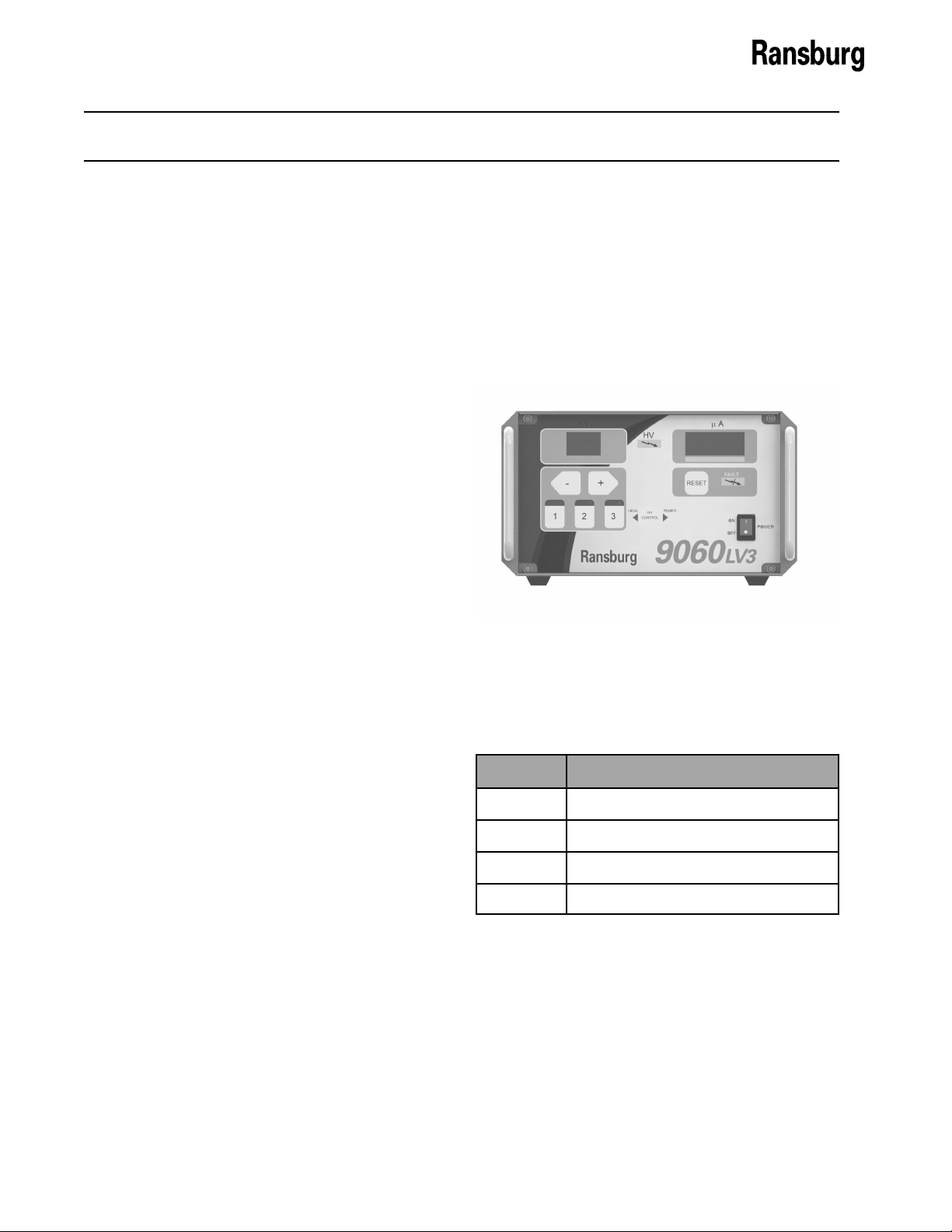
GENERAL DESCRIPTION
The Ransburg 9060 Cascade Low Voltage
Controller (80131-XXX) is used to provide
high voltage for electrostatic application
equipment. It uses a combination of proven
high voltage generation technology and
microprocessor-based control. It uses a
variable voltage output to drive an external
cascade that amplifies the voltage to a high
kV level. It also uses current feedback
information to maintain the desired set point.
The processor circuitry provides the maximum
in applicator transfer efficiency, while maintaining the maximum safety.
The 9060 Controller provides the selection
and adjustment of set point values is performed from the controller front panel. The
trigger of the HV is initiated by the airflow
switch built into the controller which senses
airflow triggered by a standard handgun.
DISPLAYS
The front panel displays the high voltage set
point as well as a reading of gun current output. The gun current is derived from feedback signals in the low voltage cable between the controller and the cascade.
Figure 1: 9060 Cascade Low Voltage Controller
SAFETY FEATURES
When used with the appropriate applicators
and cascades, the Ransburg 9060 Cascade
Low Voltage Controller provides maximized
operational safety. The protections include
detection of Ground Faults, Cable Faults,
Feedback Signal Faults, Overvoltage, and
Overcurrent. The microprocessor circuits
provide a controlled output load curve, which
limits the high voltage output to safe levels
while monitoring control and feedback signals
for unsafe conditions. Maximum operational
safety is obtained when the correct applicator
settings are used and when safe distances
between the applicator and target are observed and followed. The maximum efficiency
of the low voltage controller is based on load.
The 9060 Low Voltage Controller (80131XXX) is available as follows:
Part #: Description
80131-21X Vector R70AS Handgun
80131-31X Vector R90AS Handgun
80131-41X Vector AA90 Handgun
80131-51X Vector R90AS Waterborne Handgun
7 CP-13-07.2

9060 Cascade Low Voltage Controller - Introduction
SPECIFICATIONS
Environmental
Operating Temperature: 0°C to +40°C
Storage and Shipping
Temperature: -40°C to +85°C
(Allow power supply to go to room temperature
before use)
Humidity: 95% Non-Condensing
Physical
Height: 14.0 cm (5.5 inches)
Width: 21.6 cm (8.5 inches)
Depth: 19.1 cm (7.5 inches)
Weight: 3.4 kg (7.5 lbs.)
Electrical
Input Voltage: 100-240 VAC
Frequency: 50 or 60 Hz
Current: 1 A max. RMS
Wattage: 40 watts (max.)
Output Voltage: 20-VDC (max.)
Output Current: 1A DC (max.)
Ground: Use known good earth ground
CP-13-07.2 8

9060 Cascade Low Voltage Controller - Introduction
1
9
2 3
5
4
13
7
6
11
14
8
12
9060 CONTROLLER FEATURES
No. Description No. Description
Kilovolt Display
1
Micro Amp Display
2
High Voltage On Indicator
3
Unit ON — OFF Switch
4
Set Point Adjust Buttons
5
Fault Indicator
6
Standard I/O Connector
8
Fuses
9
Low Voltage Cable Connector
10
AC Inlet Receptacle
11
Ground Wire Assembly and Lug
12
Air Flow Switch Connector
13
10
Manual Reset Pad
7
Interlock I/O Connector
14
Figure 2: 9060 Cascade Low Voltage Controller Features
9 CP-13-07.2

9060 Cascade Low Voltage Controller - Introduction
OPERATOR INTERFACE
The 9060 Controller shown in Figure 3, has a
simple operator interface consisting of 7 LEDs
(Light Emitting Diodes), one (1) power switch,
seven (7) buttons, one (1) current LED bargraph, and two (2) screens containing sevensegment displays.
Figure 3: 9060 Operator Interface
SWITCHES
Power Switch
The 9060 Controller contains a single rocker
switch for power On/Off selection. When the
unit is powered on, the screens should be lit
and display the gun display type information
and the software version number for a short
period of time.
LEDs
High Voltage On Indicator
The red High Voltage On Indicator is lit when a
trigger signal has been received by the unit and
the high voltage output from the cascade has
been enabled.
Fault Indicator
The red Fault Indicator is lit when a fault occurs
as determined by the microprocessor. When a
fault occurs the light will turn on and the identification code (ID) for the fault will be displayed,
blinking, on the µA meter display. For more
information on the faults and fault ID codes,
please refer the Fault Descriptions section in
the Operations portion of this manual.
Local Mode LED Indicator
The local mode LED indicator is a left pointing
triangle and is located on the left side the HV
control button on the center of the operator
interface. This LED is lit when the Controller is
in local mode.
Remote Mode LED Indicator
The remote mode LED indicator should NOT be
lit for handgun units.
Active Preset LED Indicators (3)
The active preset LED indicators are located
directly above each of the Preset Buttons.
When a preset button is pushed to select the
desired preset, in READY mode, the preset
LED indicator directly above the button pressed
will light up. Only one (1) preset light should be
lit at any one time.
BUTTONS
The seven buttons on the operator interface are
used to select the KV presets, reset overloads
and faults, access other modes and to navigate
as well as modify information that is displayed
on the two seven-segment display screens (µA
and kV).
The following lists the standard operating mode
behavior for each button.
Preset 1 Button
The Preset 1 Button (to the left below the kV
display) is used by itself to select “Voltage
Preset 1” in the normal operating mode. If
pressed with the reset button, at the same time,
the screen will display the resettable High
Voltage ON operating hours for 3 seconds on
the display screens.
Preset 2 Button
The Preset 2 Button (in the center below the kV
display) is used by itself to select “Voltage
Preset 2” in the normal operating mode. If
pressed with the reset button, at the same time,
the screen will display the non-resettable High
Voltage ON operating hours for 3 seconds on
the display screens.
Preset 3 Button
The Preset 3 Button (to the right below the kV
display) is used by itself to select “Voltage
Preset 3” in the normal operating mode. If
pressed with the reset button, at the same time,
the system will enter the general diagnostic
mode.
CP-13-07.2 10

9060 Cascade Low Voltage Controller - Introduction
Left (-)/Right (+) Buttons
The left(-)/right(+) buttons in the normal operating mode are used to modify, decrease and
increase respectively, the currently selected
preset value. If the button is pressed and
released, the preset value is changed by 1 kV
at a time. If the button is held for over a 1/2
second, the value will begin changing by 5 kV
increments.
Reset Button
The reset button is used in the normal operating
mode to clear fault or overload conditions. This
will NOT prevent any other active fault conditions from triggering a new fault.
HV Control Button
This button, shown in the center of Figure 3, is
not functional for handgun units.
CONNECTION INTERFACE
handgun units.
Interlock I/O Connector
The interlock I/O connector is located just to the
right of the AC inlet receptacle. This connector
is provided as the entry point for interlock signal
wiring for the booth fan, conveyor, and solvent
supply. The connector includes the required
cable grommet hardware to keep wiring in place
with minimal strain. For more information on
the interlock connections, please see the
“Installation” section of the service manual.
Ground Lug Connection
The ground lug connection is located below the
standard I/O and has a ground logo sticker to
the right of it. This lug is provided as an external ground connection point used to ground the
9060 to an earth ground via a ground cable.
This ground lug connection can also be used as
the ground point for the high voltage cable
ground.
The 9060 Controller connection interface shown
in Figure 4, provides all of the required connections for setting up a local controlled painting
system. This connection interface consists of
one (1) low voltage cable connector, one (1)
standard I/O connector, one (1) interlock I/O
connector, one (1) ground lug connection, one
(1) air flow switch connection, two (2) fuses,
and one (1) AC inlet receptacle.
CONNECTORS
Low Voltage Cable Connector
The low voltage cable connector is located on
the far lower right of the connection interface.
This connector is designed for use with standard low voltage cable 76298. The low voltage
cable connects the 9060 controller to the
external cascade .
Standard I/O Connector
The standard I/O connector is located just left of
the high voltage cable connector. This connector is provided as the entry point for a shielded
multi-conductor cable used for remote I/O
signals and includes the required cable grommet hardware to keep the cable in place with
minimal strain. This connector is NOT used for
Figure 4: 9060 Connection Interface
Air Flow Switch Connection
The air flow switch connection is installed to
provide a pneumatic trigger signal for handguns
indicating that the trigger has been actuated.
This signal is used to turn on the High Voltage
output. Both threaded connectors of the air
flow switch will come covered with red protected caps.
AC Inlet Receptacle
The AC inlet receptacle is a standard IEC C14
Appliance Inlet connector with a maximum
rating of 250 VAC. It can handle both 110VAC
and 240 VAC inputs at 50 or 60 Hz. The unit is
shipped with the appropriate rated AC cord for
the particular installation.
11 CP-13-07.2

9060 Cascade Low Voltage Controller - Introduction
FUSES
Fuses
There are two (2) time delay fuses (250V, 1A,
5mm x 20mm) installed in fuse holders on the
connection interface. They are located directly
above the ground lug connection. They are
present to provide a measure of safety against
power surges through the AC input. The top
fuse holder is connected in series between the
HOT line (L) input connection and the Interlock
AC line connection terminal 1TB-L2. The
bottom fuse holder is connected in series
between the neutral AC input connection and
the neutral input connection of the AC line
power filter.
SIGNAL INTERFACE
The 9060 controller local mode is used for
handguns, or very simple automatic gun
systems. Handguns require only one signal
input for operation, the trigger signal. Though
not necessary for operation, there are also two
(2) output relay contact signals, HV on and
Fault, that can be useful for triggering remote
devices such as lights or other safety indicators.
The physical signal interface is provided via the
terminal block 2TB and the connector J3 on the
PC Mainboard.
signal, can be configured as either an AC or
DC signal using the Relay Common Input as
the signal source. For information regarding
the relay contact voltage ratings, please
refer to the “Relay Output Contacts” portion
of the “Installation” section of the manual.
This relay signal is activated when a Fault
Condition or Overload Condition has faulted
the 9060 Controller.
Relay Common Input
The relay common input (2TB-3) is a shared
connection between the Fault and HV on
relay outputs. This is the source of their
output voltage. It can be wired to either an
AC or DC signal. It is most commonly
connected to the 24 VDC power provided at
(2TB-1). This allows the relays to output 24
VDC signals without the use of any outside
power sources.
Trigger Signal
The trigger signal input (J3-5) for handgun
units comes preconfigured as a sinking
signal input wired directly to the air flow
switch. Please refer to the “Installation”
section of this service manual for more
information.
High Voltage On (
Contact
The “HV on” signal (2TB-2) is a relay controlled
signal, can be configured as either an AC or DC
signal using the Relay Common Input as the
signal source. For information regarding the
relay contact voltage ratings, please refer to the
“Relay Output Contacts” portion of the
“Installation” section of the manual. This relay
signal is activated when the High Voltage
cascade is turned on.
Fault (
The “Fault” signal (2TB-4) is a relay controlled
CP-13-07.2 12
Relay Output, Dry
)
Relay Output, Dry Contact
)

9060 Cascade Low Voltage Controller - Installation
INSTALLATION
GENERAL INFORMATION
The following section contains general information on the installation of the 9060 Cascade
Low Voltage Controller.
The 9060 Controller MUST be located
outside of the hazardous area.
The User MUST read and be familiar
with the “Safety” section of this manual.
This manual MUST be read and thoroughly understood by ALL personnel who
operate, clean, or maintain this equipment!
Special care should be taken to ensure that
the warnings and requirements of operating
and servicing safely are followed. The user
should be aware of and adhere to ALL local
building and fire codes and ordinances as
well as NFPA-33, OSHA, and all related
country safety codes prior to installing, operating, and/or servicing this equipment.
Only approved applicators should be
used with the 9060 Cascade Low Voltage
Controller.
W A R N I N G
!
LOCATION OF THE 9060
Install the Controller in an area outside the
hazardous location in accordance with feder-
al, state, and local codes. The area should
protect the Controller from the possibility of
environmental intrusion (such as dust or moisture), have ambient temperatures that do not
exceed 40°C, and be as close to the applicator
as possible to minimize the length of the high
voltage cable.
DO NOT locate the Controller near or
adjacent to heat producing equipment
such as ovens, high wattage lamps, etc.
The Controller may be free standing on any flat
surface.
!
C A U T I O N
As each installation is unique, this information is intended to provide general installation information for the 9060 Controller. Consult your authorized Ransburg
distributor for specific directions pertaining
to the installation of your equipment.
13 CP-13-07.2
N O T E

9060 Cascade Low Voltage Controller - Installation
ELECTRICAL NOISE
Electrical noise refers to stray electrical signals
in the atmosphere at various signal strengths
and frequencies that can affect the operation of
equipment. One of the best ways to prevent
this is to shield the equipment and cables within
a continuous ground envelope, such that any
incident noise will be conducted to earth ground
before it can affect the circuit conductors.
For conductors inside the control unit or Con-
troller, the grounded enclosures provide this
envelope. For the cables that connect the
applicator to the control unit or Controller, a
shielded cable has been used. The shield
consists of an overall foil shield in combination
with an overall braided shield. This provides
the most effective shielding, as the foil covers
the “holes” in the braid, and the braid allows for
practical 360° termination at both ends of the
cable.
The AC input cord is not shielded, but is di-
rected to an AC line filter as soon as it enters
the cabinet. This method filters out most of the
noise that comes in on the AC line. For maxi-
mum noise immunity, if the AC line is wired
using conduit instead of the provided AC line
cord, it should connect to the filter as soon as it
enters the cabinet with as short of leads as
possible. Additional noise protection can be
provided by running the AC input line to the
control panel in grounded conduit.
For maximum noise protection any user supply
input/output (I/O) wiring should be made using
shielded cable (or conduit) which is connected
to earth ground in a continuous 360° fashion at
both ends. The best way to do this is to use a
connector (conduit fitting) at each end of the
cable (conduit) that makes contact to the shield
(conduit) in a full 360° circle around the cable
(conduit) and makes contact to the grounded
enclosure in the same fashion. Connecting the
drain wire of a shield to a ground point on or in
the cabinet (usually referred to as pigtailing) is
not an effective method of shielding and actual-
ly makes things worse (see Figure 5).
Figure 5: Pigtailing Connection
It is recommended that all AC I/O (interlocks)
be run in conduit. If desired and codes permit,
cabling may be used for these signals, but for
maximum noise immunity the cabling must
contain overall foil and braided shields and be
terminated as described in the preceding
paragraph.
Cable is recommended for all of the analog and
digital remote I/O control signals including the
relay controlled DC I/O (high voltage output
signal, fault output signal). Again, for maximum
noise immunity the cabling must contain overall
foil and braided shields and be terminated in a
continuous 360° manner as described in the
preceding paragraph. Special fittings have
been provided on the control panel for termination of these cables at that point. The use of
these fittings is described in the corresponding
sections of this manual.
Using the methods previously described, the
9060 Controller have been successfully tested
to the stringent standards of the Electromagnetic Compatibility Directive of the European
Union. The results conclude that these units
are neither a source of electrical noise nor
CP-13-07.2 14

9060 Cascade Low Voltage Controller - Installation
affected by electrical noise when the above
methods are utilized.
I/O CONNECTIONS
For maximum noise immunity, I/O wiring should
be run in conduit or cables having a foil shield
with an overall braided shield. The foil shield
provides 100% shielding, while the braid
provides a means of making proper 360° shield
terminations at the cable to cabinet connection
points. To make I/O connections using shielded cable, perform the following:
1. Remove the cable grommet hardware from
the desired I/O connector housing (See
Figure 6).
2. Route the desired length of I/O cable
through the connector housing and mark 1”
span of cable that passes through the
connector housing to be stripped to braid
(See Figure 7).
3. Remove cable and strip marked 1” section
to cable braid.
Figure 6: Cable Grommet
4. Slide the cable grommet hardware onto the
cable in the order shown in Figure 7.
5. Route the cable back through the connector
housing and connect its wires to the desired
I/O terminals inside the 9060 Controller.
Figure 7: I/O Cable Stripping
6. Tighten the cable grommet ensuring the
grommet spring makes 360° contact with
the exposed braid of the cable, for maximum noise immunity.
7. For maximum noise immunity, connect the
braid of the cable to earth ground at the end
opposite the Controller.
15 CP-13-07.2
AC INPUT CONNECTIONS
For non-conduit installations, plug the detachable AC line cord into the receptacle on the side
of the 9060 Controller. Plug the other end of
the line cord into a properly grounded 120 volt
AC outlet.

9060 Cascade Low Voltage Controller - Installation
In general, conduit must be used for
N O T E
approved AC installation, however, if national and local codes permit, the AC
power may be supplied via the factory
supplied line cord. If conduit is utilized,
the Controller AC input wiring may be
routed through an optional explosion
proof switch mounted on or near the
spray booth where it will be convenient to
the operator.
For installations where it is required to run the
AC input wiring in conduit, perform the following:
1. Ensure the AC line cord is unplugged
and remove the AC inlet receptacle wiring
from 1TB-N, 1TB-L1 and 1TB-EARTH
GROUND (See Figures 8 and 9).
TB1
Back of Cabinet
Figure 8: Location of TB1 in Controller
2. Remove the mounting hardware from the
AC inlet receptacle and remove it from the
side of Controller.
3. Install the Conduit Adapter Plate (supplied)
in the hole where the AC inlet receptacle
was removed (see Figure 10).
4. Install the AC input wiring (0.8mm2
(18AWG) minimum) through the Conduit
Adapter Plate using conduit and wire to TB1
as follows:
Hot/Line to 1TB-L1
Neutral/Common to 1TB-N
Ground to 1TB-EARTH GROUND
Figure 9: TB1 Interlock Wiring
Conduit
Adapter Plate
SIDE VIEW
Figure 10: Installation of Conduit Adapter
Plate
CP-13-07.2 16

9060 Cascade Low Voltage Controller - Installation
SAFETY GROUND
Crimp the appropriate connector onto the
ground wire assembly and install from the
Controller ground stud, located on the side
panel, to a true earth ground.
The ground wire assembly MUST be
connected from the Controller ground
stud to a true earth ground.
C A U T I O N
!
INPUT VOLTAGE
SELECTION
The 9060 Controller accepts universal input
voltage between 100 and 240 VAC at 50 or 60
Hz. There is no need to change any switch
settings when changing input from 110 to 240
VAC or from 240 to 110 VAC.
All 9060 units (80131-XXX) shipped
from the factory for either 110 VAC input
or 240 VAC input will have a 72771-06, 1
Amp front panel fuses installed.
INTERLOCKS
Interlocks required by code are as follows:
•
Booth Fan Interlock - When the booth fan is
on, a contact closure is made.
•
Conveyor Interlock - When the conveyor is
moving, a contact closure is made.
•
Solvent Interlock - When solvent supply to
the applicator is off, a contact closure is
made.
N O T E
Failure to connect interlocks could re-
sult in a fire or explosion.
ALWAYS ensure that high voltage is
OFF before flushing the spray applicator
with solvent. NEVER flush the spray applicator with high voltage ON, as this is a
severe fire hazard and risk to personnel
safety. It is recommended that the high
voltage control be interlocked with the solvent flush signal so that high voltage is
automatically locked out whenever flushing occurs. Consult your authorized
Ransburg representative for information
on interlocking the high voltage OFF signal with the solvent flush signal.
As outlined in NFPA-33, OSHA, and EN 50176,
the AC power line must be series interlocked
with both the exhaust fan and conveyor.
To install the Controller interlocks perform the
following:
1.
Turn the 9060 Controller off, disconnect
it from its AC source, and remove the
fuses.
ALWAYS double check that the Controller is unplugged from its AC outlet
before working with any internal wiring.
3. Using a small blade screwdriver, remove
the factory installed test jumper from 1TBL2 to 1TB-L3.
4.
Using a shielded cable for the interlock
wiring (supplied by user), route through the
interlock connector on the side of the 9060
Controller and terminate 1TB-L2 and 1TBL3 as shown in Figure 11. The shielded
cable must have a minimum rating of 300V
W A R N I N G
!
W A R N I N G
!
W A R N I N G
!
17 CP-13-07.2

9060 Cascade Low Voltage Controller - Installation
Figure 11: Controller Schematic
CP-13-07.2 18

9060 Cascade Low Voltage Controller - Installation
and 105°C and its conductors should be
0.8mm2 (18 AWG) minimum. Secure the
cable to the interlock connector as described in “I/O Connections” in the
“Installation” section of this manual so that
the shield of the cable is connected to the
chassis of the enclosure.
5. Replace the top cover, secure the screws,
replace the fuses, and reconnect the AC
source.
Some codes may require the interlock
wiring to be run in conduit. In this case,
shielded cable is not necessary, but the
conductors used should still meet the rating specified above.
The interlock contacts (supplied by user) should be rated for at least 1 amp at
240 VAC.
N O T E
N O T E
Connection-Cascade End
Connection-Control Unit End
Figure 12: Low Voltage Cable
RELAY CONTACT
OUTPUTS
A set of relay contacts for high voltage (CR1)
and fault (CR2) conditions is provided at 2TB-2
and 2TB-4 (See Figure 8). One end of these
relay contacts are connected together and also
connected to a source input terminal 2TB-3
(See Figure 11). When a source voltage is
present at 2TB-1 and either the high voltage is
on or a fault condition occurs, the source
voltage will become available at the output end
of the corresponding contact. Maximum
contact ratings are as follows:
The total resistance of the series interlocks between L2 and L3 should be less
than 300 Ω.
N O T E
LOW VOLTAGE CABLE
Insert the connection control unit end of the
low voltage cable into the controller. Make
sure that the male notch on the low voltage
cable lines up with the female notch on the
controller, push in (by hand) as far as it will go,
then tighten the nut. Use the same procedure
to connect the low voltage cable to an external
cascade unit. Refer to Figure 12.
The Controller MUST be OFF when the
applicator is removed or reinstalled.
W A R N I N G
!
MAXIMUM CONTACT RATINGS
Description DC AC
Max. Switching Capacity 60W 62.5VA
Max. Operating Voltage 125VDC 125VAC
Max. Operating Current 2A 2A
When wiring to 2TB, use a shielded cable and
route the wiring through the standard I/O
connector as described in the “I/O Connectors”
section of this manual.
An internal 24 VDC source voltage is
available at 2TB-1. Using a jumper wire,
this voltage may be connected to 2TB-3
to be used as the source voltage for the
relay contact outputs. In this case, the
total current sourced should not exceed 1
amp.
N O T E
19 CP-13-07.2

9060 Cascade Low Voltage Controller - Installation
HANDGUN
TRIGGER SIGNAL
Handguns use a flow switch (13742-01 or
13742-02) to provide the trigger signal. One of
the listed flow switches is mounted inside the
9060 Controller chassis via the Air Flow Switch
Connector on the side panel. When the handgun trigger is pressed and flow starts, the flow
switch is activated and triggers the high voltage.
For reference, when replacing a flow switch,
perform the following:
1.
Turn the 9060 Controller off, disconnect
it from its AC source, and remove the
fuses.
2.
Unscrew the front four (4) screws and slide
the cover off.
Ground Screw
Back of Cabinet
Figure 13: Ground Screw on Base Plate
ALWAYS double check that the Controller is unplugged from its AC outlet
before working with any internal wiring.
3. The flow switch should have the ground
(green) lead connected to the ground screw
on the base plate shown in Figure 13. The
trigger signal (blue) lead should be connected to the trigger signal input on the J3-5
plug header that is connected to the PC
board.
4. Verify that J5, shown on Figure 14, has the
shunt covering pins 1 and 2.
5. Replace the top cover, secure the screws,
replace the fuses, and reconnect the AC
source.
W A R N I N G
!
Pin 1
Figure 14: PC Mainboard Jumper J5 Location
CP-13-07.2 20

9060 Cascade Low Voltage Controller - Operation
OPERATION
START-UP
After all installation procedures are completed,
operation of the applicator may begin. When
the ON-OFF switch is turned on, the kV display
will show the applicator configuration the 9060
Controller is configured for and the µA
(microamp) display will show the current
software revision level as shown in Figure 15.
These items are displayed for approximately 10
seconds.
Gun Type Number
On-Off Switch
Figure 15: Controller Start-Up Display
The controller comes preconfigured for its
corresponding handgun from the factory. The
following table lists the applicator types shown
on the display as per the current revision of this
manual and is a reference to verify that the
gun configuration jumpers are in their correct
positions if unexpected behavior is observed.
Software Rev. Level
START-UP DISPLAY
Type Unit (Gun)
65 80131-21X (79501) 10,12
85 80131-31X (79500) 10
85 80131-41X (79580) None
85 80131-51X (79523) 10
After the initial start-up delay, the unit will be
configured for the applicator based on the gun
type jumper settings and is ready for standard
operation.
Jumpers
DO NOT adjust the gun configuration
jumpers, if they are incorrect contact your
Ransburg representative.
USE ONLY the gun type configuration
for the specific applicator being used. Using the wrong configuration may allow for
operation outside the recommended parameters and values for the applicator
and can result in damage or un-safe op-
eration.
During start-up, the gun trigger input
should NOT be active. An active trigger
signal will cause a non-resettable boot fault
(bF) and prevent the unit from being operated. This is designed to prevent unintended firing of the high-voltage immediately
after start-up. Please refer to the “Fault
Section” of this manual for more information.
W A R N I N G
!
N O T E
BASIC OPERATIONS
The basic operations are general operations
that are available
Triggering
High voltage is actuated by the presence of an
active trigger signal. This is normally accomplished by pulling the trigger of the handgun to
start the flow of air through the applicator.
When the applicator is triggered, an air flow
switch is activated, and the trigger signal is
issued to the 9060 unit.
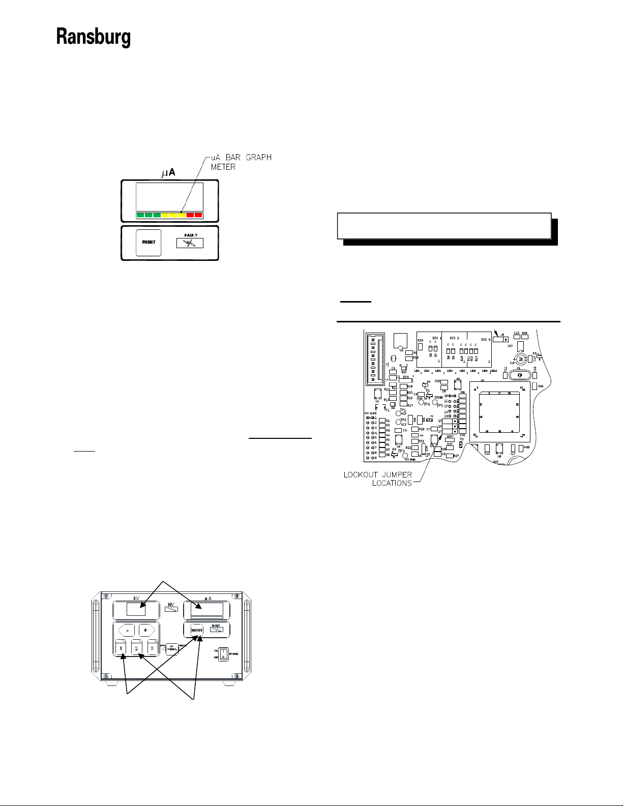
The kV setpoint is displayed on the kV display,
the actual current draw on the µA display, and
the high voltage light illuminates. Under the µA
display is a bar graph meter that illuminates
according to the actual current draw shown in
Figure 16. The green and yellow regions of the
bar graphs meter indicate output current is in
the optimum range for maximum transfer
21 CP-13-07.2
9060 Cascade Low Voltage Controller - Operation
efficiency. The red region of the bar graph
indicates high output current causing decreased
transfer efficiency. If high output, check maintenance of applicator and external equipment of
the power supply .
Figure 16: µA Bar Graph Meter Display
Measuring “High Voltage On”
Time
The 9060 Cascade Low Voltage Controller
records the amount of time the high voltage is
triggered on up to 99,999 hours. This value is
display on the kV and µA displays of the unit.
There are two registers that retain this information, one that may be reset, the other that is
permanently retained in memory. The number
of hours the unit’s high voltage has been on
may be displayed by depressing at the same
time the preset 1 and reset buttons (See Figure
17). The display will show hours of use for 3
seconds. This is the resettable register.
To reset this register, press the reset button
while the hours are displayed.
To view the non-resettable register, press the
preset 2 and reset buttons at the same time.
This display will show the hours for 3 seconds.
Display of “HV ON” Time in Hours
LOCKOUTS
There are lockouts that may be done at the PC
board (see Figure 18). These lockouts may be
used individually or in combination as required.
If the jumpers are disconnected, the original
functions are re-enabled. After changing any
jumpers, the AC power must cycled for the new
setting to take affect.
Some lockouts are sealed using sealant
to prevent them from being modified for
safety reasons. These lockouts should
ONLY be modified by Ransburg Authorized
Representatives.
Figure 18: Lockout Jumper Location
Front Panel Lockout
This feature locks out any changes to the kV
setting from the front panel of the Controller.
1.
Set the kV to the desired value using the
front panel buttons. This must be set prior
to installing the jumper.
N O T E
2.
Turn AC power off and access the interior of
the Controller.
3.
Place the jumper across the two (2) pins at
location 16 on the main PC board (See
Figure 19).
Press and hold
Both For Resettable
On Time Register
Figure 17: Display “High Voltage On”
Press and hold
Both For Non-Resettable
On Time Register
4.
Close the Controller and turn AC power
back on. Pressing the front panel +, -, or
setpoint buttons will now have no affect on
the kV setting.
CP-13-07.2 22

9060 Cascade Low Voltage Controller - Operation
Figure 21: Lockout Jumper Location
Figure 19: Jumper Location - Front
Panel Lockout
Overload
The overload circuit may be activated for
applications that require overload indication or
notification of high current draws of the applicator. The default overload value is set in the
software to the maximum microamp rating
minus 10 microamps.
1.
Turn AC power off and access the interior of
the Controller.
2.
Place the jumper across the two (2) pins at
location 17 on the main PC board (See
Figure 20).
3.
Close the Controller and turn AC power
back on. An overload fault will now occur if
the microamp display exceeds the overload
value.
KV TEST JUMPER
To assist in testing and troubleshooting, a
jumper (J8) has been added to the main PC
board. By covering (shorting) both terminals of
this jumper, the high voltage of the spray
applicator can be activated. Thus, for testing
and troubleshooting, high voltage output can be
obtained without the need to trigger air through
the spray applicator. After testing, the jumper
must be repositioned so that it covers only
one terminal (open) or the high voltage will
stay on all the time. See Figure 21 for the
location of test jumper J8.
If jumper J8 is left covering (shorting)
both terminals, high voltage will be on
whenever the AC power is turned on.
W A R N I N G
!
N O T E
Use Ransburg Calibrated Equipment
ONLY for testing and troubleshooting. Refer to the “Accessories” section of this manual for part numbers for testing equipment.
SETPOINT
OPERATIONS
Voltage Setpoints
Figure 20: Jumper Location - Overload
23 CP-13-07.2
The voltage on the 9060 Cascade Low Voltage
Controller is adjustable between 20 kV and full

9060 Cascade Low Voltage Controller - Operation
kV DC. There are 3 voltage setpoints (presets);
1, 2, and 3. Each of these setpoints can be
individually adjusted between 20 kV and full kV
DC. The three (3) factory preset voltages are
listed in the following table:
Factory Presets
Preset Value
1 Full kV minus 20 kV
2 Full kV minus 10 kV
3 Full kV
The full kV DC value is determined by
the gun type configuration for the particular applicator that is being used, NOT the
full KV value of the cascade.
N O T E
Setting the Setpoint
When the applicator is off, the present setpoint
can be changed by pressing the 1, 2, or 3
buttons on the front panel shown in Figure 22.
The setpoint that is currently selected will have
the LED light in the upper right corner of the
button lit.
and - buttons on the front panel of the 9060
Controller shown in Figure 22. Single pushes
of the + or - buttons will increment or decrement
the currently selected preset in units of 1.
When the + or - buttons are held in for longer
than a 1/2 second, the kV display will begin
incrementing or decrementing in units of five
(5).
Resetting Faults
During operation, various faults can occur
based upon the operating conditions or if any
problems with the 9060 unit arise. If a fault
occurs, to reset a fault, the trigger of the gun
MUST be off and then press the Reset Button .
This will clear the fault status and put the unit
back into operation unless a fault condition is
still present. Please refer to the “Fault Description” portion of the Operation Section of this
Service manual for more information on a
specific fault and how to correct it.
There is a 5 second fault reset delay
timer that inhibits the triggering of high
voltage immediately after a fault reset.
N O T E
Single Pushes Increment Voltage Down (-) or Up
(+)in Single Increments. Holding Button Increments
Voltage Down (-) or Up (+) in Increments of 5 kV.
Set Point Select Button
Figure 22: kV Adjust/Setpoint Buttons
Adjusting Presets
To adjust one of the preset setpoints, ensure
the applicator is off in local mode and select the
desired setpoint by pressing the corresponding
setpoint button. The setpoint can then be
adjusted between 20 kV and full kV using the +
CP-13-07.2 24
FAULT DESCRIPTIONS
For in depth troubleshooting information on the
9060, please refer to the “Fault Troubleshooting” portion of the Maintenance Section of this
service manual. If a fault occurs, the Fault
Indicator on the front of the Controller will light
and a fault code will be displayed on the
microamp display. Faults can be reset by
pressing the Reset button on the front of the
Controller or by using the remote I/O reset
signal.
Any fault code not listed that appear on
the screen are a likely indication of a PC
board failure due to possible arc damage.
N O T E

9060 Cascade Low Voltage Controller - Operation
Cable Fault (CF)
This fault will occur if high voltage is active and
the microprocessor detects that no current is
being supplied to the applicator. This indicates
a connection problem from the control unit to
the handgun barrel assembly. Typical causes
include a faulty low voltage cable, stuck pins on
the plug assembly, or contaminated contacts on
the applicator. This may also indicate a faulty
barrel assembly for a handgun. For additional
information, refer to the Fault Troubleshooting
Section.
Overload Fault (OL)
This fault will occur if the overload feature is
active (see ‘Overload Activation” previously in
the “Operation” section) and the output current
exceeds the overload current value. This can
be caused by excessive overspray on the applicator or paint formulation that is too conductive. Clean the applicator, check the paint formulation, or move overload jumper (JP17) to
the open position.
Figure 23: Cable Fault Display
Ground Fault (GF)
If this fault occurs, the fault indicator on the
control unit will illuminate, a GF indication will
show in the uA display. This fault will occur if
the microprocessor detects a loss of ground at
the high voltage section. If this fault occurs,
reset the fault. This fault can be caused by a
broken ground path between the handgun and
the control unit and may indicate a faulty cable
or plug assembly. For more information, refer
to Fault Troubleshooting Section.
Figure 25: Overload Fault Display
Current Limit Fault (CL)
This fault occurs if the output current exceeds
the maximum current by 20µA. This fault can
be caused by excessive overspray on the applicator or a paint formulation that is too conductive. It may also be caused by a failed
handgun barrel or faulty pc board. Clean the
applicator, check the paint formulation, and retest. See Fault Troubleshooting Section for
more information.
Figure 26: Current Limit Fault Display
Figure 24: Ground Fault Display
25 CP-13-07.2

9060 Cascade Low Voltage Controller - Operation
Voltage Cable Fault (UC)
This fault will occur if the microprocessor detects a loss of the voltage feedback signal.
This may indicate a failed pc board. See Fault
Troubleshooting Section for more information.
Figure 27: Voltage Cable Fault Display
Over Voltage Fault (OU)
This fault will occur if the microprocessor detects the unit is trying to output voltage above
the required for the specific applicator type. If
this occurs, reset the Controller. If this fault
continues to occur, replace the main PC
board.
Feedback Fault (FF)
This fault will occur if the microprocessor detects a loss of the current feedback signal. If
this occurs, reset the fault. If this fault occurs
repeatedly, replace the handgun barrel or the
pc board.
Figure 29: Feedback Fault Display
Boot Fault (bF)
This fault will occur during the start-up sequence if an active trigger signal is present. It
is designed to prevent immediate triggering
after start-up as the unit should be allowed to
enter the “ready” state prior to being triggered.
This fault also prevents the high voltage from
being fired if the microprocessor resets. For
additional information, refer to the Fault Troubleshooting Section.
Figure 28: Over Voltage Fault Display
Figure 30: Boot Fault Display
CP-13-07.2 26

9060 Cascade Low Voltage Controller - Maintenance
MAINTENANCE
TROUBLESHOOTING GUIDE
General Problem Possible Cause Solution
Blank Display
1. No power
2. Blown fuse
1. Check the power connections and verify
they are fully connected and power is available. Power cycle the unit off and back on.
2. Check Fuses and replace if blown using
the replacement fuses inside the lid of the
unit.
FAULT TROUBLESHOOTING GUIDE
Before troubleshooting gun and control unit problems, flush the gun with solvent and purge
with air. Some of the tests will require high voltage to be applied to the gun, so the gun must
be empty of paint and solvent.
W A R N I N G
!
Fault Description Solution
Cable Fault (CF)
27 CP-13-07.2
The Cable Fault indicates the control unit does not detect a high
voltage section on the end of the
cable. The fault typically occurs at
a high voltage trigger.
1. Check for a loose connection on the low
voltage cable and tighten if necessary.
Insure both connectors are secure and retest for CF fault.
2. Replace low voltage cable and re-test.
3. Send unit in for repair.

9060 Cascade Low Voltage Controller - Maintenance
Fault Description Solution
Ground Fault (GF)
Over-Voltage Fault
(OU)
Over-Load Fault
(OL)
The Ground Fault is typically
caused by a ground connection
problem, and can create a safety
hazard. It can occur without high
voltage and will not reset.
The Over Voltage Fault indicates
the output voltage exceeds the
design specifications. It typically
occurs during a high voltage trigger.
The Over Load Fault indicates the
current output has exceeded the
overload threshold. This fault is
only active if jumper 17 is shorted.
The overload threshold is normally
set at 10 µA below the maximum
output of the applicator.
1. Check for loose connection on the low voltage cable, and tighten if necessary. Insure
both connectors are secure and re-test for
GF fault.
2. Turn off control unit power. Measure resistance from ground to handgun air inlet
fitting-if greater than 5 ohms, replace low
voltage cable and re-test.
3. Send unit in for repair.
1. Check connections using two finger pull
test to ensure they are connected.
2. Replace the main pc board.
3. Send high voltage control unit in for repair.
1. This may indicate the paint conductivity is
too high (resistance too low) or the outside
of the applicator is contaminated with paint.
Test paint for proper conductivity or clean
applicator with non-polar solvent. Ensure
dump lines are clean.
Current Limit Fault
(CL)
Feedback Fault
(FF)
The Current Limit Fault indicates
the current output of the gun has
exceeded the maximum allowable
output current. It typically occurs
with the high voltage on.
The Feedback Fault indicates
there is no current feedback or it
is incorrect. It typically occurs
with the high voltage on.
1. This may indicate the paint conductivity is
too high (resistance too low) or the outside
of the applicator is contaminated with paint.
Test paint for proper conductivity or clean
applicator with non-polar solvent. Ensure
dump lines are clean.
2. Replace applicator and re-test. If problem
still exists, replace main pc board.
3. Send applicator in for repair.
1. Replace handgun barrel assembly.
2. Send low voltage controller in for repair.
CP-13-07.2 28

9060 Cascade Low Voltage Controller - Maintenance
Fault Description Solution
Voltage Cable
Fault (UC)
Boot Fault (bF)
The Voltage Feedback Fault indicates the cascade drive signal is
not present. It typically occurs
when high voltage is triggered.
The Boot Fault indicates that an
active trigger signal was detected
during the start-up sequence.
1. Replace the barrel assembly and re-test.
2. Replace the main pc board and re-test.
1. Turn off the voltage controller.
2. Ensure that the gun trigger is not pressed
so the remote trigger input signal is not active.
3. Turn on the voltage controller to verify that
a trigger signal is not present and that the
unit enters the ‘ready’ state.
4. Send the voltage controller in for repair or
contact technical support.
29 CP-13-07.2

9060 Cascade Low Voltage Controller - Maintenance
N O T E S
CP-13-07.2 30

9060 Cascade Low Voltage Controller - Parts Identification
PARTS IDENTIFICATION
9060 CASCASDE LOW VOLTAGE CONTROLLER MODEL
IDENTIFICATION *
When ordering, use 80131-A1B as indicated by Table A and B. Three digits must follow the basic
part number, for example:
80131 - A 1 B
Basic Part Number
Model Selection
(TABLE A)
* Model number and serial number of the voltage controller is located on the left outside face of
the main enclosure.
Table A - Model Selection
Dash No.
2 Vector R70AS Handgun
3 Vector R90AS Handgun
4 Vector AA90 Handgun
5 Vector R90AS Waterborne Handgun
Description
Handgun Model Reference
Model
79501-XXX Vector R70AS Handgun
79500-XXX Vector R90AS Handgun
79580-XXX Vector AA90 Handgun
79523-XXX Vector R90AS Waterborne Handgun
Description
Plug Selection
(TABLE B)
Table B - Plug Selection
Dash No.
Description
Domestic
1
2 Europe
3 China
31 CP-13-07.2

9060 Cascade Low Voltage Controller - Parts Identification
9060 Cascade Low Voltage Controller - Parts List
Part #
13742-01 Air Flow Switch (80131-21X, 31X, 51X Units)
13742-02 Air Flow Switch (80131-41X Units)
72771-06 Fuse (250V, 1A, 5mm x 20mm)
79390-20 9060 Cascade Low Voltage Controller PC Mainboard for 80131-21X
79390-22 9060 Cascade Low Voltage Controller PC Mainboard for 80131-31X, 51X
79390-24 9060 Cascade Low Voltage Controller PC Mainboard for 80131-41X
79428-00 Power Supply, 24V (24VDC Power Supply 1PS)
76434-01 Switch, Rocker (On-Off Switch)
Description
Figure 31: Part Identifications
CP-13-07.2 32

9060 High Voltage Controller - Accessories
ACCESSORIES
9060 Low Voltage Controller - Accessories List
Part #
76652-01 HV Probe
76652-02 Meter w/Test Leads
76652-03 Paint Test Probe w/Meter
76652-04 Deluxe Kit (Include HV Probe, Meter w/Test Leads, and Paint Test Probe)
Description
33 CP-13-07.2

9060 High Voltage Controller
CP-13-07.2 34

9060 Cascade Low Voltage Controller - Warranty Policies
WARRANTY POLICIES
LIMITED WARRANTY
Ransburg will replace or repair without charge
any part and/or equipment that falls within the
specified time (see below) because of faulty
workmanship or material, provided that the
equipment has been used and maintained in
accordance with Ransburg's written safety and
operating instructions, and has been used
under normal operating conditions. Normal
wear items are excluded.
THE USE OF OTHER THAN RANSBURG
APPROVED PARTS, VOID ALL WARRANTIES.
SPARE PARTS: One hundred and eighty (180)
days from date of purchase, except for rebuilt
parts (any part number ending in "R") for which
the warranty period is ninety (90) days.
EQUIPMENT: When purchased as a complete
unit, (i.e., guns, power supplies, control units,
etc.), is one (1) year from date of purchase.
WRAPPING THE APPLICATOR, ASSOCIATED VALVES AND TUBING, AND
SUPPORTING HARDWARE IN PLASTIC,
SHRINK-WRAP, OR ANY OTHER NONAPPROVED COVERING, WILL VOID THIS
WARRANTY.
RANSBURG'S ONLY OBLIGATION UNDER THIS WARRANTY IS TO REPLACE
PARTS THAT HAVE FAILED BECAUSE
OF FAULTY WORKMANSHIP OR MATERIALS. THERE ARE NO IMPLIED WARRANTIES NOR WARRANTIES OF EITHER
MERCHANTABILITY OR FITNESS FOR A
PARTICULAR PURPOSE. RANSBURG
ASSUMES NO LIABILITY FOR INJURY,
DAMAGE TO PROPERTY OR FOR
CONSEQUENTIAL DAMAGES FOR LOSS
OF GOODWILL OR PRODUCTION OR
INCOME, WHICH RESULT FROM USE OR
MISUSE OF THE EQUIPMENT BY
PURCHASER OR OTHERS.
EXCLUSIONS:
If, in Ransburg's opinion the warranty item in
question, or other items damaged by this
part was improperly installed, operated or
maintained, Ransburg will assume no
responsibility for repair or replacement of the
item or items. The purchaser, therefore will
assume all responsibility for any cost of
repair or replacement and service related
costs if applicable.
35 CP-13-07.2

9060 Cascade Low Voltage Controller - Warranty Policies
Manufacturing
1910 North Wayne Street
Angola, Indiana 46703-9100
Telephone: 260-665-8800
Fax: 260-665-8516
Technical Service—Assistance
320 Philips Ave.
Toledo, Ohio 43612-1493
Telephone (toll free): 800-233-3366
Fax: 419-470-2233
Technical Support Representative will direct you to the appropriate telephone number for
ordering Spare Parts.
Form No. CP-13-07.2
© 2013 Ransburg. All rights reserved. Litho in U.S.A.
Models and specifications subject to change without notice. 05/13
CP-13-07.2 36
 Loading...