

Page 1
DATA S H E ET
General Description
The RaneGain test set is a handy tool kit based on techniques first developed by Pat Brown1 of Syn-Aud-Con for use
in quickly setting sound system gain controls. Using the
RaneGain pair makes correctly setting level controls a snap.
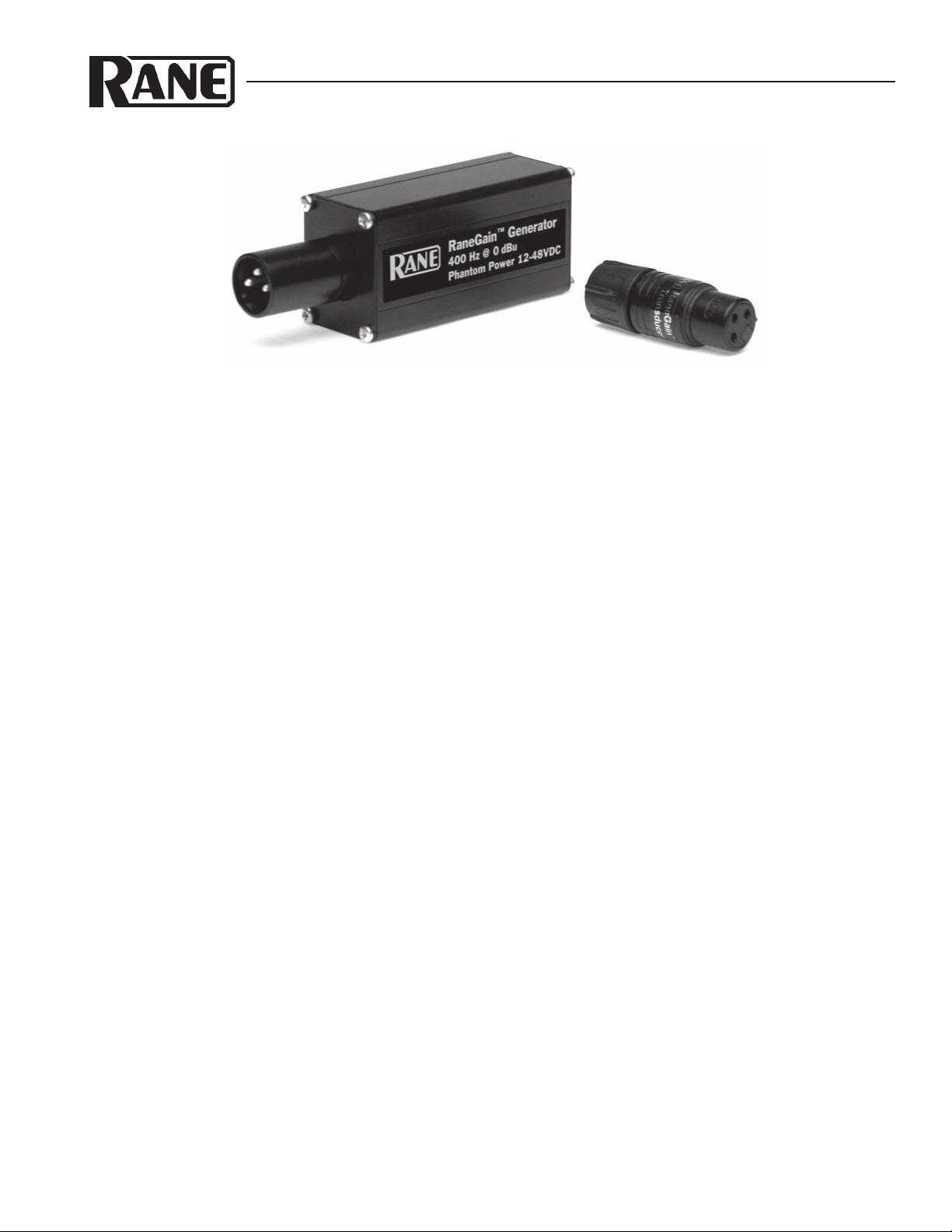
Comprised of a precision 400 Hz sine wave Generator and
a matching piezo Transducer, the test set makes use of the
Fourier principle that all periodic waves can be broken down
into a sum of pure sine waves. If a pure 400 Hz tone is the
source in a system, and the system is turned up until clipping,
then what comes out is the 400 Hz fundamental, plus a whole
string of predominately odd-order harmonics. Spectrum
analysis of the output will show the 400 Hz fundamental, plus
strong harmonics at the odd harmonic intervals of 1.2 kHz, 2
kHz, 2.8 kHz, 3.6 kHz, 4.4 kHz and so on. The RaneGain
Transducer is a piezo tweeter designed to reproduce mid-tohigh audio frequencies, so while it doesn’t reproduce the 400
Hz fundamental worth a hoot, the harmonics make it scream.
Operation
PRESET ALL LEVEL CONTROLS IN THE SYSTEM
After all equipment is hooked-up, verify system operation
by sending an audio signal through it. Do this first before
trying to set any gain/level controls. This is to make sure all
wiring has been done correctly, that there are no bad cables,
and that there is no audible hum or buzz being picked up by
improperly grounded interconnections (See RaneNote 110).
Once you are sure the system is operating quietly and
correctly, then you are ready to proceed.
Turn down all power amplifier level/sensitivity controls.
Turn off all power amplifiers. (This allows you to set the
maximum signal level through the system without making
yourself and others stark raving mad.)
Set all gain/level controls to their off or minimum settings.
Defeat all dynamic controllers such as compressors/
limiters, gate/expanders, and enhancers by setting the Ratio
controls to 1:1, and/or turning the Threshold controls way up
(or down for gate/expanders).
Use no equalization until after correctly setting the gain.
RaneGain
GENERATOR & TRANSDUCER
CONSOLE/MIC PREAMP GAIN SETTINGS
A detailed discussion of how to run a mixing console lies
outside the range of this Note, but a few observations are
relevant. Think about the typical mixer signal path. At its
most basic, each input channel consists of a mic stage, some
EQ, routing assign switches and level controls, along with a
channel master fader. All of these input channels are then
mixed together to form various outputs, each with its own
level control or fader. To set the proper mixer gain structure,
you want to maximize the overall S/N (signal-to-noise) ratio.
Now think about that a little: because of the physics behind
analog electronics, each stage contributes noise as the signal
travels through it. (Digital is a bit different and is left to
another Note and another day.) Therefore each stage works to
degrade the overall signal-to-noise ratio. Here’s the important
part: The amount of noise contributed by each stage is
(relatively) independent of the signal level passing through it.
So, the bigger the input signal, the better the output S/N ratio
(in general).
The rule here is to take as much gain as necessary to bring
the signal up to the desired average level, say, +4 dBu, as
soon as possible. If you need 60 dB of gain to bring up a mic
input, you don’t want to do it with 20 dB here, 20 dB there,
and 20 dB some other place. You want to do it all at once at
the input mic stage. For most applications, the entire system
S/N (more or less) gets fixed at the mic stage. Therefore set it
for as much gain as possible without excessive clipping. Note
the wording excessive clipping. A little clipping is not audible
in the overall scheme of things. Test the source for its
expected maximum input level. This means, one at a time,
having the singers sing, and the players play, as loud as they
expect to sing/play during the performance. Or, if the source
Page 2

RaneGain
GENERATOR & TRANSDUCER
is recorded, or off-the-air, turn it up as loud as ever expected.
Set the input mic gain trim so the mic OL (overload) light just
occasionally flickers. This is as much gain as can be taken
with this stage. Any more and it will clip all the time; any less
and you are hurting your best possible S/N.
(Note that a simple single mic preamp is set up in the
same manner as a whole mixing console.)
OUTBOARD GEAR I/O LEVEL CONTROLS
All outboard unit level controls (except active crossovers
— see below) exist primarily for two reasons:
• They provide the flexibility to operate with all signal sizes.
If the input signal is too small, a gain control brings it up to
the desired average level, and if the signal is too large, an
attenuator reduces it back to the desired average.
• Level controls for equalizers: the need to provide make-up
gain in the case where significant cutting of the signal
makes it too small, or the opposite case, where a lot of
boosting makes the overall signal too large, requiring
attenuation.
Many outboard units operate at “unity gain,” and do not
have any level controls — what comes in (magnitude-wise) is
what comes out. For a perfect system, all outboard gear
would operate in a unity gain fashion. It is the main console’s
(or preamp’s) job to add whatever gain is required to all input
signals. After that, all outboard compressors, limiters,
equalizers, enhancers, effects, or what-have-you need not
provide gain beyond that required to offset the amplification
or attenuation the box provides.
With that said, you can now move ahead with setting
whatever level controls do exist in the system.
Whether the system contains one piece of outboard gear,
or a dozen, gains are all set the same way. Again, the rule is
to maximize the S/N through each piece of equipment,
thereby maximizing the S/N of the whole system. And that
means setting things such that your maximum system signal
goes straight through every box without clipping.
SETTING SIGNAL PROCESSING LEVEL CONTROLS
First, a sound source is connected to the mixing console (or
separate mic preamp) to provide the maximum system signal
output, then this signal is used to set the outboard units.
Connect the RainGain (RG) Generator to an unused
channel in the mixing console or to the input of the mic
preamp. Carefully set the channel input fader so the mic stage
does not overload. Next, plug the RG Transducer into the
console’s (or preamp’s) master balanced output XLR jack.
Turn up the master output fader (or preamp output level
control) until the Transducer first sounds; reduce the level
until the Transducer stops. This is now the maximum system
signal output.
Outboard gear gain/level controls fall into three categories:
• No controls
• One control, either Input or Output
• Both Input & Output Controls
Obviously, the first category is not a problem!
If there is only one level control, regardless of its location,
set it to give the maximum output level using the RG Transducer.
With two controls it is very important to set the Input
control first. Do this by turning up the Output control just
enough to pass the signal without clipping. Set the Input
control to barely buzz the RG Transducer, then back it down a
hair. Now set the Output control also to just buzzing.
For Rane digital audio products, like the RPM 26v
Multiprocessor where input A/D (analog-to-digital) metering
is provided with the RW 232 software, setting the input level
gain is particularly easy and extremely important: Using the
maximum system signal as the input, open up the Input Trim
box and simply slide the control until the 0 dBFS indicator
begins lighting. This indicates the onset of “digital clipping,”
and is definitely something you want to avoid, so this is the
maximum gain point.
See RaneNote 135 “Setting Sound System Level Controls”
for setting active crossovers and power amplifiers.
Specifications
Generator
Frequency: 400 Hz (±10%) Sine Wave
Level: 0 dBu (±1 dB)
Phantom Power (Required): 12-48 VDC
THD: 2% max
Transducer
Type: Piezo
Capacitance: 10,000 pF (±30%) (40,000 ohms @ 400 Hz)
Max Voltage: +26 dBu
Max Current: 2 mA
Life: 500 Hours (average)
References
1. Pat Brown, “Piezo Magic,” The Syn-Aud-Con Newsletter,
Vol. 24, No. 2, Spring 1996.
2. Dennis Bohn “Setting Sound System Level Controls,”
RaneNote 135 (Rane Corporation, 1997)
©Rane Corporation 10802 47th Ave. W., Mukilteo WA 98275-5098 TEL (425)355-6000 FAX (425)347-7757 WEB http://www.rane.com
All features & specifications subject to change without notice DOC 104300 PN 11609
 Loading...