

Page 1
DATA SH EE T
CUT
+
0
6
•
5
1
4
•
3
2
2
•
1
3
0
A
•
1
4
2
•
3
5
4
•
5
6
6
CUT
+
0
6
•
5
1
4
•
3
2
2
•
1
3
0
B
•
1
4
2
•
3
5
4
•
5
6
6
General Description
When the term “graphic equalizer” was rst coined, the intent
was to provide a device that allowed the user to “draw” the desired
frequency response using slider controls on the unit’s front panel.
us, the Holy Grail of graphic equalizers is a device with a
response that truly matches the slider settings. For years, this
seemingly unobtainable goal resulted in products based on the
ne art of compromise … until the DEQ 60L.
It’s not Constant—not Proportional—It’s Perfect! Digital
Signal Processing (DSP) allows lter technology not possible with
analog designs. Rane coined the term Perfect-Q™ to describe the
results (U.S. patent 7,266,205). e DEQ 60L is the rst true
graphic equalizer (i.e., one providing real mechanical front panel
slide controls) whose output response precisely matches its front
panel settings. Perfect-Q features virtually no band interaction
and extremely low ripple between adjacent bands. To keep things
exible, fear not proportional-Q lovers, each channel of the DEQ
60L is selectable between Perfect-Q or Proportional-Q response.
For all the details, read the RaneNote “Perfect-Q, the Next
Step in Graphic EQ Design” available at the Rane website.
DEQ 60L
GRAPHIC EQUALIZER
CUT FI L TER S TONE LEVEL
3 dB
error
+
12
5k
12
7k
0
0
10k
14k
20k 15
12
12
+
+
5k
12
12
7k
0
0
10k
14k
12
12
20k 15
+
BY P AS S
A
B EQ
DEQ 60L
GRAPHIC EQUALIZER
BY P AS S
A
EQ
B
CU T -ON L Y
PERFEC T -Q ™
PROPO R T - Q
+6 -12 -6 -3 0 +3 +12 OL
PERFEC T -Q ™
PROPO R T - Q
+6 -12 -6 -3 0 +3 +12 OL
POWER
±12
±6
IN
A
OUT
±12
±6
IN
B
OUT
Rane Perfect-Q™
Proportional-Q
6 dB
error
CUT
+
0
12
1
10
2
8
3
6
4
4
5
2
6
0
7
2
8
4
9
6
10
8
11
10
12
12
5.0k 25 31.5 40 50 63 80 100 800 125 160 200 250 500 400 315 630 2.0k 1.25k 1.0k 1.6k 3.15k 2.5k 4.0k 12.5k 8.0k 6.3k 10k 16k 20k LOW MID HIGH LOW HIGH IN OUT
CUT
+
0
12
1
10
2
8
3
6
4
4
5
2
6
0
7
2
8
4
9
6
10
8
11
10
12
12
+
6
240
120
0
60
30
∞
+
6
240
120
0
60
30
∞
e DEQ 60L features 45 mm sliders, a switchable Cut-Only
mode, additional Cut lters, and additional 3-band Tone controls. e DEQ 60L provides the most complete set of pure EQ
functions ever oered in an analog controlled equalizer.
4 dB
error
31.5 40 50 63 80 100125 160 200 250 315 400 500 630 8001.0k1.25k 1.6k 2.0k 2.5k 3. 15k 4.0k 5.0k 6.3k 8.0k 10k 12.5k 16k 20
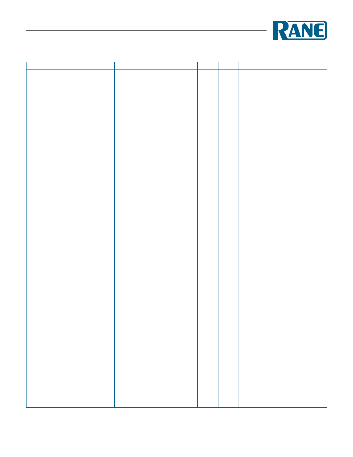
Typical PA adjustment showing the dierence between Perfect-Q and
Features
• Perfect-Q™: What You See Is What You Get (No lter interaction)
• Proportional-Q: Classic smooth response
• Independent Accelerated-Slope™ 3-band full-cut tone controls
• Low-Cut and High-Cut Filters
• Input and Output Level controls
• Each channel may use A or B channel controls:
· Stereo Linking
· Two “analog memories”
· A-curve / B-curve comparison
Proportional-Q. Which curve matches the slider positions?
• 45 mm sliders with center detents
• Two Boost / Cut ranges: ±6 dB or ±12 dB
• Switchable Cut-Only mode
• Eight segment metering for each Input and Output
• Analog controlled DSP
• XLR, TRS and Euroblock connectors
• Bypass switch (DSP), Bypass relay (power failure)
• Exceptional RF and magnetic immunity
• Universal internal switching power supply (100-240 VAC)
Data Sheet-1
Page 2
DEQ 60L
GRAPHIC EQUALIZER
Features and Specifications
Parameter Specication Limit Units Conditions/Comments
Inputs: Type Active Balanced
..........Connectors XLR, ¼" TRS, Euroblock XLR pin 2 hot per AES standards
..........Maximum Input +22 1 dBu 1 kHz
..........Common Mode Rejection 60 typ. dB 1 kHz
..........Impedance 14.6k 1% Ω Each leg to ground @ 1 kHz
DSP Block: Dynamic Range 106 typ. dB A-weighted (input to output); unity
24-bit Converters: Sample Rate 48 kHz
Propagation Delay 1.29 typ. ms
Input Level: Range ±12 dB
Output Level: Range ±12 dB
Graphic EQ: Bands 30 ⅓-octave ISO spacing Hz 25 Hz to 20 kHz
..........Type Perfect-Q or Proportional-Q Switchable, each channel
..........Range ±6 or ±12 dB Switchable, each channel
..........Slider Travel 45 mm Center detent = 0 dB
Tone Controls 3-band; Accelerated Slope™ 2nd-order, phase 0º @ unity gain
..........Range +6 to o dB Center detent = 0 dB
..........Low/Mid Crossover Point 300 Hz
..........Mid/High Crossover Point 4 kHz
Low-Cut Filter 15-2 4 0 Hz
High-Cut Filter 5-20 kHz
Meters Input and Output Each channel
..........Type Peak responding dBu Peak-dBu is displayed for 1.5 sec
..........Attack/Decay 0/50 0 typ. ms per 20 dB step
Bypass: Power Failure Automatic relay bypass Input wired to Output
Bypass Switch Mode Each channel
..........Rear switch: Bypass A ll Filters and levels bypassed By front panel bypass
..........Rear switch: Bypass Filters Filters bypassed By front panel bypass
A/B Switches Determine controls to channel Bypass and A/B not aected
Outputs: Active Balanced
..........Connectors XLR, ¼" TRS, Euroblock XLR pin 2 hot per AES standards
..........Impedance 100 1% Ω Each leg to ground
..........Maximum Output +22 1 dBu 600 Ω or greater
EMI Filters Yes Inputs and Outputs
Frequency Response 15 Hz to 20 kHz +0/-3 dB
THD+Noise .02 typ. % +4 dBu, 20-20 kHz, 20 kHz BW
THD+Noise .006 typ. % +4 dBu, 1 kHz, 20 kHz BW
Crosstalk <-100 typ. dB 2 kHz
Power Supply Requirement 100 to 240 VAC 50/60 Hz, 20 W
Unit: Agency Listing UL/cUL/CE
Unit: Construction All Steel
..........Size 5.25" H x 19" W x 8.25" D (3U) (13.3 cm x 48.3 cm x 21 cm)
..........Weight 11 lb (5 kg)
..........Shipping: Size 11" x 23" x 16" (27.9 cm x 58.4 cm x 40.6 cm)
..........Weight 18 lb (8.1 kg)
Note: 0 dBu=0.775 Vrms
Data Sheet-2
Page 3

INPUT A
2
3
1
DEQ 60L
GRAPHIC EQUALIZER
Block Diagram
OUTPUT A
+
-
+
2
-
3
1
INPUT B
2
3
1
A
CONTROL
B
A / B
A
B
+
VC
FAIL-SAFE RELAY
DIGITAL SIGNAL PROCESSING
(EACH CHANNEL)
+
-
INPUT
LEVEL
ADC DAC
C
D
Perfect-Q Proport-Q ±6 ±12
BOOST / CUT
30 BAND GRAPHIC
WITH
PERFECT-Q
BYPASS ALL
INPUT OUTPUT
dBFS
OL
+12
+6
+3
0
-3
-6
-12
BYPASS FILTERS
CUT-ONLY
dBFS
OL
+12
+6
+3
0
-3
-6
-12
SPLIT-BAND
FULL-CUT
TONE CONTROL
12 dB / OCT.
OUTPUT
LEVEL
C
D
+
Vc
FAIL-SAFE RELAY
OUTPUT B
+
2
-
3
1
25 Hz 20 kHz MID
Architectural Specifications
e equalizer shall be analog-controlled, with all control provided
on the front panel using 45 mm DEQ 60L linear sliders with dust
dams. A detented and guaranteed 0 dB point shall be provided on
these linear sliders. All signal processing shall be accomplished using high accuracy digital signal processing. e equalizer shall be
a two channel model, and each channel shall have thirty (30) frequency bands located on standard ISO center frequencies. Each
band shall have a bandwidth of 1/3-octave. e equalizer shall be
front-panel switchable between two modes, Proportional-Q or
Perfect-Q. e equalizer shall have a front panel switch selecting
cut-only or boost/cut operation.
Low and high cut lters shall be provided with 12 dB/octave
slopes and adjustable corner frequencies. Tone controls shall be
provided for low, mid and high frequencies. e tone controls
shall have a range of +6 dB to o.
LOWLOW HIGHHIGH
CUT CUT
Input and output level controls shall be provided for each
channel. Input and output peak dBu meters shall be provided.
e unit shall provide an automatic passive bypass feature when
power is not available, and active bypass switches for each channel
when the unit is operating.
e inputs and outputs shall be active balanced/unbalanced
designs terminated with XLR, 1/4" TRS (tip-ring-sleeve), and
Euroblock terminals. e outputs shall have equal output impedances. RFI lters shall be provided.
e unit shall meet CE and UL agency safety requirements
and be powered from an internal universal power supply (100
to 240 VAC) via a rear panel IEC connector. e unit enclosure
shall be constructed entirely from cold-rolled steel. e unit shall
be supplied with ears for mounting into a standard 3U EIA rack.
e unit shall be a Rane DEQ 60L Graphic Equalizer.
Data Sheet-3
Page 4

DEQ 60L
FILTERSALL
+
-
ACN 001 345 482
100-240V
50/60 Hz 20 WATTS
DEQ 60L
MADE IN U.S.A.
RANE CORP.
FOR CONTINUED
GROUNDING
PROTECTION
DO NOT REMOVE
SCREW
This device complies with Part 15 of the FCC Rules. Operation is
subject to the following two conditions: (1) this device may not cause
harmful interference, and (2) this device must accept any interference
received, including interference that may cause undesired operation.
+
-
+
-
+
-
+
-
+
-
+
-
+
-
WIRING
TIP / PIN 2 = POSITIVE
RING / PIN 3 = NEGATIVE
SLEEVE = SIGNAL GROUND
PIN 1 = CHASSIS GROUND
OUTPUT B
BYPASS
OUTPUT A INPUT B INPUT A
U.S. PATENT 7,266,205
COMMERCIAL AUDIO
EQUIPMENT 24TJ
R
-14
+14
-12
-10
-8
-6
-4
-2
+0
+2
+4
+6
+8
+10
+12
-2 +2-1.75 -1.5 -1.25 -1 -0.75 -0.5 -0.25 +0 +0.25 +0.5 +0.75 +1 +1.25 +1.5 +1.75
d
B
u
octaves
individual responses
(actual slider settings)
combined response
showing effects of
band interaction
-14
+14
-12
-10
-8
-6
-4
-2
+0
+2
+4
+6
+8
+10
+12
-2 +2-1.75 -1.5 -1.25 -1 -0.75 -0.5 -0.25 +0 +0.25 +0.5 +0.75 +1 +1.25 +1.5 +1.75
d
B
u
octaves
individual responses
(actual slider settings)
no band interaction or ripple
combined response
is perfect
0
+2
+4
+6
+8
+10
+12
-2-3-4 234-1 01
-40
-35
-30
-25
-20
-15
-10
-5
0
5
10
20 100 1k 10k 20k
Low O,
Mid ‘0’,
Hi O
Low ‘0’, Mid +6, Hi ‘0’
Low ‘0’,
Mid O,
Hi ‘0’
Low +6, Mid ‘0’, Hi +6
GRAPHIC EQUALIZER
Rear Panel
Figure 1. Band interaction of 1/3-octave Proportional-Q lters
Figure 2. Graphic response of Perfect-Q lters
References
1. R. Miller , R. Jes, S. Radford, D. Bohn, “Perfect-Q, the
Next Step in Graphic EQ Design,” RaneNote, (2003).
©Rane Corporation 10802 47th Ave. W., Mukilteo WA 98275-5098 USA TEL 425-355-6000 FAX 425-347-7757 WEB www.rane.com
Data Sheet-4
Figure 3. Phase response of Figures 1 and 2.
Figure 5. The interactive operation of the 3 Tone controls
Accessory
e model SC 5.2 Security Cover is available as an accessory.
All features & specications subject to change without notice. DOC 107013
 Loading...