

Page 1

DEQ 60
DEQ 60L
GRAPHIC EQUALIZERS
±12
PERFECT-Q™
A
BYPASS
A
GRAPHIC
EQUALIZER
OUT
IN
±6
PROPORT-Q
BE Q
12
DEQ 60
±12
+6-12 -6 -3 0 +3 +12 OL
PERFECT-Q™
A
BYPASS
+
0
12
B
OUT
IN
±6
POWER
+6-12 -6 -3 0 +3 +12 OL
PROPORT-Q
B
EQ
+
0
12
12
±12
PERFEC T -Q ™
A
BY P AS S
12
A
OUT
IN
±6
+6 -12 -6 -3 0 +3 +12 OL
PROPO R T - Q
B EQ
DEQ 60L
0
12
±12
PERFEC T -Q ™
A
GRAPHIC EQUALIZER
BY P AS S
+
12
B
OUT
IN
±6
+6 -12 -6 -3 0 +3 +12 OL
PROPO R T - Q
B
EQ
0
POWER
CU T -ON L Y
+
12
CUT FILTERSTONE LEVEL
+
0
12
60
12030240
6
+ +
0 0
6
•••
•
+
0
6
12
+
12
20k7k14k5k10k
15
∞
∞
6
12
0
12
6
+ +
6
•
+
12
5.0k25 31.5 40 50 63 80 100 800125 160 200 250 500400315 630 2.0k1.25k1.0k 1.6k 3.15k2.5k 4.0k 12.5k8.0k6.3k 10k 16k 20k LOW MID HIGH LOW HIGH IN OUT
12
20k7k14k5k10k
15
60
12030240
∞
0 0
∞
•••
0
6
6
12
+
CUT FI L TER S TONE LEVEL
+
CUT
+
12
5k
240
6
0
12
0
7k
120
2
8
10
14k
10k
30
60
0
4 8 5 7 3
9
6
4 4 2 2 6
10 1 11
8
6
0
+
12
12
5k
20k 15
240
+
6
∞
0
12
CUT
+
12
12
10
5.0k 25 31.5 40 50 63 80 100 800 125 160 200 250 500 400 315 630 2.0k 1.25k 1.0k 1.6k 3.15k 2.5k 4.0k 12.5k 8.0k 6.3k 10k 16k 20k LOW MID HIGH LOW HIGH IN OUT
0
7k
10k
60
120
0
4 8 5 7 3
2
6
4 4 2 2 6
8
0
10
14k
30
9
6
10 1 11
8
12
20k 15
∞
12
12
10
+
2 2 1 1 3
4 4 5
•••
•
+
6
633
0
A
•••
•
+
6
633
0
B
CUT
6
•
1
0
3
0
• • •
•
2
4
5
3
A
+
6
5
•
6
CUT
2 2 1 1 3
4 4 5
6
0
0
• • •
•
2
1
3
6
5
3
•
•
6
4
5
B
Page 2
RISK OF ELECTRIC SHOCK
DO NOT OPEN
CAUTION
IMPORTANT SAFETY INSTRUCTIONS
1. Read these instructions.
2. Keep these instructions.
3. Heed all warnings.
4. Follow all instructions.
5. Do not use this apparatus near water.
6. Clean only with a dry cloth.
7. Do not block any ventilation openings. Install in accordance with manufacturer’s instructions.
8. Do not install near any heat sources such as radiators, registers, stoves, or other apparatus (including ampliers) that produce heat.
9. Do not defeat the safety purpose of the polarized or grounding-type plug. A polarized plug has two blades with one wider than the other. A grounding-type plug has two blades and a third grounding prong. e wide blade or third prong is provided for your safety. If the provided plug does not
t into your outlet, consult an electrician for replacement of the obsolete outlet.
10. Protect the power cord and plug from being walked on or pinched particularly at plugs, convenience receptacles, and the point where it exits from
the apparatus.
11. Only use attachments and accessories specied by Rane.
12. Use only with the cart, stand, tripod, bracket, or table specied by the manufacturer, or sold with the apparatus. When a cart is used, use caution
when moving the cart/apparatus combination to avoid injury from tip-over.
13. Unplug this apparatus during lightning storms or when unused for long periods of time.
14. Refer all servicing to qualied service personnel. Servicing is required when the apparatus has been damaged in any way, such as power supply
cord or plug is damaged, liquid has been spilled or objects have fallen into the apparatus, the apparatus has been exposed to rain or moisture, does
not operate normally, or has been dropped.
15. e plug on the power cord is the AC mains disconnect device and must remain readily operable. To completely disconnect this apparatus from
the AC mains, disconnect the power supply cord plug from the AC receptacle.
16. is apparatus shall be connected to a mains socket outlet with a protective earthing connection.
17. When permanently connected, an all-pole mains switch with a contact separation of at least 3 mm in each pole shall be incorporated in the electrical installation of the building.
18. If rackmounting, provide adequate ventilation. Equipment may be located above or below this apparatus, but some equipment (like large power
ampliers) may cause an unacceptable amount of hum or may generate too much heat and degrade the performance of this apparatus.
19. is apparatus may be installed in an industry standard equipment rack. Use screws through all mounting holes to provide the best support.
WARNING: To reduce the risk of re or electric shock, do not expose this apparatus to rain or moisture. Apparatus shall not be exposed to dripping
or splashing and no objects lled with liquids, such as vases, shall be placed on the apparatus.
NOTE: is equipment has been tested and found to comply with the limits for a Class B digital device, pursuant to part 15 of the FCC Rules. ese
limits are designed to provide reasonable protection against harmful interference in a residential installation. is equipment generates, uses and can
radiate radio frequency energy and, if not installed and used in accordance with the instructions, may cause harmful interference to radio communications. However, there is no guarantee that interference will not occur in a particular installation. If this equipment does cause harmful interference to
radio or television reception, which can be determined by turning the equipment o and on, the user is encouraged to try to correct the interference
by one or more of the following measures:
• Reorient or relocate the receiving antenna.
• Increase the separation between the equipment and receiver.
• Connect the equipment into an outlet on a circuit dierent from that to which the receiver is connected.
• Consult the dealer or an experienced radio/TV technician for help.
CAU TION: Changes or modications not expressly approved by Rane Corporation could void the user's authority to operate the equipment.
is Class B digital apparatus complies with Canadian ICES-003.
Cet appareil numérique de la classe B est conforme à la norme NMB-003 du Canada.
WARNING
To reduce the risk of electrical shock, do not open the unit. No user
serviceable parts inside. Refer servicing to qualied service personnel.
e symbols shown below are internationally accepted symbols that warn
of potential hazards with electrical products.
is symbol indicates that a dangerous voltage
constituting a risk of electric shock is present within
this unit.
is symbol indicates that there are important
operating and maintenance instructions in the
literature accompanying this unit.
Page 3

OPERATORS MANUAL
DEQ 60 / DEQ 60L
GRAPHIC EQUALIZER
PERFECT-Q™
BYPASS
A
BE Q
A
B
A
BE Q
A
B
PROPORT-Q
PERFECT-Q™
PROPORT-Q
PERFECT-Q™
PROPORT-Q
PERFECT-Q™
PROPORT-Q
+6-12 -6 -3 0+3 +12 OL
+6-12 -6 -3 0+3 +12 OL
POWER
+6-12 -6 -3 0+3 +12 OL
+6-12 -6 -3 0+3 +12 OL
POWER
±12
±6
DEQ 60
±12
±6
±12
±6
±12
±6
IN
A
OUT
GRAPHIC
EQUALIZER
IN
B
OUT
IN
OUT
IN
OUT
A
B
+
+
6
•
3
•
0
A
•
3
•
6
+
6
•
3
•
0
B
•
3
•
6
CUT
+
0
6
•
5
1
4
•
3
2
2
•
1
3
0
A
•
1
4
2
•
3
5
4
•
5
6
6
CUT
+
0
6
•
5
1
4
•
3
2
2
•
1
3
0
B
•
1
4
2
•
3
5
4
•
5
6
6
5.0k25 31.5 40 50 63 80 100 800125 160 200 250 500400315 630 2.0k1.25k1.0k 1.6k 3.15k2.5k 4.0k 12.5k8.0k6.3k 10k 16k 20k LOW MID HIGH LOW HIGH IN OUT
5.0k25 31.5 40 50 63 80 100 800125 160 200 250 500400315 630 2.0k1.25k1.0k 1.6k 3.15k2.5k 4.0k 12.5k8.0k6.3k 10k 16k 20k LOW MID HIGH LOW HIGH IN OUT
+ +
12
6
•
6
•
0
0 0
•
6
•
∞
12
+
+
12
6
•
6
•
0
0 0
•
6
•
12
∞
CUT
+
0
12
1
10
2
8
3
6
4
4
5
2
6
0
7
2
8
4
9
6
10
8
11
10
12
12
CUT
+
0
12
1
10
2
8
3
6
4
4
5
2
6
0
7
2
8
4
9
6
10
8
11
10
12
12
CUT FILTERSTONE LEVEL
240
6
120
60
10k
30
14k
15
20k
∞
+
240
6
120
60
10k
30
14k
15
20k
∞
CUT FILTERSTONE LEVEL
+
6
240
120
0
10k
60
14k
30
20k15
∞
+
6
240
120
0
10k
60
14k
30
20k15
∞
+
5k
7k
0
121212
5k
7k
0+0
121212
+
5k
7k
0
121212
+
5k
7k
0
121212
12
0
+
BYPASS
12
EQ
+
12
BYPASS
0
DEQ 60L
+
GRAPHIC EQUALIZER
12
BYPASS
EQ
0
CUT-ONLY
+
QUICK START
We know you know how to use an equalizer. Just read this section for the unique things to be aware of in the DEQ 60 and
DEQ 60L.
Both units have the same features, in short and long throw
versions. One exception: the DEQ 60L’s CU T- ONLY mode.
Activating this switch puts both equalizer channels in the high
resolution CUT 0 to -12 dB (gray number scale).To prevent
unwanted sudden volume shifts when switched, the DEQ 60L
outputs mute for a moment, then slowly increases in volume.
We know you know how to use a realtime analyzer, but using
PE RF ECT- Q mode will make that job a lot easier. Since there is
no interaction between filters, the multiple adjustments through
all the bands just to get the analyzer to read flat is a thing of the
past. One pass should do the trick. en use the TONE controls
or CUT FILTERS for general sweetening. We know your sound
is important and your time is valuable.
If you want to compare the sound of your old (non-Rane)
EQ to this one, and you are used to the way the slider bands
interact, then use PROPORTIONAL-Q mode.
e A and B switches are like memories or control assigns.
Normal stereo use would set the top row A (Left), and the bottom row to B (Right). But if you are running in stereo, and both
sides use the same EQ curve, you can set both switches to A.
Now the top EQ curve controls both left and right channels.
Switching these to B will use the bottom EQ curve for both
channels. is is great for switching EQ when a source changes.
Just be aware of where these switches are, an unassigned EQ row
will have no audible effect. ese switches also affect the CUT
FILTERS, TONE CONTROLS, and LEVELS.
e channel BY PASS switches have two modes, set by the
rear panel switch. When set to FILTER S, the BY PA SS switch
only bypasses the EQ, TONE and CUT FILTERS. e LEVEL
controls and other switches remain active. When set to ALL,
the BY PA SS switches ignore everything including the LEVEL
controls.
You have several connector choices on the rear. However, use
only ONE type of INPUT on each channel. ese Inputs do not
sum. But you may use any combination of OUTPUTS simulta-
neously if desired. Polarity convention on the XLR jacks is pin 2
positive, pin 3 negative and pin 1 shield (chassis ground).
WEAR PARTS: is product contains no wear parts.
Manual-1
Page 4
FRONT PANEL DESCRIPTION
+
6
•
3
•
0
A
•
3
•
6
DEQ 60
+
6
•
3
•
0
B
•
3
•
6
+
12
•
6
•
0
•
6
•
5.0k25 31.540506380 100 800125 160 200 250 500400315 630 2.0k1.25k1.0k 1.6k 3.15k2.5k 4.0k 12.5k8.0k6.3k 10k 16k 20k LOW MID HIGH LOW HIGH IN OUT
12
+
12
•
6
•
0
•
6
•
12
CUT FILTERSTONE LEVEL
+ +
6 6
240
120
00
60
30
15
+
+
6 6
240
120
00
60
30
15
5k
7k
10k
14k
20k
5k
7k
10k
14k
20k
+
0
121212
0+0
121212
5 6 7 8 9
PERFECT-Q™
BYPASS
A
12
BE Q
PROPORT-Q
0
+
12
+
BYPASS
+6-12 -6 -3 0+3 +12 OL
PERFECT-Q™
A
EQ
B
PROPORT-Q
+6-12 -6 -3 0+3 +12 OL
POWER
±12
±6
DEQ 60
±12
±6
IN
OUT
GRAPHIC
EQUALIZER
IN
OUT
A
B
1 2 3 4
10
5 6 7 8 9
CUT FILTERSTONE LEVEL
+
+
6
5k
240
120
0
60
30
+
6
240
120
0
60
30
7k
10k
14k
20k15
5k
7k
10k
14k
20k15
0
121212
+
0
121212
12
BYPASS
0
DEQ 60L
+
GRAPHIC EQUALIZER
12
BYPASS
EQ
0
+
CUT-ONLY
A
BE Q
A
B
PERFECT-Q™
PROPORT-Q
PERFECT-Q™
PROPORT-Q
+6-12-6-30+3 +12 OL
+6-12-6-30+3 +12 OL
POWER
±12
±6
IN
A
OUT
±12
±6
IN
B
OUT
1011
DEQ 60L
adds CUT-ONLY
mode switch q
CUT
+
0
6
•
5
1
4
•
3
2
2
•
1
3
0
A
•
1
4
2
•
3
5
4
•
5
6
6
CUT
+
0
6
•
5
1
4
•
3
2
2
•
1
3
0
B
•
1
4
2
•
3
5
4
•
5
6
6
5.0k25 31.540506380 100 800125 160 200 250 500400315 630 2.0k1.25k1.0k 1.6k 3.15k2.5k 4.0k 12.5k8.0k6.3k 10k 16k 20k LOW MID HIGH LOW HIGH IN OUT
CUT
+
0
12
1
10
2
8
3
6
4
4
5
2
6
0
7
2
8
4
9
6
10
8
11
10
12
12
CUT
+
0
12
1
10
2
8
3
6
4
4
5
2
6
0
7
2
8
4
9
6
10
8
11
10
12
12
1 2 3 4
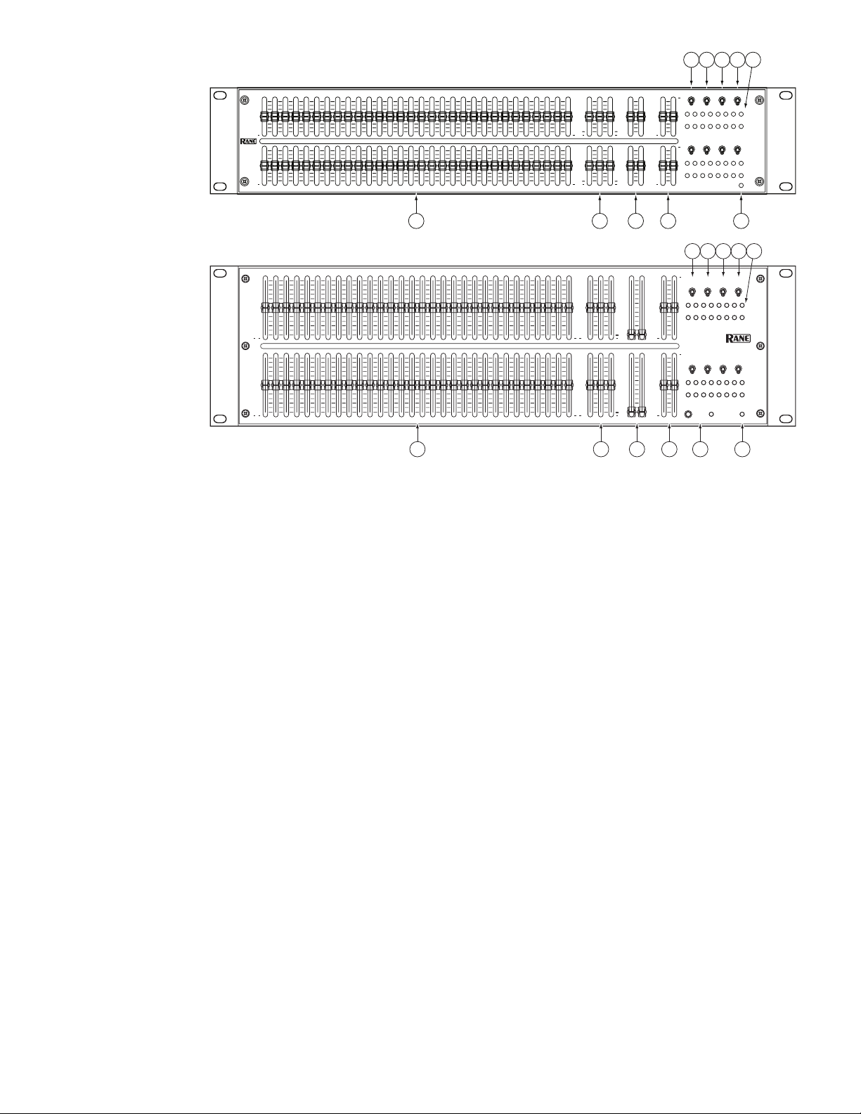
1 Graphic EQ controls: irty bands are provided for each channel. Each EQ slider has a resolution of 256 steps. e center detent position
guarantees a flat response. Slide control travel is 25mm (DEQ 60) or 45mm (DEQ 60L) with easy-to-read soft-touch handles.
2 LOW, MID, and HIGH TONE controls: Independent, Accelerated-slope™, 3-band TONE controls allow easy, intuitive adjustment of tone
response without the hassle of adjusting 30 bands. e TONE controls use 12 dB per octave Linkwitz-Riley filters. e Low/Mid crossover
point is 300 Hz. e Mid/High crossover point is 4 kHz. As with the EQ sliders, center detent provides a guaranteed flat response. e range of
control is +6 dB to off. Control resolution is 256 steps.
3 LOW CUT and HIGH CUT FILTERS: e LOW Cut Filter is adjustable over four octaves in 64 steps with a frequency range of 15 Hz to
240 Hz. e HIGH Cut Filter is adjustable over two octaves in 64 steps from 5 kHz to 20 kHz.
4 LEVEL controls serve two purposes, when used with the Meters (9):
1) Adjust the INPUT signal level to 0 dBu for good headroom and signal to noise.
2) Compensate for changes in signal level due to filter boost/cut settings by adjusting the OUTPUT signal level to 0 dBu.
e operation of the OUTPUT LEVEL control is reversed. Pushing the control up reduces gain. Pushing the control down increases the gain.
is allows the user to easily adjust sensitivity without affecting the output signal level. Simply grasp both input and output controls and move
together. e ranges of both controls is ±12 dB with a resolution of 256 steps.
5 BYPASS switches have two possible modes of operation. If the rear panel switch is set to BYPASS ALL, all filters and level controls are by-
passed. If the rear panel switch is set to BYPASS FILTERS, only the filters are bypassed. Filters include EQ, TONE and CUT. Automatic relay
bypass hardwires Inputs to Outputs in the event of a power failure.
6 A / B switches determine which set of controls is used by the A-channel or B-channel. Controls affected by the A / B switch are EQ, TONE,
CUT FILTERS, LEVEL, Q switches and ±12 / ±6 dB switches. Bypass switches are not affected.
7 PE R FECT- Q™: What you see is what you get. PROPORTional-Q: Classic smooth response. Most users will prefer the PERFECT-Q position.
Some users may prefer the PROPORT-Q setting. See Graphic EQ Controls on page Manual-4.
8 ±12 / ±6 dB switch changes the boost / cut of the Graphic EQ (1) for each channel. Use the ±6 dB unless you really need ±12 dB, the resolu-
tion is better.
9 Input and Output Meters are peak responding and indicate the signal level in dBu. Peak-dBu is held and displayed for 1.5 seconds. Attack is
instantaneous. Decay is 500 ms for a 20 dB step.
0 When the POWER indicator is on, it indicates that power is turned on. is works with 4 on the Rear Panel (next page).
q DEQ 60L CUT-ON LY mode switch: when pressed in, as shown by the LED, sets the range of the DEQ 60L EQ sliders 0 to -12 dB (gray num-
ber scale). When the switch is actuated, the DEQ 60L output audio is muted and slowly increased to prevent volume surprises.
Manual-2
Page 5

REAR PANEL DESCRIPTION
WIRING
TIP / PIN 2 = POSITIVE
RING / PIN 3 = NEGATIVE
SLEEVE = SIGNAL GROUND
PIN 1 = CHASSIS GROUND
+
-
+
-
This device complies with Part 15 of the FCC Rules. Operation is
subject to the following two conditions: (1) this device may not cause
harmful interference, and (2) this device must accept any interference
received, including interference that may cause undesired operation.
DEQ 60
MADE IN U.S.A.
RANE CORP.
ACN 001 345 482
U.S. PATENT 7,266,205
100-240V
50/60 Hz 20 WATTS
FOR CONTINUED
GROUNDING
PROTECTION
DO NOT REMOVE
SCREW
OUTPUT B
BYPASS
OUTPUT A INPUT B INPUT A
+
-
+
-
COMMERCIAL AUDIO
EQUIPMENT 24TJ
FILTERSALL
R
+
-
+
-
+
-
+
-
4 3 2 1
The DEQ 60 and DEQ 60L rear panels are identical except in height.
1 Channel A and B INPUTS: Plug the outputs of the mixer or other source to these Inputs. Choose between the XLR, the ¼" TRS, or the Eurob-
lock Input jack—use only one—they do not sum.
Rane adheres to the international and U.S. standard for balanced pin configurations: Pin 1 is chassis ground (neutral), pin 2 is hot (positive),
and pin 3 is signal return (negative).
Avoid the temptation to use unbalanced tip-sleeve ¼" TS plugs, but if you must, keep them short as possible, 10 feet (3 meters) maximum. Long
unbalanced cables invite hum, noise and other undesirables. Balanced TRS ¼" are much better at rejecting noise.
e Euroblocks normally connect the cable shield to the ground terminal. For those installations where the internal shield-to-chassis connection causes interference, connect each shield directly to the chassis grounding screw located above each Euroblock connector, keeping the shield
wrapped around the audio conductors as much as possible. For optimum Electromagnetic Interference (EMI) immunity, connect the shields at
both ends of the cable to chassis ground.
See the RaneNote “Sound System Interconnection” for more information on system connections and proper grounding practices.
2 Channel A and B OUTPUTS: Any Output can be used simultaneously with the others, take your pick. Same wiring as above...keep cables
short, always wire balanced when possible, eat your vegetables, yadda yadda.
3 BYPASS mode switch: See 5, Front Panel, previous page.
4 Power connector: Uses the standard cord provided. Inside the DEQ 60 is a universal internal switching power supply that accepts 100 to 240
VAC at 50 to 60 Hz, allowing it to work in most countries.
Manual-3
Page 6

Feature
1) Perfect-Q™ : What you see is what you get
Benefit
1) No EQ filter interaction. Response matches slider settings.
2) Proportional-Q: Classic smooth response
3) Independent Accelerated-slope™ 3-band tone controls
4) Low-cut and High-cut filters
5) Input and Output level controls
6) Eight segment metering for each input and output
7) Two Boost / Cut ranges: ± 6 dB or ± 12 dB
8) Each audio channel may use A or B controls
9) Analog controls
10) XLR, TRS and Euroblock Phoenix connectors
11) Bypass switch (DSP)
12) Bypass relay (power failure)
13) Exceptional RF and Magnetic immunity
14) Universal switching power supply
2) Familiar response. Smooth tone contouring.
3) Adjust Tone response without moving a dozen EQ sliders.
4) Band limit for application: Voice, Music, Headphones, etc.
5) Optimize dynamic range. Match level after EQ.
6) Allows accurate use of level controls.
7) Select control resolution and range for the application.
8) Stereo Linking; Two “analog memories”; A-curve / B-curve comparison.
9) Quick control access with one control, one function, no confusion.
10) Connector matches your cables.
11) EQ in/out compare. Bypass Filters only or bypass Filters and Level controls.
12) No pops on turn-on or turn-off. Passes signal when power is off.
13) Works in high RF environments. Works next to power amps.
14) Works virtually anywhere in the world.
15) DEQ 60L: Cut-Only mode
Graphic EQ Controls
Control each of the thirty bands of EQ with high resolution, 256
step slide controls. e center detent position guarantees a flat
response. Perfect-Q™ filters guarantee accurate graphic response
and no band interaction.
e elimination of band interaction means the DEQ filters
are suitable for “ringing out a room” and capable of the very
subtle adjustments required by the most demanding user. Unlike
previous designs that act upon a bandwidth of up to one octave
when cut 12 dB, Perfect-Q only affects the intended 1/3 octave.
For the first time, the user is able to adjust a single 1/3 octave
band with no affect on adjacent bands. e lack of band interaction guarantees slider settings accurately indicate frequency
response.
For full details and comparisons to previous EQs, see
“Perfect-Q: e Next Step in EQ Design” included with this
manual.
15) Maximum level of precision.
Control Surface
All graphics are screened on the reverse side of a durable Lexan
surface. e graphics remain clear even after years of life on the
road.
Universal Switching Power Supply
e DEQ 60 or DEQ 60L operates on any AC mains from 100
VAC to 240 VAC, 50 Hz or 60 Hz. e line cord attaches to a
standard IEC appliance inlet, shipped with each unit.
Security
e DEQ 60 model includes a 3.5" security cover in the box. An
optional 5.2" security cover is available as an accessory for the
DEQ 60L.
©Rane Corporation 10802 47th Ave. W., Mukilteo WA 98275-5098 USA TEL 425-355-6000 FAX 425-347-7757 WEB www.rane.com
Manual-4
106692
 Loading...