

Page 1
DATA SHEET
DC 24
THRESHOLD THRESHOLDRATIO THRESHOLD RATIO SIG LEVEL OL
BYPASS
MODE
FREQUENCY
POWER
COMPRESSOR CH 1 OUTPUTLIMITER CROSSOVER
GAIN
REDUCTION
THRESHOLD THRESHOLDRATIO THRESHOLD RATIO SIG LEVEL OL
BYPASS
GATE / EXPANDERGATE / EXPANDER COMPRESSOR CH 2 OUTPUTLIMITER
GAIN
REDUCTION
LOW
(:1) (:1)
SLAVE
DUAL
DYNAMIC
CONTROLLER
-50 10
-40
2
-30
-20
3
-10
1 1
01 10
8
64
7
5
1.1
4
1.2
1.4
1.6
2
3
-6
24
12
+6
0
6
3
-40
-30
-20
10
0
+12-12
+6-6
0
HIGH
(:1) (:1)
24
12
6
3
0
7k
200
70
100
75
90
150
125
400
2k
800
1.2k
+20-20
-6 +6
0
+20-20
-6 +6
0
+12-12
-10
20-48
2
3
1 1
0
8
64
7
5
-50 10
-40
-30
-20
0
-10
(:1)
1 1
0
1.1
4
1.2
1.4
1.6
2
3
-40
-30
-20
0
10
-10
20-48
6k
4k
0
0
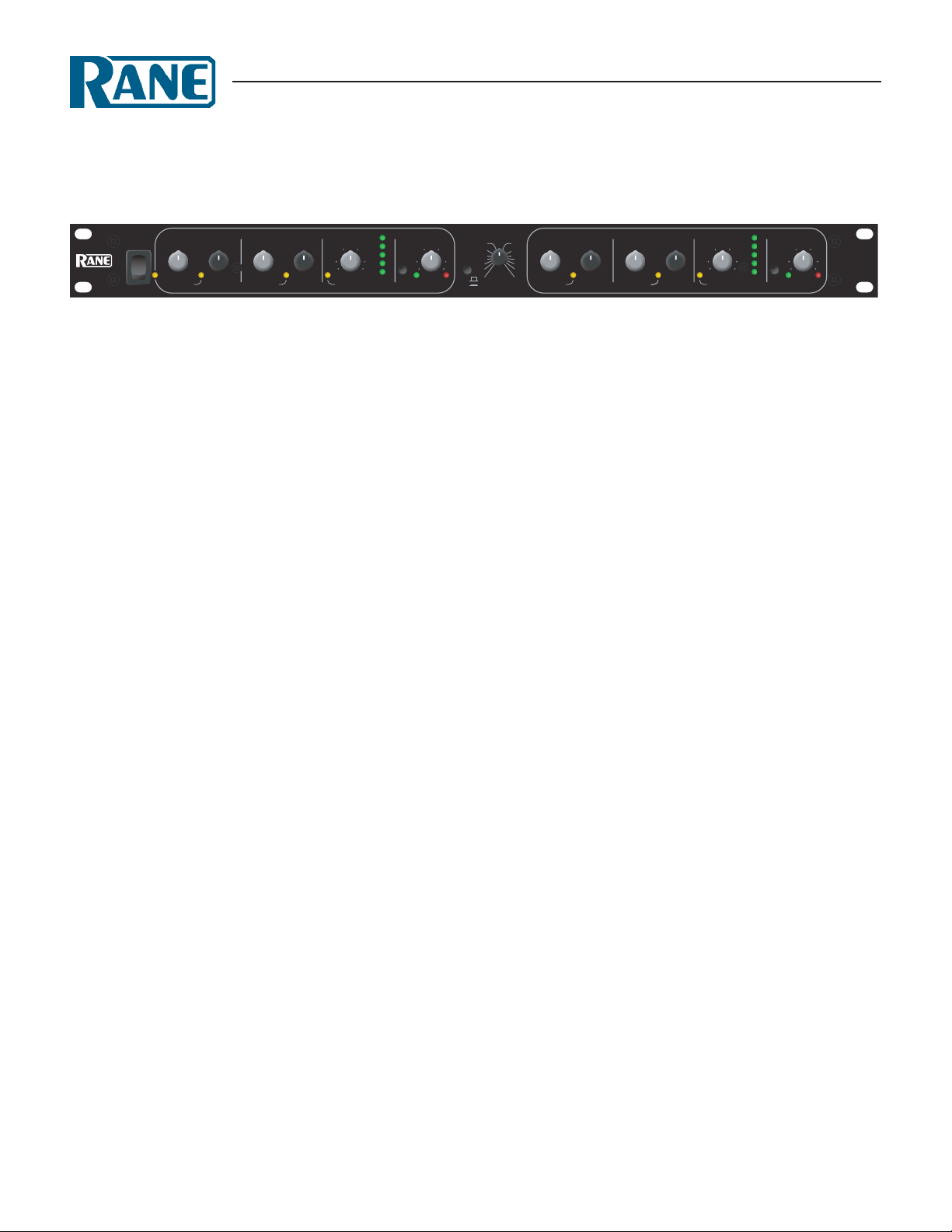
General Description
e Rane Model DC 24 Dynamic Controller is a two channel Compressor, Limiter, Expander Gate system with very unusual attributes. e DC 24 offers unprecedented control of its
operating parameters as well as a built-in 24 dB/octave LinkwitzRiley Crossover which gives it very impressive capabilities.
Total freedom from control interaction highlight the DC 24
as well as the availability of separate Compressor and Limiter
controls. e Compressor offers control over both Ratio and
reshold, while the Limiter allows setting a separate reshold.
In doing this, the DC 24 allows the operator to create a smooth
transition between subtle compression over a wide dynamic
range and peak-stop limiting at the sound system’s highest allowable level. If that’s not enough, the DC 24 also offers independent Expander/Gate Ratio and reshold controls. is third
level of signal manipulation makes the DC 24 a most useful and
revolutionary device.
DC 24
DYNAMIC CONTROLLER
Attack and release times are automatic and program depen
dent. is simplifies use of the DC 24, as these subtle controls
can confuse most users. History has proven that experienced
compressor users rarely miss these controls after using a DC 24.
e internal Crossover allows the DC 24 to operate as a
two-way speaker dividing network along with all of the dynamic characteristics of a fully featured Compressor Limiter. In
addition to this application, the DC 24 supplies the necessary
circuitry to allow the unit to divide a single channel of audio
information in two separate frequency ranges and to then recombine the program material into one Channel. Using the DC
24 in this way eliminates the pumping and breathing associated
with compression and limiting when only one Channel is used to
cover the entire audio spectrum.
Refer to “e DC 24 User’s Guide,” on the Rane website, for
an easy-to-understand guide of operation and applications.
-
Features
• Ratio & Threshold Controls for Compressor and Gate/Expander
• Limiter Threshold Controls
• Program Dependent Attack & Release
• Linkwitz-Riley Crossover with 24 dB per Octave Slopes
• Low-High Crossover Mode (1 In/2 Out)
• Bandsplit Combine Mode (1 In/1 Out)
• Stereo/Dual Modes (2 In/2 Out)
• Side Chain Insert Jacks
• Balanced XLR & ¼" TRS Connectors
• -10 dBV / +4 dBu Gain Switch
• UL/CSA Remote Power Supply (120 VAC)
• CE (Low Voltage & EMC) Remote Power Supply (230 VAC)
Data Sheet-1
Page 2
DC 24
DYNAMIC CONTROLLER
Parameter Specification Limit Units Conditions/Comments
Compressor
..........reshold Range -50 to +20
..........Ratio Range 1:1 to 10:1 10
Expander / Gate
..........reshold Range -50 to +10 5 dB
..........Ratio Range 1:1 to 20:1 10
Limiter
..........reshold Range -20 to +20
Crossover
..........Type Linkwitz-Riley 4th-order 24 dB per octave slopes
..........Range 70 Hz to 7 kHz
Inputs: Type Active Balanced / Unbalanced
..........Connectors XLR & + ¼" TRS
..........Impedance 20k 1%
..........Maximum Level +20 1 dBu
Outputs: Type Active Balanced
..........Connectors XLR & + ¼" TRS
..........Impedance 100 1%
..........Maximum Level +26
+20 1 dBu 600 Ω or greater
Overall Gain Range -12 to +12 ±1 dB Center detent unity gain
RFI Filters Yes
Passive Bypass Switch Yes
LED resholds: Overload +22
..........Signal Present -40
Frequency Response 20 Hz to 20 kHz +0/-.5 dB
THD+Noise 0.05 .01 % +4 dBu, 1 kHz
IM Distortion (SMPTE) 0.1 .01
Signal-to-Noise Ratio 108 2 dB Unity Gain re +20 dBu, 20 kHz BW
92
Unit: Agency Listing
..........120 VAC model Class 2 Equipment National Electrical Code
UL & CSA Exempt Class 2 equipment
..........230 VAC model CE-EMC EMC directive 89/336/EEC
CE-Safety Exempt per art. 1, LVD 73/23/EEC
Power Supply: Agency Listing Rane model RS 1 Class 2 Equipment
..........120 VAC model UL File no. E88261
CSA File no. LR58948
..........230 VAC model CE-EMC EMC directive 89/336/EEC
CE-Safety LV directive 73/23/EEC
..........100 VAC model Built to JIS Japan only
Power Supply Requirement 18 VAC w/center tap 0.1 Vrms
Maximum Current 600 mA RMS current from remote supply
Unit: Construction All Steel
..........Size 1.75"H x 19"W x 5.3"D (1U) (4.4 cm x 48.3 cm x 13.5 cm)
..........Weight 5 lb (2.3 kg)
Shipping: Size 4.5" x 20.3" x 13.75" (11.5 cm x 52 cm x 35 cm)
..........Weight 9 lb (4.1 kg)
Note 1: 0 dBu=0.775 Vrms
Note 2: Unless otherwise stated, all measurements made with resholds set at maximum, Ratios set at minimum.
Data Sheet-2
5 dB
%
%
2 dB
5 % 41-detent continuously variable pot
Ω
Ω Each output
1 dBu 2 kΩ or greater
1 dBu Output or any internal level
3 dBu Input Level
% 60 Hz / 7 kHz, 4:1, +4 dBu
2 dB Unity Gain re +4 dBu, 20 kHz BW
Page 3

Block Diagram
+
+
+
+ +
2
FILTER
RFI
RFI
FILTER
2
HIGH PASS
LOW PASS
FREQ
CROSSOVER
CROSSOVER
NORMA
L
CHAI
N
COMPRESSO
R
CONTRO
L
CONTRO
L
GATE
CONTRO
L
VC
A
IN OUT
SIDE
OUTPUT LEVE
L
-12 TO +12 dB
OUTIN
VCA
SIDE
GATE
CONTRO
L
CONTRO
L
COMPRESSO
R
CHAI
N
CONTRO
L
DUAL
SLA
VE
COMBIN
E
SEPARAT
E
MODE
OUTPUTS
2
2
CH 2
/
HIGH OUT
CH 1
/
LOW OUT
CH 1
/
CROSSOVER
IN
CH2 IN
LIMITER
CONTRO
L
CONTRO
L
LIMITER
BYPASS
TRI
M
GAIN
-10 dB
V+4 dBu
+
+
+
+
+4 dBu -10 dB
V
TRI
M
GAIN
OUTPUT LEVE
L
-12 TO +12 dB
BYPASS
DC 24
DYNAMIC CONTROLLER
Architectural Specifications
e dynamic processor shall be a two (2) channel unit, each
channel of which provides independent control over its gating,
compression and limiting functions. e gating function shall
provide a means for setting the gate threshold as well as the ratio
of the function thus providing a means for gentler slopes to occur such as one would expect to find in an expander.
e compressor shall also provide a means for setting threshold and ratio independently. e limiter shall also provide a
means for setting its operational threshold, but shall differ from
the other two functions in that limit ratio shall be a function of
limit level.
All attack and release characteristics provided by the dynamic controller shall be a function of the current program material,
thus providing a high level of transparency to the listener.
e dynamic processor shall provide an active crossover
circuit for the purpose of using the unit to drive amplifiers connected to two-way loudspeaker systems as well as for dividing a
single channel audio source into two frequency bands for ulti-
mate recombination at the outupts of the device. e crossover
shall be a fourth-order Linkwitz-Riley type configuration.
Passive bypass switches shall be provided to ensure total
bypass of the unit’s active circuitry in the event of power failure.
e inputs and outputs shall be active balanced/unbalanced
designs terminated with XLR & ¼" TRS connectors. e sidechain send and receive connectors shall be ¼" unbalanced types,
wired tip=send, ring=return.
RFI filters shall be provided at the processor’s inputs. LEDs
shall be provided to indicate the presence of an input signal as
well as high level overload conditions.
e unit shall be exempt from agency safety requirements
and powered from a UL listed / CSA certified remote power supply (120 VAC), or CE approved (230 VAC) via a rear panel input
modular plug.e unit shall be entirely constructed from coldrolled steel, and mount into a standard EIA relay rack occupying
1 rack space.
e unit shall be a Rane Corporation Model DC 24.
Data Sheet-3
Page 4

DC 24
OUTPUTS CH 2 TRIM
CH 2 HIGH /
COMBINE OUT
CH 2
IN
CROSSOVER
ENGAGE
CLASS 2 EQUIPMENT
CH 1 /
CROSSOVER IN
CH 1 /
LOW OUT
DC 24
+4 dBu
COMBINESEPARATE
-10 dBV
TIP=SEND
RING=RETURN
TIP=SEND
RING=RETURN
INPUTS AND OUTPUTS
TIP=#2=POSITIVE
RING=#3=NEGATIVE
SLEEVE=#1=SIGNAL GROUND
CH 1
SIDE CHAIN
CH 2
SIDE CHAIN
MADE IN U.S.A.
RANE CORP.
N108
+4 dBu-10 dBV
CH 1 TRIM
600mA
POWER
DYNAMIC CONTROLLER
Rear Panel
Application Information
Traditionally, a product such as the DC 24 has been referred
to as a “Compressor / Limiter” because the range of the Ratio
control on the Compressor has been wide enough to accommodate both gentle compression and harder limiting effects. Not,
however, simultaneously. One had to make a choice between the
two modes of operation. On some models a Gate has been provided which may or may not be part of the Compressor function.
In the DC 24, all three functions of each channel are independent. Gating may occur when low-level signals are present,
compression may occur when the level increases, and “peak-stop”
limiting is available for high-level signals. is provides a three
slope capability which is rather unique in the audio industry.
Additionally, the DC 24 can help out a great deal on the low
end of the amplitude spectrum by serving as a noise gate simultaneously. e Compressor may be used to “tighten” vocals and
instrumentals while leaving the Limiter function available for use
as a safety valve.
To accomplish this feat, the DC 24 provides three separate
“Side Chains” in each Channel, each having its own set of front
panel controls. For the Gate / Expander function, input signal
is converted from an audio format to a control signal and applied to the threshold circuit. If the output of the controller is
below the specified threshold, it is passed along to the Gate /
Expander Ratio control. e Ratio control allows attenuation of
the controller to inhibit the slope of the Expander. After this attenuation, the control signal is delivered to the Channel’s control
summing amplifier where it will meet similar signals generated
by the Compressor control system.
e Compressor controller works remarkably similarly to the
Gate, the exception being the polarity. While the Gate circuit
reduces gain when input level decreases below reshold, the
Compressor decreases gain when input increases above reshold. e Compressor also receives the output of the controller,
applies it to its threshold determinator, and passes the signal
to the ratio attenuator if threshold conditions are satisfied. e
output of the Ratio control is applied to the summing amplifier
referenced in the gate section.
Side Chain inserts have been provided on the rear of the unit
to allow the insertion of an equalizer into the control circuits
of the Gate and the Compressor. is will allow the user to
create a frequency-dependent threshold for the Gate and/or the
Compressor. is feature is useful when attempting to control
sibilance in vocals.
e Limiter operates in an entirely different manner than the
preceding sections. e control circuit for the Limiter monitors
the output of the VCA, not the input of the unit. Anytime the
output of the VCA exceeds the reshold set on the front panel,
Limiting begins to take place. e ratio of the Limiter is set
automatically and is a function of the excess level the system is
attempting to deliver above the preset reshold. e attack and
release time of the Limiter is a function of the speed at which the
input signal is attempting to drive the output of the unit above
the reshold level.
e Crossover function of the DC 24 is based on Rane’s
time-proven 4th-order state-variable Linkwitz-Riley design. is
yields a 24 dB per octave slope and an in-phase characteristic.
Since the outputs are in phase with each other, they recombine
properly when the channel summing mode is selected via the
rear panel Separate/Combine switch.
In its band-split mode, the DC 24 allows separate processing
of low frequencies and high frequencies; a mode which makes its
operation all the more transparent. When the Crossover is used
in conjunction with a two-way loudspeaker system, adequate
driver protection may be ensured while providing a very flexible
means of program manipulation.
For a better view of the various operational modes, refer to
“e DC 24 Users Guide” RaneNote, from the Rane website.
Available Accessories
• SC 1.7 Security Cover
©Rane Corporati on 10802 47th Ave. W., Mukil teo WA 982 75-50 98 TEL 425-3 55-6000 FAX 425 -347- 7757 WEB www.rane.com
Data Sheet-4
All features & specifications subject to change without notice.DOC 107501
 Loading...