

Page 1
SLAVE THRESHOLD
OL+4
MASTERREDUCTION
GAIN
THRESHOLD RATIO BYPASSLEVEL
OL+4
LEVEL
GATEINPUT COMPRESSOR
LINK
OUTPUT
LEVEL
6
24
12
3
THRESHOLD REDUCTION
GAIN
THRESHOLD RATIO BYPASS
GATE COMPRESSOR OUTPUT
LEVEL
6
24
12
3
1
INPUT
POWER
2
DC 22S
DYNAMIC
CONTROLLER
dBu dBu
:1
dB
-20
-60
-80
-70
-50
-40
-30
0
10
20-40
-30
-10
-20
31.7
1
1.2 10
2
6-6
12
15-15
-12
0
dBu dBu
:1
dB
-20
-60
-80
-70
-50
-40
-30
0
10
20-40
-30
-10
-20
31.7
1
1.2 10
2
6-6
12
15-15
-12
0
DC 22S
DYNAMICS CONTROLLER
Page 2
RISK OF ELECTRIC SHOCK
DO NOT OPEN
CAUTION
IMPORTANT SAFETY INSTRUCTIONS
1. Read these instructions.
2. Keep these instructions.
3. Heed all warnings.
4. Follow all instructions.
5. Do not use this apparatus near water.
6. Clean only with a dry cloth.
7. Do not block any ventilation openings. Install in accordance with manufacturer’s instructions.
8. Do not install near any heat sources such as radiators, registers, stoves, or other apparatus (including ampliers) that produce heat.
9. Do not defeat the safety purpose of the polarized or grounding-type plug. A polarized plug has two blades with one wider than the other. A grounding-type plug has two blades and a third grounding prong. e wide blade or third prong is provided for your safety. If the provided plug does not
t into your outlet, consult an electrician for replacement of the obsolete outlet.
10. Protect the power cord and plug from being walked on or pinched particularly at plugs, convenience receptacles, and the point where it exits from
the apparatus.
11. Only use attachments and accessories specied by Rane.
12. Use only with the cart, stand, tripod, bracket, or table specied by the manufacturer, or sold with the apparatus. When a cart is used, use caution
when moving the cart/apparatus combination to avoid injury from tip-over.
13. Unplug this apparatus during lightning storms or when unused for long periods of time.
14. Refer all servicing to qualied service personnel. Servicing is required when the apparatus has been damaged in any way, such as power supply
cord or plug is damaged, liquid has been spilled or objects have fallen into the apparatus, the apparatus has been exposed to rain or moisture, does
not operate normally, or has been dropped.
15. e plug on the power cord is the AC mains disconnect device and must remain readily operable. To completely disconnect this apparatus from
the AC mains, disconnect the power supply cord plug from the AC receptacle.
16. is apparatus shall be connected to a mains socket outlet with a protective earthing connection.
17. When permanently connected, an all-pole mains switch with a contact separation of at least 3 mm in each pole shall be incorporated in the electrical installation of the building.
18. If rackmounting, provide adequate ventilation. Equipment may be located above or below this apparatus, but some equipment (like large power
ampliers) may cause an unacceptable amount of hum or may generate too much heat and degrade the performance of this apparatus.
19. is apparatus may be installed in an industry standard equipment rack. Use screws through all mounting holes to provide the best support.
WARNING: To reduce the risk of re or electric shock, do not expose this apparatus to rain or moisture. Apparatus shall not be exposed to dripping
or splashing and no objects lled with liquids, such as vases, shall be placed on the apparatus.
NOTE: is equipment has been tested and found to comply with the limits for a Class B digital device, pursuant to part 15 of the FCC Rules. ese
limits are designed to provide reasonable protection against harmful interference in a residential installation. is equipment generates, uses and can
radiate radio frequency energy and, if not installed and used in accordance with the instructions, may cause harmful interference to radio communications. However, there is no guarantee that interference will not occur in a particular installation. If this equipment does cause harmful interference to
radio or television reception, which can be determined by turning the equipment o and on, the user is encouraged to try to correct the interference
by one or more of the following measures:
• Reorient or relocate the receiving antenna.
• Increase the separation between the equipment and receiver.
• Connect the equipment into an outlet on a circuit dierent from that to which the receiver is connected.
• Consult the dealer or an experienced radio/TV technician for help.
CAU TIO N: Changes or modications not expressly approved by Rane Corporation could void the user's authority to operate the equipment.
is Class B digital apparatus complies with Canadian ICES-003.
Cet appareil numérique de la classe B est conforme à la norme NMB-003 du Canada.
WARNING
To reduce the risk of electrical shock, do not open the unit. No user
serviceable parts inside. Refer servicing to qualied service personnel.
e symbols shown below are internationally accepted symbols that warn
of potential hazards with electrical products.
is symbol indicates that a dangerous voltage
constituting a risk of electric shock is present within
this unit.
is symbol indicates that there are important
operating and maintenance instructions in the
literature accompanying this unit.
Page 3
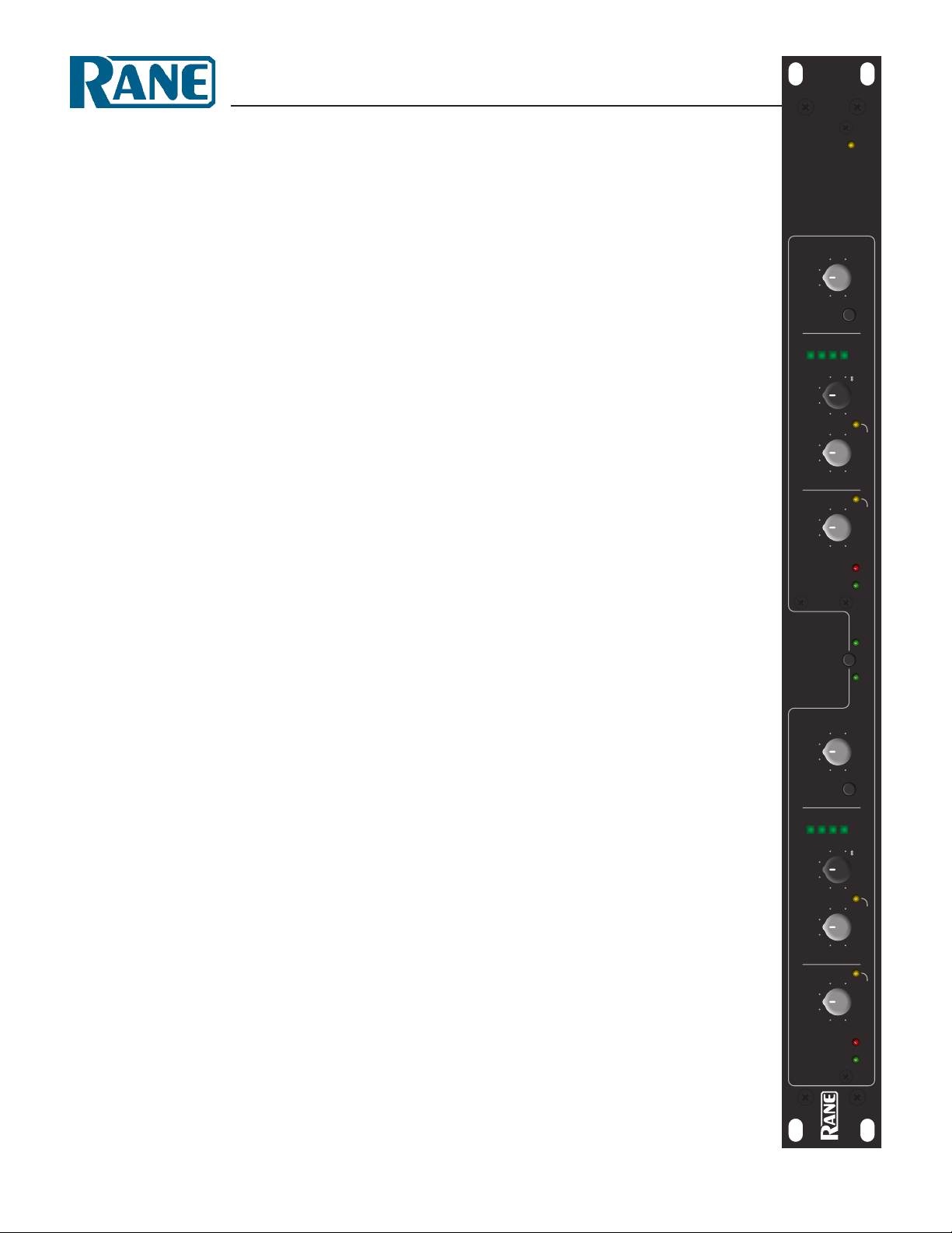
OPERATORS MANUAL
SLAVE THRESHOLD
OL+4
MASTERREDUCTION
GAIN
THRESHOLD RATIO BYPASSLEVEL
OL+4
LEVEL
GATEINPUT COMPRESSOR
LINK
OUTPUT
LEVEL
6
24
12
3
THRESHOLD REDUCTION
GAIN
THRESHOLD RATIO BYPASS
GATE COMPRESSOR OUTPUT
LEVEL
6
24
12
3
1
INPUT
POWER
2
DC 22S
DYNAMIC
CONTROLLER
dBu dBu
:1
dB
-20
-60
-80
-70
-50
-40
-30
0
10
20-40
-30
-10
-20
31.7
1
1.2 10
2
6-6
12
15-15
-12
0
dBu dBu
:1
dB
-20
-60
-80
-70
-50
-40
-30
0
10
20-40
-30
-10
-20
31.7
1
1.2 10
2
6-6
12
15-15
-12
0
QUICK START
Shredded, this document makes excellent packing material. In
its present form, it makes interesting and useful reading. If you
run out of patience quickly, at least read this part to make sure
you don’t exterminate everything within a two mile radius by
doing something wrong.
First, be sure the POWER switch is off. Attach one or two
channels of Inputs and Outputs to the respective connectors on
the rear. is device uses low impedance balanced line drivers. Do
not connect the XLR “+” or “–” output pins to ground, as this may
cause the power supply to shut down. For unbalanced use, leave the
unused output pin (“+” or “–”) unterminated. OK, now you can
power up your sound system, volumes down, amp turned on last.
With the GATE THRESHOLD turned all the way down to
-80 dBu, COMPRESSOR THRESHOLD turned all the way
up to 20 dBu, COMPRESSOR RATIO turned all the way
down to 1, and the OUTPUT LEVEL control in the center at 0
dB, you have an expensive patch cord.
While sending a signal to the DC 22S, adjust the output
level of the previous device so the +4 dBu LED lights occasionally, but the OL LED does not light. If you are driving the ¼"
DC 22S
STEREO COMPRESSOR
INPUTS with a balanced signal (tip-ring-sleeve), set the Input
Gain switch to +4 dBu (in). When driving this input with an
unbalanced signal (tip-sleeve), set this switch to –10 dBv (out).
Regardless of the type of Input, you might need to set this switch
so the INPUT LEVEL LEDs light correctly.
Now increase the COMPRESSOR RATIO to something
useful, like 2:1 (with the control set at 2, the Ratio is 2:1; at 5, it
is 5:1.) Adjust the COMPRESSOR THRESHOLD to the point
you want the Compressor to kick in. e GAIN REDUCTION
meter reads the amount of signal compression.
If you want the quiet parts to be even quieter, increase the
GATE THRESHOLD so only higher levels make it through the
Gate.
Both Gates and Compressors will activate by the source
material applied to either channel if the LINK switch is on. is
is the preferred setting for stereo program material. e channel 1 controls set both channels to the same adjustments, as the
channel 2 controls go dormant and the LEDs extinguish. If
the LINK switch is off, then both channels are independently
controllable.
WEAR PARTS: is product contains no wear parts.
Manual-1
Page 4

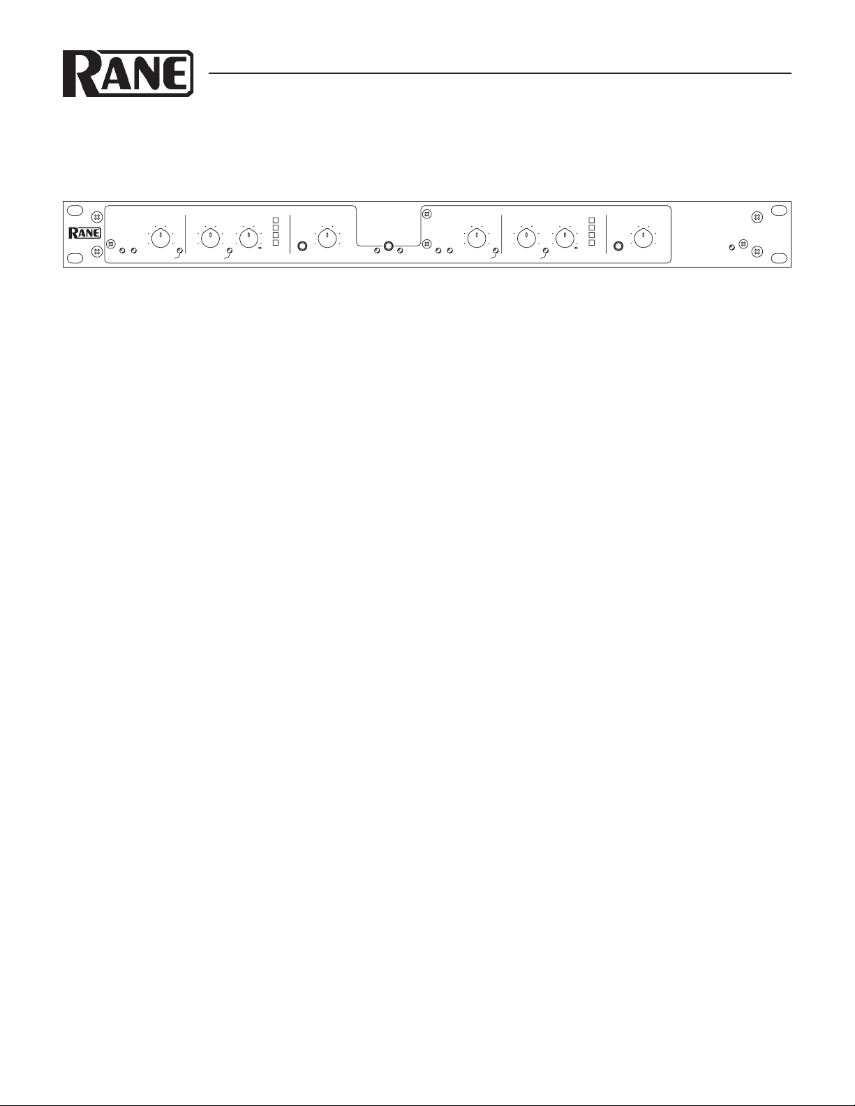
Front Panel Description
SLAVE THRESHOLD
OL+4
LEVEL
LINK
THRESHOLD REDUCTION
GAIN
THRESHOLD RATIO BYPASS
GATE COMPRESSOR OUTPUT
LEVEL
6
24
12
3
INPUT
POWER
2
DC 22S
DYNAMIC
CONTROLLER
dBu dBu
:1
dB
-20
-60
-80
-70
-50
-40
-30
0
10
20-40
-30
-10
-20
31.7
1
1.2 10
2
6-6
12
15-15
-12
0
OL+4
MASTERREDUCTION
GAIN
THRESHOLD RATIO BYPASSLEVEL
GATEINPUT COMPRESSOR
LINK
OUTPUT
LEVEL
6
24
12
3
1
dBu dBu
:1
dB
-20
-60
-80
-70
-50
-40
-30
0
10
20-40
-30
-10
-20
31.7
1
1.2 10
2
6-6
12
15-15
-12
0
SLAVE THRESHOLD
MASTERREDUCTION
GAIN
THRESHOLD RATIO BYPASSLEVEL
OL+4
LEVEL
LINK
OUTPUT
LEVEL
6
24
12
3
THRESHOLD REDUCTION
GATE COMPRESSOR OUTPUT
INPUT
2
:1
dB
-20
-40
-30
0
10
20-40
-30
-10
-20
31.7
1
1.2 10
2
6-6
12
15-15
-12
0
dBu dBu
-20
-60
-80
-70
-50
-40
-30
SLAVE THRESHOLD
MASTERREDUCTION
OL+4
LEVEL
LINK
OUTPUT
LEVEL
THRESHOLD REDUCTION
GAIN
THRESHOLD RATIO BYPASS
GATE COMPRESSOR OUTPUT
6
24
12
3
INPUT
2
dB
6-6
12
15-15
-12
0
dBu dBu
:1
-20
-60
-80
-70
-50
-40
-30
0
10
20-40
-30
-10
-20
31.7
1
1.2 10
2
INPUT LEVEL indicators: With signal applied, the +4 dBu
LED may light occasionally. If the OL (overload) LED flashes,
turn the output level down on the previous device.
GATE THRESHOLD control sets the point at which the Input
signal level causes the Gate to become active.
_____________________________________________
COMPRESSOR THRESHOLD control sets the point at
which the Input signal level causes the Compressor to become
active. See Figure 1 on page Manual-4.
COMPRESSOR RATIO control: Once the reshold is
exceeded, the Ratio of input change to output change is determined by this control. e compressor has no effect when set
at 1:1. But at 10:1, it takes a 10 dB input signal increase above
the reshold to produce a 1 dB increase in Output Gain. See
Figure 2 on page Manual-4.
GAIN REDUCTION LEDs show the amount of average signal
reduction in dB. is aids in setting the THRESHOLD and
RATIO controls by showing how much compression is occuring.
_____________________________________________
BYPASS switch compares the compressed and non-compressed
signal. ere is one for each channel. e INPUT LEVEL
indicators remain active regardless of switch position.
OUTPUT LEVEL control increases or decreases the output
gain of each Channel by 15 dB. In the center detent, gain will
be unity.
LINK switch activates both Compressors when either channel’s
signal exceeds the set reshold, preserving stereo imaging.
Switch this ON when using stereo material. e channel 1
controls become the Master when this switch is active, rendering the channel 2 controls and indicators dead.
_____________________________________________
Channel 2 controls duplicate the controls in channel 1. ese
are not active if the LINK switch is engaged.
Manual-2
When the POWER LED is lit, the DC 22S is connected to a
100-240 VAC source and ready to rock.
Page 5

Rear Panel Description
DC 22S STEREO COMPRESSOR
TTM 56S MIXER
AC 22S STEREO 2-WAY CROSSOVER
ME 15S STEREO EQUALIZER
OUTPUTSINPUTS
RIGHTLEFT
OUTPUTS
LEFT
INPUTS
RIGHT
LEFTRIGHT
RIGHTLEFT
LEVELLEVEL
010010
LEVELLEVEL
010010
STEREO AMP, HIGH
MONO OR BRIDGED AMP, MONO SUB
RIGHT SPEAKER
LEFT SPEAKER
MONO SUBWOOFER
WIRING
TIP / PIN 2 = POSITIVE
RING / PIN 3 = NEGATIVE
SLEEVE = SIGNAL GROUND
PIN 1 = CHASSIS GROUND
CHANNEL 1
OUTPUT INPUT
CHANNEL 2
OUTPUT INPUT
MADE IN U.S.A.
RANE CORP.
ME 15S
ACN 001 345 482
COMMERCIAL AUDIO
EQUIPMENT 24TJ
R
100-240 V
50/60 Hz 7 WATTS
This device complies with Part 15 of
the FCC Rules. Operation is subject
to the following two conditions:
(1) this device may not cause
harmful interference, and (2) this
device must accept any interference
received, including interference that
may cause undesired operation.
ACN 001 345 482
INPUT
1
OUTPUT
1
BAL/UNBALBALANCEDBALANCED BAL/UNBAL
+4 dBu
-10 dBV
MADE IN U.S.A.
RANE CORP.
DC 22S
WIRING
3-PIN XLR:
• PIN 2 = (+), • PIN 3 = (–),
• PIN 1 = CHASSIS (SHIELD)
1/4" PHONE, BALANCED:
• TIP = (+), • RING = (–),
• SLEEVE = CHASSIS (SHIELD)
1/4" PHONE, UNBALANCED:
• SEE THE RANENOTE: SOUND
SYSTEM INTERCONNECTION
100-240 V
50/60 Hz 7 WATTS
COMMERCIAL AUDIO
EQUIPMENT 24TJ
R
This device complies with Part
15 of the FCC Rules. Operation
is subject to the following two
conditions: (1) this device may
not cause harmful interference,
and (2) this device must accept
any interference received,
including interference that may
cause undesired operation.
INPUT
2
OUTPUT
2
BAL/UNBALBALANCEDBALANCED BAL/UNBAL
+4 dBu
-10 dBV
ACN 001 345 482
LOW OUTCH 1 IN
3-WAY IN
MONO SUB OUTMONO
LOW OUT
HIGH OUT
STEREO 2-WAY
SUBWOOFER SWITCH MUST
BE SET TO 2-CHANNEL
FOR MONO 3-WAY
CH 2 INLOW OUT
2-CHANNEL
SUBWOOFER
MONO SUB
OMIT MONO
MONO 3-WAY
MODE
OMIT MONO
MONO SUB: OMIT
MID OUT
HIGH OUT
HIGH OUT
MADE IN U.S.A.
RANE CORP.
AC 22S
PIN 2: POSITIVE
PIN 3: NEGATIVE
PIN 1: CHASSIS GND
100-240 V
50/60 Hz 7 WATTS
COMMERCIAL AUDIO
EQUIPMENT 24TJ
R
This device complies with Part
15 of the FCC Rules. Operation
is subject to the following two
conditions: (1) this device may
not cause harmful
interference, and (2) this
device must accept any
interference received,
including interference that may
cause undesired operation.
AUX
PHONO
GROUNDS
POWER
PGM 1PGM 2
4321
4
4332211
4321
100-240V
50/60 Hz
20 WATTS
ACN 001 345 482
MADE IN U.S.A.
RANE CORP.
U.S. PATENT 6,813,361
OUTIN
OUTIN
MIC
BALANCED
MASTER
OUTPUTS
R
L
R
L
R
L
R
L
RLR
L
LINE
PHONO
TTM 56S
COMMERCIAL AUDIO
EQUIPMENT 24TJ
R
EFFECTS
SEND
UNBALANCED
FlexFX
RETURN
TIP = SEND
RING = RTN
BALANCED
WIRING
3-PIN XLR:
• PIN 2 = (+), • PIN 3 = (–),
• PIN 1 = CHASSIS (SHIELD)
1/4" PHONE, BALANCED:
• TIP = (+), • RING = (–),
• SLEEVE = CHASSIS (SHIELD)
1/4" PHONE, UNBALANCED:
• SEE THE RANENOTE: SOUND
SYSTEM INTERCONNECTION
This device complies with Part
15 of the FCC Rules. Operation
is subject to the following two
conditions: (1) this device may
not cause harmful interference,
and (2) this device must accept
any interference received,
including interference that may
cause undesired operation.
INPUT
2
OUTPUT
2
BAL/UNBALBALANCEDBALANCED BAL/UNBAL
+4 dBu
-10 dBV
INPUTS 1 and 2: Choose between the balanced XLR or the balanced/unbalanced ¼" TRS jacks, but only use one. Inserting a ¼"
TS jack will work—however—we recommend using balanced lines, especially when connecting any cable over 10 feet (3 meters)
in length. Consult the Sound System Interconnection RaneNote provided with this manual.
INPUTS 1 and 2 Gain Trim Switch: In its +4 dBu position, the Input gain of the respective channel is unity. In the -10 dBV posi-
tion, the input gain is increased by 12 dB (although mathematically suspicious, it really is 12 dB, not 14 dB) to compensate for
certain recording devices. is switch must be in the +4 dBu position for front panel calibration accuracy.
OUTPUTS 1 and 2 are delivered by the balanced XLR or the unbalanced ¼" TS jacks. Using both types of Outputs are permissible
to drive two devices, such as an amplifier and a recorder. is device uses low impedance balanced line drivers. Do not connect the
XLR “+” or “–” output pins to ground, as this may cause the power supply to shut down. For unbalanced use, leave the unused output pin
(“+” or “–”) unterminated.
System wiring example for a DJ system
Manual-3
Page 6

OPERATING INSTRUCTIONS
AUDIO PRECISION amp 09 AUG 101 14:51:28
-80
-70
-60
-50
-40
-30
-20
-10
0
AMPL(dBr) vs AMPL(dBu)
-80 -70 -60 -50 -40 -30 -20 -10 0
INPUT (dBu)
O
U
T
P
U
T
d
B
u
AUDIO PRECISION 09 AUG 101 14:34:57
-60
-50
-40
-30
-20
-10
0
10
20
-40
-30
-20
-10
0
10
AMPL(dBr) VS AMPL(dBu)
-60 -50 -40 -30 -20 -10 01020
INPUT (dBu)
O
U
T
P
U
T
d
B
u
AUDIO PRECISION 09 AUG 101 14:45:47
-60
-50
-40
-30
-20
-10
0
10
20
AMPL(dBr) vs AMPL(dBu)
-60 -50 -40 -30 -20 -10 01020
1:1
1.2:1
1.5:1
2:1
3:1
6:1
∞:1
INPUT (dBu)
O
U
T
P
U
T
d
B
u
A PRIMER
Let’s start with what a compressor actually does. No matter how
you cut it, this is an automatic volume control. It is a hand on
a knob, turning the volume down and turning it up again. e
hand is really quick and really accurate, but it’s just turning a
volume control.
When the input signal reaches a level set by the COMPRESSOR THRESHOLD control, the compressor begins turning
down the signal by an amount determined by the RATIO
control. e DC 22S, like most compressors, operates by making the loud signals quieter, but does not make the quiet parts
louder. However, by keeping the loud signals under control, the
entire system may be turned up when necessary to make the
quiet parts louder.
PRE-FLIGHT CHECKLIST
Before proceeding, it’s a good idea to turn the control knobs to
the following positions:
1. GATE THRESHOLD control .....fully counterclockwise
2. COMPRESSOR THRESHOLD ...fully clockwise
3. COMPRESSOR RATIO ..............fully counterclockwise
4. BYPASS switches .....................ACTIVE (out)
5. OUTPUT LEVEL ........................0 dB
is renders the DC 22S with no compression, allowing signal through at unity gain. No change occurs with the BYPASS
switch in or out.
COMPRESSOR THRESHOLD
e threshold is the point at which gain adjustment begins. When
the input signal is below the threshold, the Compressor section
acts like a straight wire. When the signal is loud enough to cross
the Compressor reshold, the compressor is active and turns
the volume down. Various reshold points are illustrated in
Figure 1. How much it gets turned down is determined by the
RATIO control ( Figure 1 shows a Ratio set at 2:1).
R ATIO
Figure 2. With the Ratio set to ∞, the DC 22S acts as a Limiter. This
graph shows Limiter gain reduction above various Compressor
Thresholds at 10 dBu, 0 dBu, -10 dBu, etc.
INPUT LEVEL
Before making any reshold adjustments, set the ouput level of
the previous device so the +4 dBu LED lights occasionally, and
the OL LED does not light. Be aware that changes to the Input
Level will affect the resholds.
GATE THRESHOLD
e threshold is the point at which gain adjustment begins. When
the input signal is below the threshold, the DC 22S attenuates
the signal at a 2:1 ratio, making the quiet parts twice as quiet.
When the signal is above the Gate reshold, the Gate is open,
like a straight wire.
Figure 1. With a xed Ratio set to 2:1, this graph shows gain reduction
Manual-4
below various Gate Thresholds at -20 dBu, -30 dBu, -40 dBu, etc.
Once the reshold is exceeded, the increase in output compared
to the input signal increase depends on the RATIO setting. An
ordinary preamp set for unity gain or a straight wire has a ratio
of 1:1, that is, the output level tracks the input level perfectly. A 2
dB change at the input produces a 2 dB change at the output.
For a 10:1 Ratio, a 10 dB blast at the input would rise only
1 dB at the output – heavy compression. Kinder, gentler ratios
are in the 2:1 to 3:1 range. Limiting, with no increase in signal
above the reshold, occurs at ∞:1. Figure 3 illustrates various
Ratios.
FIgure 3. Threshold at -40 dBu. Ratios of 1:1, 1.2:1, 1.5:1, etc.
Vertical axis = output level, horizontal axis = input level.
Page 7

LIMITING
A limiter is a special form of compressor set up especially to
reduce peaks for overload protection. In other words, it’s a compressor with a maximum ratio. A compressor is used to change
the dynamics for purposes of aesthetics, intelligibility, recording or broadcast limitations. Once the threshold of a limiter is
reached, no more signal increase is allowed. e DC 22S acts as
a limiter when set at a very high ratio of 10:1.
LINKING IN STEREO
When using the DC 22S as a true stereo processor, with left
signal in Channel 1 and right signal in Channel 2, it is recommended to turn the LINK switch on to prevent large balance
and image shifts. While LINKed, both Channels attenuate by
exactly the same amount when either Compressor works, maintaining correct stereo imaging. Only Channel 1's controls are
active, Channel 2 becomes the slave.
DC 22S APPLICATIONS
TWO CHANNEL COMPRESSOR/LIMITER
In this case, the audio path on Channel 1 is completely separate from Channel 2, allowing you to use it as a stereo unit or
for doing two completely different processes to two completely
different signals. For stereo use, the front panel LINK switch
allows you to link Channels. When either Channel’s reshold
is reached, both channels compress equally, preserving the stereo
image. Channel 1’s reshold and Ratio settings will affect both
Channels.
GUITAR & BASS
Where does the unit go in the signal chain? Well, that depends
on how you want it to function. If it’s a comp/limiter for the
input signal, it would go after the guitar (if the guitar has a
line-level output) and before the preamp. If it’s to function as a
limiter to protect the speakers in the rig, it would go after the
preamp and before the power amp. Another method is to insert
the unit in the effect loop of the preamp. is allows the bass
signal to be affected by the pre-amp first, then the comp/limiter,
and then sent to the power amp. is can be desirable with tube
pre-amps.
RECORDING
Use it on bass guitar, piano, drums, or vocals—as an effect or to
tailor dynamic range for a particular recording medium. Patch
it between line-level devices or in your mixer inserts or “loops”.
e DC 22S gives you more control and a less tortured sound,
and keeps instruments sounding “up-front.” In digital recording,
compress an extremely wide dynamic range into a signal that
won’t go into digital overload, i.e. severe clipping. is is really
valuable during a live digital recording when you just don’t know
how loud it may get, and digital distortion can ruin an otherwise
good take. Set both the COMPRESSOR THRESHOLD and
RATIO relatively high, just enough to limit the peaks. Set the
GATE THRESHOLD very low, though you might want to raise
it just above the noise floor to get rid of tape hiss or processor
noise.
Of special interest are instruments which have large level
differences in their tonal ranges. String pops on a bass are one
example, shrill peaks on a flute are yet another. e higher tones
require more breath and can seem much louder than lower
pitches. Another good application would be a drum mix or vocal
submix.
LONG DISTANCE LINE DRIVER
e DC 22S is excellent as a line level amp for driving long lines
(from the mixer to the stage for instance). With the COMPRESSOR switch in the BYPASS position, the INPUT LEVEL
control and the output amplifiers remain in the circuit. is
provides a very low distortion, low noise line driver. Balanced
XLR connections are recommended for the long run from the
DC 22S's outputs (anything over 10 feet [3 meters]). A balanced
piece of equipment (equalizer or amplifier) must be used at the
receiving end of this long line.
For unbalanced systems, use the ¼" inputs on the DC 22S
and use the balanced XLR outputs to run the long distance. See
the RaneNote “Sound System Interconnection” included with
this manual for proper cable wiring.
SOUND SYSTEM WITH COMPRESSION
Let’s run a stereo system with compression. See the wiring diagram on page Manual-3.
Patch the DC 22S Compressor Inputs from the program
source or mixer outputs, and send the DC 22S Outputs to the
system equalizer (if you have one), and then on to the crossover
inputs (if you have one). Set the equalizer and crossover Inputs to
unity gain. Set the LINK switch to ON, and adjust the CHANNEL 1 COMPRESSOR THRESHOLD and RATIO controls
to keep the entire system dynamic range under control. Locating
the compressor before the equalizer results in correct spectral
balance during compression.
DRIVER PROTECTION
To individually limit Low and High drivers in a biamped system,
connect the Crossover Low Output into one DC 22S Input, and
the High Output into the other DC 22S Input. e DC 22S
Outputs go right to the respective low and high frequency power
amplifier inputs. For a stereo configuration use two DC 22S
Stereo Compressors. Be sure the LINK switch is OFF. Set the
RATIO controls to 10:1.
Assuming your input signal has peaks in excess of -20 dBu,
you should be able to rotate the COMPRESSOR THRESHOLD controls and see some GAIN REDUCTION meter action.
You should begin to hear the difference. Leave these controls at
whatever level is appropriate for your application. For the most
precise settings, see the section on the next page.
Manual-5
Page 8

DRIVER PROTECTION FINE TUNING
1. Determine the driver’s maximum continuous average power rating in watts (W) (specified by the manufacturer).
2. Determine the driver impedance “z” in ohms (specified by the manufacturer).
3. Using the data in steps (1) and (2) above, calculate the maximum signal level in dBu that the driver can handle.
Max dBu = 20*log(√ (w*z)/.775).
4. Determine the gain of the amplifier in dB (if the amplifier has a level control , you may wish to measure the gain). If, i.e., you put
1V in, how many volts come out? en convert to dB (20 log gain).
5. Subtract the gain of the amplifier in dB from the answer in step (3) to obtain the correct COMPRESSOR THRESHOLD.
6. Set the RATIO to 10:1.
NOTES
Any change in amplifier sensitivity setting will effect the power limit to the driver.
If the DC 22S is placed just before the amplifier, no other system levels will effect the power limit setting.
EXAMPLE
1. Driver power rating: w = 100 watts.
2. Driver impedance: z = 4 ohms.
3. 20*log(√(w*z)/.775) = 28.2 dBu.
4. Amplifier gain is 30 dB ( 1V in equals 31.6 V out).
5. Set the COMPRESSOR THRESHOLD control to 28.2 dBu-30 dB = -1.8 dBu.
6. Set the RATIO control to 10:1.
©Rane Corporation 10802 47th Ave. W., Mukilteo WA 98275-5098 TEL 425-355-6000 FAX 425-347-7757 WEB www.rane.com
Manual-6
All features & specifications subject to change without notice.
 Loading...