

Page 1
OPERATORS MANUAL CP 62
COMMERCIAL PROCESSOR
QUICK START
This unit packs a lot of features, so let’s start by just getting some music running through it. Make all connections
with the power amplifiers off. The CP 62 must be earth grounded for safety and correct operation. Connect a wire to the
grounding screw (near the POWER input jack) to a known earth ground. The CP 62 can drive two zones with separate
program and levels. Zone 1 can be a stereo zone (determined by the MONO/STEREO MODE switch on the rear), we’ll
hook that up next. The zone outputs are fully balanced, so we recommend the use of balanced cables (¼" Tip-RingSleeve) to connect to the amplifier. If the amplifier’s inputs are unbalanced, the CP 62 still works fine using ¼" (TipSleeve) connectors if cable lengths are kept short (under 10 feet). Connect the CP 62 ZONE 1 LEFT and RIGHT
OUTPUTS to the amplifier inputs. Hook up a CD or tuner to PROGRAM INPUT 1 using a standard stereo RCA cable.
Plug the RS 2 power supply into the red power connector on the back of the CP 62 and its line cord into the AC line—the
PWR LED should come on. Turn both ZONE LEVEL controls fully counter clockwise. Turn the PROGRAM INPUT
LEVEL LINE 1 up to 12 o’clock. Now it’s OK to turn on the amplifer. Slowly turn up ZONE 1 LEVEL. With the CD/
tuner playing, you should hear program coming from the speakers.
Now connect your other sources to the other PROGRAM INPUTS. Select each input with the ZONE 1 PROGRAM
SELECT switch. Adjust individual source levels with the PROGRAM INPUT LEVELS. Adjust zone volume with the
ZONE LEVEL control. Tailor the zone 1 equalizer to your liking. Connect a second amplifer to the ZONE 2 OUTPUT
and run separate programs and levels to another room.
Never connect anything except an Rane RS 2 power supply to the thing that looks like a red telephone jack on
the rear of the CP 62. This is an AC input and requires special attention if you do not have an operational power supply
exactly like the one originally packed with your unit.
Never connect anything except the optional Rane R1 zone assign or R2 source and level remote controls (or
their equivalent) to the things that look like black telephone handset jacks on the rear of the CP 62. These are not
telephone connections.
Manual-1
Page 2
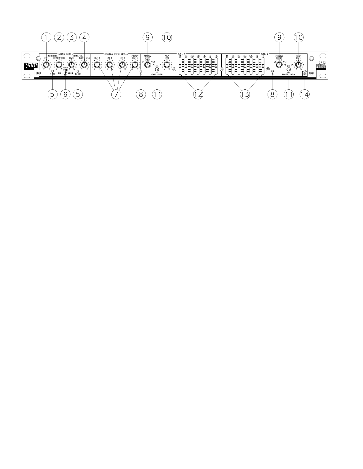
FRONT PANEL DESCRIPTION
1. MICROPHONE LEVEL control: Adjusts the level for the paging microphone. The initial level is set by the MIC TRIM on
the rear panel so that this control can have the greatest range without distortion or feedback.
2. MICROPHONE DUCKER SENSITIVITY control: Sets the sensitivity at which the microphone signal ducks the program
material for paging purposes. If the ambient background noise level is high this control should be set lower to prevent false
triggers. A microphone with a switch is recommended.
3. PHONE/LINE LEVEL control: Sets the level for the phone system paging or voice line input.
4. PHONE/LINE DUCKER SENSITIVITY control: Sets the sensitivity at which the phone/line signal ducks the program
material for paging purposes. If the ambient background noise level is high this control should be set lower to prevent false
triggers.
5. IN USE LEDS: Indicate the source of the page. Also useful in determining why a pager is locked out due to the priority
page lockout feature. (See PAGING PRIORITY INTERNAL JUMPER OPTION described on page Manual-4.)
6. Front panel ZONE ASSIGN switch: Selects which zone the rear panel selected paging input will be routed to and activate
program ducking. (For more information see the REMOTE ZONE ASSIGN INPUT JACK section on page Manual-4.)
7. PROGRAM INPUT LEVEL controls: Adjust the relative levels of each of the four program inputs.
8. OVERLOAD LEDS: Indicate overload for the post-EQ, pre-zone signals.
9. PROGRAM SELECT rotary switch: Selects line inputs 1, 2, 3 or the priority/line 4 Input for each zone.
10. ZONE LEVEL control: Independently controls the volume in zone 1 and zone 2.
11. REMOTE CONTROL switch: Disables the front panel PROGRAM SELECT and ZONE LEVEL controls for each zone.
This alsoenables the SOURCE & LEVEL REMOTE jacks on the rear panel for remote control of these functions using the
optional R2 remote control.
12. ZONE 1 stereo graphic equalizer: Adjusts the frequency contour for the stereo zone 1 outputs (±12 dB). When zone 1 is
used in a dual mono mode, both channels receive the same EQ.
13. ZONE 2 mono graphic equalizer: Adjusts the frequency contour for the mono zone 2 output (±12 dB).
14. POWER indicator: Illuminates a warm yellow glow when the CP 62 is connected to an appropriate power source.
Manual-2
Page 3
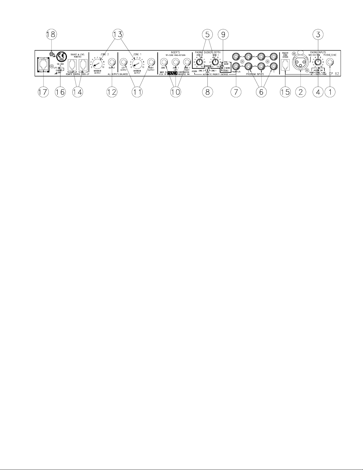
REAR PANEL DESCRIPTION
1. PHONE/LINE PAGING INPUT jack: This ¼" unbalanced TS (Tip-Sleeve) jack connects to a telephone system paging
output or any line level paging signal. Automatic ducking of the program signal occurs during paging.
2. MIC PAGING INPUT jack: This is a 3-pin balanced mic input for paging purposes. Automatic ducking of the program
input signal occurs when a page begins.
3. MIC TRIM control: This adjusts the microphone preamp initial gain, preventing possible feedback or distortion.
4. PAGING INPUTS ASSIGN switch: This switch determines which paging input can be remotely zone assigned. (See the
REMOTE ZONE ASSIGN INPUT JACK section on page Manual-4.)
5. PAGING DUCKER DEPTH control: When paging occurs, these controls set the volume of the program material. They
are adjustable from essentially off at “0” (no program sound) to about 3 dB below the paging level at “10”.
6. PROGRAM INPUT jacks 1-3: These stereo pairs of RCA connectors are line level inputs, suitable for the audio outputs of
VCRs, CD players, tape recorders, tuners, etc.
7. PROGRAM INPUT PRIORITY/4 jack: When a signal appears at this input, the CP 62 automatically switches to this input
no matter which source was selected previously. When the signal ceases, the original input slowly fades back after 35
seconds. (This option is defeatable: see LINE 4 INPUT PRIORITY INTERNAL JUMPER OPTION on page Manual-4.)
8. AUTOMATIC PRIORITY OVERRIDE ASSIGN switch: Selects at which zone the signal at the LINE 4/PRIORITY input
is heard. You may choose ZONE 1, ZONE 2 or BOTH.
9. ZONE 1 MODE switch: Determines if zone 1 remains in stereo or if the program input left and right are summed to mono.
When ZONE 1 MODE is set to MONO, this provides two separate mono zones with the same source and EQ. Separate
levels are accessible by daisy-chaining two optional R2 remote control units for a total of three remote controllable zones
(see page Manual-5 for more information).
10. ZONE 1 & ZONE 2 INSERT jacks: These unbalanced, ¼" Tip=Send, Ring=Return connectors allow insertion of external
signal processors such as equalizers or compressor/limiters. Zone 1 is stereo or dual mono. If zone 1 is used as dual mono,
ZONE 1 LEFT and ZONE 1 RIGHT may use separate processing.
11. Balanced ZONE 1 OUTPUT jacks: These balanced ¼" TRS (Tip-Ring-Sleeve) connectors provide signal to the zone 1
amplifiers. These outputs are wired Tip = “+”, Ring = “–”, and Sleeve = ground, and should be connected to balanced
equipment whenever possible. Unbalanced ¼" TS connectors and wiring work if cable lengths are kept short (under 10 feet
to the amplifiers). Consult the included RaneNote 110 “Sound System Interconnection” for wiring conventions.
12. BALANCED ZONE 2 OUTPUT jack: This balanced ¼" TRS connector provides a mono signal to the zone 2 amplifier.
This output is electronically balanced and wired as above.
13. ZONE 1 & 2 MAXIMUM OUTPUT controls: These screwdriver trim adjustments turn down the maximum output
available to zone 1 or zone 2.
14. SOURCE & LEVEL REMOTE connectors: These modular jacks connect optional Rane R2 remotes to control program
and level in each zone.
15. REMOTE ZONE ASSIGN connector: This modular jack connects with the optional Rane R1 remote control. This
connector allows remotely assigning the zone(s) for either the MIC or PHONE/LINE, depending on the position of the rear
panel PAGING INPUTS ASSIGN switch. (See #4 above.)
16. SIGNAL GROUND LIFT switch: This switch provides the ability to separate chassis and signal ground. Normally, this
switch should be in the “grounded” position. In some circumstances, the opposite position eliminates stubborn hum and
buzz problems. Always turn your amplifier down before switching your grounds.
17. POWER input connector: This product requires a Rane RS 2 power supply. This is not a telephone jack! This calls for an
18-24 VAC center-tapped transformer. Consult the factory for replacement or substitution.
18. Chassis ground point: The CP 62 must be earth grounded. This screw allows attachment of a wire, allowing a secure
electrical connection to the chassis of the CP 62. See the CHASSIS GROUNDING note on page Manual-8 for details.
Manual-3
Page 4

CP 62 CONNECTION
This section covers the most basic of systems. This
product is very versatile, so variations on system hookup are
encouraged to get the most out of your application. The CP
62 chassis must be earth grounded via a wire connected from
the chassis ground screw on the rear of the unit to a known
earth ground. When first connecting the CP 62 to other
components, leave the power supply for last. That goes for
the power in all other components of the system as well. This
allows you to connect the cables and make sure they are
correct without damaging your speakers, ears and nerves.
PROGRAM INPUTS 1-3
The program inputs are conventional unbalanced RCA
phono jacks. Connect these inputs to any line level signal
source such as a CD player, cassette player, AM/FM stereo
tuner, VCR audio outputs, VDP audio outputs, TV audio
outputs or music service.
LINE 4/PRIORITY INPUT
This input uses the same connector as inputs 1-3 above
but with a priority function. When signal appears at this input,
the CP 62 automatically switches internally from whatever
PROGRAM INPUT is selected on the front panel to the LINE
4/PRIORITY INPUT. An AUTOMATIC PRIORITY OVERRIDE switch on the rear panel determines which zone(s) this
input overrides. When the line 4 signal is absent for more than
30 seconds, the CP 62 automatically switches back to the
previous signal source and slowly fades the audio level from
silence to normal volume (nice touch, eh?). It can be used for
Jukeboxes or any intermittent music source that gets turned
on and off. Some examples of intermittent sources would
include compact disc players, cassette decks or karaoke. If a
TV is connected, simply turning on the TV will automatically
switch the CP 62 from music to TV. Turning off the TV
defaults back to the previous program source. This feature
provides an easy switch for transparent operation.
PAGING INPUTS
There are two. The MIC input is a 3-pin balanced connector. The PHONE/LINE input is an unbalanced ¼" TS phone
jack intended to connect to the telephone system’s paging
output transformer or any other line level paging source.
ZONE OUTPUTS
These are ¼" TRS balanced phone jacks. ZONE 1
OUTPUT provides a stereo zone. The ZONE 1 MODE switch
can convert this to dual mono or stereo.
When in MONO, it is possible to use zone 1 as two mono
zones with the same source. The individual dual mono levels
are set by daisy chaining two optional R2 remote controls.
This overrides the front panel level control.
SOURCE & LEVEL REMOTE INPUTS
Two 4-pin modular jacks on the rear control source and
level remotely using an optional R2 remote control unit for
each zone.
REMOTE ZONE ASSIGN INPUT JACK
If only one paging input (MIC or PHONE/LINE) is
required, this jack needs no connection. Just set your chosen
input on the rear PAGING INPUT ASSIGN SWITCH: to the
right for MIC or to the left for PHONE/LINE. This gives zone
assign control to the front panel ZONE ASSIGN switch.
However, if two separate paging inputs are desired, this
jack must be used. There are two connection options:
1. The optional R1 remote control unit: The R1 allows
remote selection of paging ZONE 1, ZONE 2 or BOTH (just
like the front panel ZONE ASSIGN switch – only up to 200
feet away!). The R1 is selected to control either the MIC or
PHONE/LINE input via the rear PAGING INPUT ASSIGN
SWITCH. The front panel ZONE ASSIGN switch defaults to
the other input.
2. The supplied configuration adaptor: With this we hardwire (literally) the setting normally selected by the R1. To
select zone 1, connect the black & green wires together. To
select zone 2, connect the black & red wires together.To
select both zones, connect the black, red & green wires
together. Insulate all wires when through with this procedure.
NOTE: You must use straight copper stranded telephone
wire (not tinsel wire) for the remote hookups—200 feet
maximum of 28-26 gauge 4 conductor telephone wire.
PAGING PRIORITY INTERNAL JUMPER OPTION
If you use only one paging input, the position of this
jumper is unimportant. However, if both paging inputs are
used, this jumper determines priority if paging occurs
simultaneously. The other input is temporarily locked out
under this condition.
This feature is set from the factory in the MIC priority
position. To change priority to the PHONE/LINE input,
disconnect any power to the CP 62, remove the top cover, and
refer to the assembly diagram in this manual. Locate J21,
located in the left center of the board. Lift the jumper from
the MIC side and replace it on the PHONE side. Replace the
cover. Now the PHONE/LINE input overrides the MIC input
in case of a simultaneous page.
LINE 4 INPUT PRIORITY INTERNAL JUMPER OPTION
To defeat the automatic line 4 priority switching, disconnect any power to the CP 62, remove the top cover, and refer
to the assembly diagram in this manual. Locate and remove
the J22 jumper (or offset it one pin). This jumper is located
behind the MIC INPUT jack. Replace the cover. Automatic
override is defeated.
Manual-4
Page 5

CP R1 Zone Assign Remote
Control
When installing the R1 Remote, locate it next to the
paging source. This lets the user select the zones where the
page is to be heard. The R1 connects to the REMOTE ZONE
ASSIGN jack next to the paging inputs on the rear of the
CP 62.
CP R1 with One Paging Source:
Either Mic or Phone/Line
The front panel PAGING ZONE ASSIGN switch (see
Front Panel, balloon #6) lets you assign the paging signal to
ZONE 1, BOTH or ZONE 2. Similarly, the CP R1 remote lets
you assign one of the Paging Sources to either or both Zones.
Which signal is controlled from the front panel PAGING
ZONE ASSIGN switch and which is controlled via the rear
panel REMOTE ZONE ASSIGN connector (Rear Panel,
balloon #15) is determined by the rear panel PAGING
INPUTS ASSIGN switch (see Rear Panel, balloon #4). The
rear panel switch controls the front panel switch and the rear
panel connector.
To use only one paging signal and control it from the
front panel of the CP 62: set the rear panel PAGING INPUTS
ASSIGN switch to PHONE to control the PHONE/LINE
signal from the front panel of the CP 62, or to MIC to control
the MIC signal from the front panel.
Use the CP R1 remote to control one paging source from
another location. In this scenario, set the rear panel PAGING
INPUTS ASSIGN switch to MIC to control the XLR MIC
signal via the remote or set the switch to PHONE/LINE to
control the PHONE/LINE signal from the CP R1 remote.
Two Paging Sources
with No CP R1 Remote Control
When using both paging inputs but not the CP R1 remote
you do need to plug in and set the configuration adapter, (the
short piece of wire with the phone plug and stripped wires
included with the CP 62.) This adapter tells the CP 62 where
one of the paging sources needs to go. The front panel
PAGING ZONE ASSIGN switch (see Front Panel, balloon
#6) routes one paging source and the configuration adapter
routes the other.
SETTING THE CONFIGURATION ADAPTER:
To page only in ZONE 1 twist the black and green wires
together.
To page only in ZONE 2 twist the black and red wires
together.
To page in BOTH Zones twist all three (black, red, and
green) together.
Ignore the cowardly yellow wire, it serves no purpose.
CP R1 with Two Paging Sources:
Both Mic and Phone/Line)
When using both paging sources, the rear panel PAGING
INPUTS ASSIGN switch controls two functions (see Rear
Panel, balloon #4). Which signal is controlled from the front
panel PAGING ZONE ASSIGN switch (see Front Panel,
ballon #6) and which signal is controlled by the REMOTE
ZONE ASSIGN connector (Rear Panel, balloon #15, the place
you plug in the CP R1 remote.)
To use the CP R1 remote to control the XLR MIC signal
set the rear panel PAGING INPUTS ASSIGN switch to the
MIC position. To control the PHONE/LINE signal, set the
PAGING INPUTS ASSIGN switch to the PHONE/LINE
position.
Manual-5
Page 6

CP R2 Source & Level Remote
Control
Table 1 shows the flexibility of configuring the R2. The
R2 controls operate the same as the PROGRAM SELECT and
ZONE LEVEL controls on the front of the CP 62, when
enabled by the front panel REMOTE CONTROL button.
ZONE 1 STEREO MODE
Locate and set the switch in the R2 to STEREO, as shown
in Figure 1a.
ZONE 1 MONO MODE
This delivers a total of three mono zones from the CP 62.
Zone 1a and 1b use the same source with independent
LEVEL controls. To separate Zone 1 into 1a and 1b, use two
R2 remotes connected to Zone 1. Plug a cable from the MAIN
jack of the first R2 into the ZONE 1 REMOTE jack on the
back of the CP 62 and set the first R2s slide switch to DUAL
MONO, as shown in Figure 1b. Plug a cable from the MAIN
jack of the second R2 into the AUX jack on the first R2. A
third R2 plugged into the CP 62 ZONE 2 REMOTE jack
gives control over the third mono zone, operated as Zone 2.
Figure 1a. Figure 1b.
Table 1. R2 Installation Options
Desired Configuration Remote Functions Zone 1 Mode R2 Connections
1 Stereo Zone (Zone 1) SELECT & stereo LEVEL STEREO CP 62 ZONE 1 SOURCE & LEVEL jack
1 Mono Zone (Zone 2) SELECT & mono LEVEL not applicable CP 62 ZONE 2 SOURCE & LEVEL jack
Both of the above both as above STEREO 2 R2 units both as above
3 Mono Zones (Zones 1a, 1b, & 2)
Zone 1a and 1b use the same
Source Selection
Independent mono LEVEL
for Zone 1a, 1b, and 2.
SELECT for Zone 1a & 1b.
SELECT for Zone 2.
MONO Use 3 R2s. Zone 1a - first R2’s MAIN to the CP 62
ZONE 1 SOURCE & LEVEL jack. Zone 1b - second
R2’s MAIN to the first R2’s AUX jack. Zone 2 - third
R2 to CP 62 ZONE 2 SOURCE & LEVEL jack.
Manual-6
DECORA is a registered trademark of Leviton Manufacturing Co., Inc.
Page 7

Preparing the cables
All modular connectors are not created equal. The typical
modular plug that connects to your telephone is a 6-position/
4-conductor connector, named by an RJ number to describe it
(i.e. RJ11, RJ14). This type of connector will not fit into the
CP 62 remote outlets. The appropriate connector for the CP
62 is a 4-position/4-conductor, and is referred to as a “telephone modular handset connector”. It does not have an RJ
number to describe it. Most companies have their own
different part numbers for this part.
1. Install standard copper stranded 28-26 guage 4 conductor
flat telephone cable to an empty electrical box where the
remote is to be located. Do not use high flexibility tinsel
cable. Strip an end to check if necessary. The ampere
rating for tinsel wire is too low, affecting system remote
reliability. Maximum cable distance from the CP 62 is 200
feet.
2. Install a modular handset connector on each end of the
telephone cable, taking note of wire colors as shown in
Figure 4. Special crimp hand tools and the connectors may
be purchased at commercial telephone supply outlets. This
tool is different than standard telephone modular line types.
3. Plug one end into the MAIN jack of the remote control
unit. Connect the other end to the desired jack on the back
of the CP 62.
Figure 2. Installation
Installation
The R1 and R2 remote control units will mount in
standard U.S. electrical boxes in the same way as wall
switches or outlets, as shown in Figure 2. Use a DECORA
wall plate or equivalent to allow the labeling on the front of
the remote to be visible. DECORA wall plates are available in
a wide range of colors at most hardware stores.
®
Figure 4. Remote connector wiring
Manual-7
Page 8

Figure 3b. Stereo and Mono Zone Control Example
Figure 3a. Three Mono Zones Control Example
IMPORTANT NOTE
CHASSIS GROUNDING
The CP 62 is supplied with a rear mounted ground-lift switch. The unit is shipped with this switch in the “grounded”
position, tying circuit ground to chassis ground. If after hooking up your system it exhibits excessive hum or buzzing, there
is an incompatibility in the grounding configuration between units somewhere. Your mission, should you accept it, is to
discover how your particular system wants to be grounded. Here are some things to try:
1. Try combinations of lifting grounds on units that are supplied with ground lift switches or links.
2. Verify that all chassis are tied to a good earth ground, (i.e., through the line cord grounding pin or grounded amplifier
chassis.) Do not depend on the painted rack screws and rails to ground the chassis.
3. The CP 62 does not ground the chassis through the line cord. Make sure that these units are grounded either to another
chassis which is earth grounded, or directly to the grounding screw on an AC outlet cover by means of a wire connected to a
screw on the chassis with a star washer to guarantee proper contact.
Please refer to RaneNote 110, “Sound System Interconnection” included in this manual for further information.
©Rane Corporation 10802 47th Ave. W., Mukilteo WA 98275-5098 TEL (206)355-6000 FAX (206)347-7757 WEB http://www.rane.com
All features & specifications subject to change without notice. SEP96Printed in the U.S.A. on Recycled Paper
Manual-8
 Loading...