

Page 1

OPERATORS MANUAL CP 31
COMMERCIAL PROCESSOR
QUICK START
If you were the type that cheated on school book reports by just skimming through the reading assignments, then this
section is for you! It gives you not quite enough information to really know what you’re doing. But, if you follow the
recommended set up procedure, you should get at least a “B.” This thing is pretty easy to set up…a “C” will pass.
Keep the amplifiers and the CP 31 turned off until all connections are made. The unit does not ground the chassis
through the power cord. It is important that the unit be grounded (required by law in most installations).
PAGE INPUT: Connect the PAGING INPUT to the Euroblock on the rear panel. On the front, select the appropriate MIC
or LINE switch position. Then set the gain with the PAGING TRIM control, then set the PAGING DETECT THRESH-
OLD and finally the PAGING LEVEL. Set the HIGH/LOW CUT FILTER switch located on the rear panel as desired.
PROGRAM INPUTS: Connect line level program sources to the RCA PROGRAM INPUT jacks and engage the MONO
switch if desired. Set the PROGRAM INPUT LEVELS.
EXPAND OUTPUT: Wire the EXPAND Output Euroblock as required to a mono feed delivering PAGE-only or PRO-
GRAM-only signal, depending on the rear panel switch setting. This Output uses a line driver that may be used balanced or
unbalanced. Adjust the EXPAND LEVEL trim as desired.
DUCKER: With the DUCKER switches ON, and a Program source playing, speak into the mic and adjust the DUCKER
DEPTH to control the Program level during a page. Program will return to its previous volume after the page has finished.
ZONE OUTPUT: The ZONE OUTPUT uses a line driver that may be used balanced or unbalanced. Set the LEVEL
control as required.
A highly recommended setup procedure appears on page Manual-4. By following it you will encounter fewer problems
and reduce the need to increase our collective phone bills.
CAUTION: Never connect anything except an approved Rane Power supply to the thing that looks like a red telephone jack on the rear of the CP 31. This is an 18 VAC center tapped power input. Consult the Rane factory for replacement.
CP 31 CONNECTION
Be sure the power is OFF until all connections are made.
EUROBLOCK CONNECTIONS
All Input and Output connections are made with Euroblock connectors except for the RCA Program Inputs. When
wiring to Euroblocks, a minimum wire gauge of 22 AWG is
preferred for reliability. If the ground or shield wire is left
shorter, it acts as a strain relief for the other wires. Cable with
a flexible jacket is easier to use and less likely to damage the
connections. Avoid stripping excess insulation. Inspect wires
for nicks that may lead to wire breakage. Fully insert each
wire in the appropriate socket and tighten the screw.
The Page Input circuit is a true instrumentation amplifier
and operates balanced or unbalanced. Expand and Zone
Outputs are balanced line drivers. Wiring is usually the same
for both Inputs and Outputs. Balanced operation is highly
recommended. Balanced wiring is straight forward, (+) to (+),
WEAR PARTS: This product contains no wear parts.
(–) to (–) and shield to shield.
For unbalanced operation, use single conductor cable with
shield. Connect (+) to (+) and the shield/ground wires to the
shields at both ends. Do not connect the (–) pin. When
unbalanced wiring is used, it is very important for the CP 31
and any other unit in the system to have good earth or
technical grounds. If a unit is located far from the CP 31
(greater than ten feet) or is of a type that might create grounding problems, use isolation transformers.
Refer to the included RaneNote 110, “Sound System
Interconnection” for more information on proper wiring
procedures.
PROGRAM INPUTS
The stereo or dual-mono Program Inputs connect to RCA
jacks. These Inputs are unbalanced. The same guidelines
given above for unbalanced operation apply to these Inputs.
Manual-1
Page 2
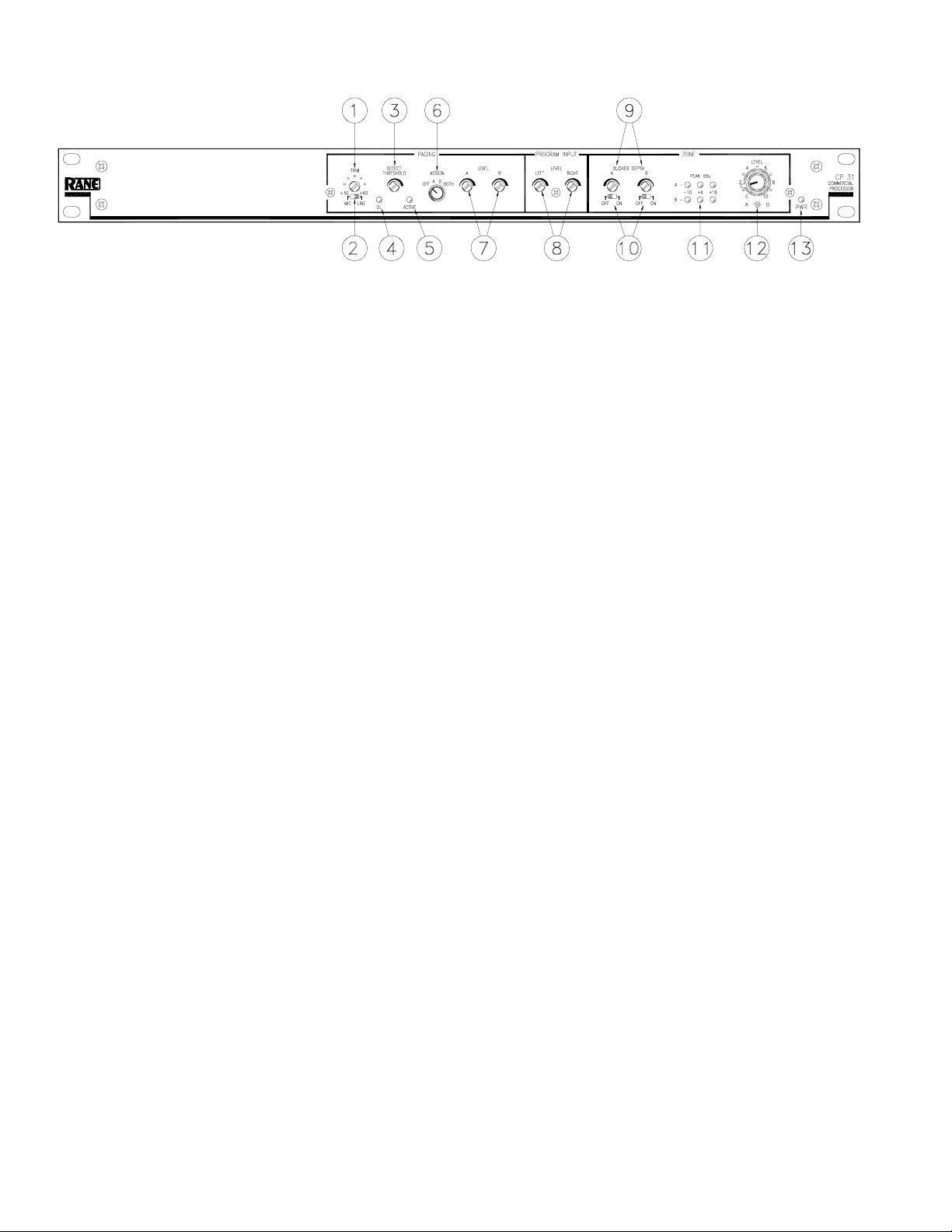
CP 31 - FRONT PANEL
PAGING TRIM control is used to adjust the Page Input preamplifier gain to match the microphone/source in use, not to set
the Page level at the Zone Output. The range is 30 dB to 60 dB.
PAGING MIC/LINE switch selects a 30 dB Input pad when set to LINE.
PAGING DETECT THRESHOLD sets the Page signal level required to gate a Page on and illuminate the ACTIVE
indicator (#5). The range is -∞ (on) to +4 dBu.
PAGING OL (Overload) indicator lights when the Page Input preamplifier comes within 4 dB of clipping.
ACTIVE indicator lights when the Page signal level reaches the Paging Detect Threshold. Note that a Page is always Active
when the PAGING DETECT THRESHOLD is set to minimum (ccw).
PAGING ASSIGN switch selects whether the Page signal is sent to Zone A, Zone B, BOTH Zones, or OFF (no Zones).
PAGING LEVEL controls adjust the Paging Level in each of the two (A & B) Zones.
PROGRAM INPUT LEVEL controls allow independent level adjustment for the stereo or dual mono Program Input(s).
ZONE DUCKER DEPTH control sets the Ducker Depth (the amount of Program attenuation during a Page) from 50 dB
(ccw) to 6 dB (cw). The Ducker release is ramped and not user-adjustable.
ZONE DUCKER OFF/ON switches independently turn each Ducker ON or OFF.
ZONE Output Meter displays PEAK signal levels at -10 dBu, +4 dBu, and +16 dBu.
ZONE LEVEL controls adjust the overall Level for each Zone Output. This concentric pot allows independent adjustment
of Output Levels, or “stereo/master” level control by holding both the inner and outer knobs together.
PWR indicator lights when the CP 31 is connected to a powered RS 1 power supply.
Manual-2
Page 3

CP 31 - REAR PANEL
Chassis Ground Screw provides a convenient earth (technical) ground connection point. The CP 31 does not ground the
chassis through the power cord. It is important that the unit be grounded (required by law in most installations).
POWER jack accepts the mod plug from a Rane RS 1 remote power supply (included) or an optional Rane RAP 10 power
supply. This is not a telephone jack. Use of a supply not approved by Rane may damage the unit and void the warranty.
ZONE OUTPUT Port features a balanced line driver with a Euroblock connector. These Left and Right Outputs may be
wired balanced or unbalanced.
EXPAND OUTPUT Port features a balanced line driver with a Euroblock connector. This mono Output may be wired
balanced or unbalanced.
EXPAND OUTPUT switch assigns PAGE-only or PROGRAM-only as the source for the Expand Output.
EXPAND OUTPUT LEVEL trim adjusts the signal level delivered to the EXPAND OUTPUT.
PROGRAM INPUT MONO switch, when pressed in, sums the left and right Program signals to provide a mono signal
available at both A and B Zone Outputs. Mono program summing is before page summing, so A & B Paging Levels remain
independent when MONO is engaged.
PROGRAM INPUTS may be used as a stereo pair, or dual mono unbalanced sources.
PAGING INPUT HIGH/LOW CUT FILTER switch, when IN, limits the bandwidth of the Paging Input from 100 Hz to 7
kHz, improving intelligibility in some installations. The Paging detector is always bandlimited to 100 Hz to 7 kHz.
PAGING INPUT Euroblock connector may be wired balanced or unbalanced.
INTERNAL PAGING PRE/POST ZONE LEVEL
SWITCHES
As shipped from the factory, the Zone LEVEL controls on
the front of the CP 31 only control Program level, so Page
volume will always be heard as set by the PAGING LEVEL
controls. The internal Paging Pre/Post Zone Level switches
are shipped from the factory in the POST position. If desired,
the switches may be set to PRE, allowing the Zone LEVEL to
control both Program and Page, mixing mic and line.
To change these switches, be sure power is disconnected.
Remove the top cover of the unit and locate the switches on
the circuit board as shown to the right. Replace the top cover.
PAG E SUM SWITCHES
Manual-3
Page 4

RECOMMENDED CALIBRATION PROCEDURE
The CP 31 is a versatile instrument. While this allows it to conform to the requirements of a number of system applications,
it also results in complexity. For this reason, it is very important to use an organized approach to system calibration. Once the
system is connected and the internal switches set for your specific application, take the time for proper calibration. The
following is an ordered list of system adjustments that makes calibration easy, and results in optimum performance.
This procedure assumes that a microphone is used for the Page. The procedure (except for the exact wording) is the same
for other Page sources (e.g., telephone, etc.).
See the Internal Pre/Post Zone Switches note on page Manual-3 before installing the unit.
Make sure the POWER is off!
PREFLIGHT CONTROL SETTINGS
PAGE SETTINGS:
• MIC/LINE Pad As required (front panel)
• Gain TRIM 12:00 (center) (front panel)
• DETECT THRESHOLD Min (ccw, Active) (front panel)
• Paging LEVEL A & B Min (front panel)
• PAGING ASSIGN BOTH (front panel)
• HIGH/LOW CUT FILTER As required (rear panel)
PROGRAM INPUT SETTINGS:
• Input Levels Min (front panel)
ZONE SETTINGS:
• DUCKER DEPTH 2:00 (about 15 dB) (front panel)
• DUCKER OFF/ON OFF (front panel)
• Zone LEVEL A & B Max (front panel)
• Zone Output MONO As required (rear panel)
• Zone Expand PROGRAM/PAGE As required (rear panel)
• Expand Output LEVEL As required (rear panel)
SYSTEM CONNECTIONS
• Connect page microphone or line-level paging source
• Connect Program source(s)
• Connect Output(s) to amplifier(s) or destination(s)
CALIBRATION
1. Connect the RS 1 power supply and verify the Power indicator lights.
2. Verify the Zone LEVEL controls are set to maximum and that an active source is playing to the Program Inputs. Adjust the
PROGRAM INPUT LEVELS to be the very loudest you would ever desire.
3. Adjust the Zone LEVEL control to a comfortable listening level.
4. Note that with the Paging LEVEL set to minimum, the following Page will not be heard. Speak very loudly (bark) into the
Paging mic. Adjust the Paging TRIM control so that the Paging Overload indicator just lights. It is important to set the gain
of the pre-amp before setting the Paging Detect Threshold.
5. Speak into the Paging mic in a normal voice and adjust the Paging DETECT THRESHOLD so the ACTIVE indicator lights
only during speech. If the Paging DETECT THRESHOLD is set too low, the Pager may gate on due to background sound.
6. With a Program source playing, speak into the Paging mic. Adjust the Paging LEVEL control to provide the correct Page-to-
Program mix. If the Paging DETECT THRESHOLD is set too high, there may be a delay before speech is heard. To correct
this, lower the Paging DETECT THRESHOLD setting.
7. Set the DUCKER switches to ON. With a Program source playing, speak into the Page mic and adjust the DUCKER DEPTH
to the desired level of Program during a Page.
You’re all set. Enjoy.
©Rane Corporation 10802 47th Ave. W., Mukilteo WA 98275-5098 TEL (425)355-6000 FAX (425)347-7757 WEB http://www.rane.com
Manual-4
103138
 Loading...