

Page 1
OPERATORS MANUAL AVA 22d
AUDIO VIDEO ALIGNMENT DELAY
QUICK START
Look around to make sure no one catches you reading this. You’re aware this is the manual aren’t you? Wow! Most
people only get about this far in a manual, but there are a few important things you should know about the AVA 22d. So
please keep reading. These few points are summarized in this Cliff Note version of the manual.
The first time you power the AVA 22d it is in BYPASS, and functions like an expensive wire. This is useful for initial
troubleshooting and allows for convenient verification of signal flow. Punching the BYPASS buttons and extinguishing
their LEDs will activate the Delays.
ADJUSTING SENSITIVITY—First apply a signal with nominal input level and adjust the SENSITIVITY controls so
the red CLIP LEDs just light, then back off so the LEDs do not turn on, even with high signal peaks.
SETTING DELAY—Now that the input signal is calibrated, select LINK mode (LINK LED on) for stereo operation,
or turn off LINK mode for dual mono operation. Adjust the up/down buttons until the LED display shows the desired
Delay.
STORING DELAY—Press the STORE button (the STORE LED turns off). This stores the current Delay values into
each Channel’s current Memory (A or B). The current Memory is indicated by the lit MEMORY LED for each Channel.
Both Channel’s current Delay values are stored with each press of the STORE button. The broadcast Mode (NTSC or PAL/
SECAM) is also stored with the Delay value.
RECALLING DELAY—To recall a stored Memory, press RECALL. Each press of this button alternately recalls
stored Memories (A then B then A…).
Never connect anything except an approved Rane power supply to the thing that looks like a telephone jack on the
rear of the AVA 22d. This is an AC input and requires special attention if you do not have a power supply exactly like the
one originally packed with your unit. See the full explanation of the power supply requirements elsewhere in this manual.
600 ohm users see page Manual-4.
WEAR PARTS: This product contains no wear parts.
Manual-1
Page 2
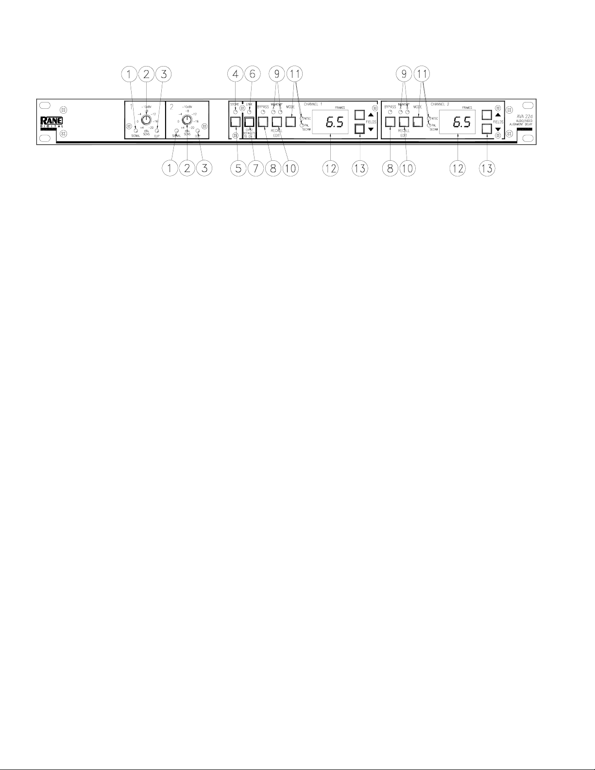
FRONT PANEL DESCRIPTION
SIGNAL indicators: These green LEDs illuminate approximately 42 dB before actual clipping.
SENSITIVITY controls: These rotary controls vary incoming signal levels to the A to D converter. The output signal is
also adjusted so the AVA 22d always passes signal with unity gain into 600 ohm loads. (See operating instructions.)
CLIP indicators: These red LED indicators illuminate 4 dB before clipping at the A to D converter input.
STORE indicator: This flashing LED indicator alerts the user that the current configuration of the AVA 22d is different
from the stored configuration. The STORE LED is off when the current configuration matches the stored configuration.
STORE button: This pushbutton stores both Channels’ current Delay configurations into the given Channels’ current
Memory (A or B). The current Memory for each Channel is indicated by the lit MEMORY LED for that Channel.
LINK indicator: This green LED lights when the unit is in LINK mode. LINK mode allows stereo operation.
LINK button: This pushbutton toggles between LINK mode (stereo operation) and DUAL MONO operation. (See Operat-
ing Instructions.)
BYPASS buttons and indicator: These momentary push buttons toggle each Channel’s hard-wired Bypass. If an LED is
on, the given Channel is Bypassed and functions like a wire. If it is off the given Channel is active.
MEMORY indicator: These LEDs indicate the most recently recalled Memory, A or B, for the given Channel. They also
indicate the Memory that is written to when the STORE button is pressed. The MEMORY LED flashes when the current
Delay value for that Channel is different than the stored value for that Channel.
RECALL buttons: Pressing one of these pushbuttons alternately Recalls stored Memories A and B for the given Channel.
MODE buttons and indicator: These buttons toggle the broadcast mode for the given Channel, NTSC or PAL/SECAM.
Each Channel contains LEDs indicating the current broadcast Mode.
FRAMES displays: These 2-digit displays indicate the current Delay value for the given Channel. On power up this display
also shows the currently installed software revision level.
UP/DOWN buttons: Pressing these buttons increases/decreases the amount of Delay in the given Channel.
Manual-2
Page 3

REAR PANEL DESCRIPTION
XLR INPUT/OUTPUTS: Nothing new here, balanced Ins and Outs. If you can tolerate unbalanced characteristics (like
hum), you can also wire the AVA 22d in an unbalanced configuration. See RaneNote 110, “Sound System Interconnection”
located elsewhere in this manual.
Front panel lockout switch: Enables the Front Panel Lockout mode. In this mode all front panel controls, with the excep-
tion of the RECALL buttons, are disabled. Press a RECALL button while in LOCKOUT to temporarily display, but not
Recall, the value of the other stored Memory for the given Channel. (See Operating Instructions for optional Bypass
Lockout mode.)
REMOTE RECALL & BYPASS terminals: Wiring external configuration switches to these terminals allows remote
stereo bypassing or stereo memory recalling of the two nonvolatile memories. These terminals use CMOS (+5 volt) logic
levels and source only 0.5 mA (max) each.
POWER connector: No, this is not where commissioner Gordon plugs in his Bat-phone, in fact it is not a telephone jack at
all. The AVA 22d uses an 18 volt AC center-tapped transformer only. Use only a model RS 1, RAP 10 or other remote AC
power supply approved by Rane. The AVA 22d is supplied with a remote power supply suitable for connection to this jack.
Consult the factory for replacement or substitution.
Chassis ground point: A #6-32 screw and toothed washer is provided for chassis ground. Since the AVA 22d does not get
chassis ground through the AC cord, this point is provided if your system does not have another earth ground such as the
rack rails.
FCC NOTICE
This equipment has been tested and found to comply
with the limits for a Class B digital device, pursuant to Part
15 of the FCC Rules. These limits are designed to provide
reasonable protection against harmful interference when the
equipment is operated in a residential installation. This
equipment generates, uses, and can radiate radio frequency
energy and, if not installed and used in accordance with the
instructions, may cause harmful interference to radio
communications. However, there is no guarantee that
interference will not occur in a particular installation. If this
equipment does cause harmful interference to radio or
television reception, which can be determined by turning
the equipment off and on, the user is encouraged to try to
correct the interference by one or more of the following:
1. Re-orient or relocate the receiving antenna.
2. Increase the separation between the equipment and the
receiver.
3. Connect the equipment into an outlet on a circuit differ-
ent from that to which the receiver is connected.
4. Consult the dealer or an experienced radio/TV technician.
CANADIAN EMC NOTICE
This Class B digital apparatus meets all requirements of
the Canadian Interference-Causing Equipment Regulations.
Cet Appariel numerique de la classe B respecte toutes
les exigences du Reglement sur le material broilleur du
Canada.
CHASSIS GROUNDING
If after hooking up your system it exhibits excessive
hum or buzzing, there is an incompatibility in the grounding
configuration between units. Here are some things to try:
1. Try combinations of lifting grounds on units supplied
with ground lift switches (or links).
2. Verify all chassis are tied to a good earth ground.
3. Some units with outboard power supplies do not ground
the chassis through the line cord. Make sure these units
are solidly grounded by tying the Chassis Ground Point
to known earth ground. Use a star washer to guarantee
proper contact.
Manual-3
Page 4

AVA 22d CONNECTION
When connecting the AVA 22d to other components in
your system for the first time, leave the power supply for last.
This gives you a chance to make mistakes and correct them
before any damage is done to your fragile speakers, headphones, ears, or brains. The AVA 22d passes audio while it is
unpowered by virtue of its fail safe bypass relays (when the
AVA 22d functions as a wire). Turn the system volume down
before plugging in the AVA 22d’s power.
INPUTS
The AVA 22d’s Inputs are electronically balanced. Use
only balanced wiring. Pin 2 is “hot” per AES standards.
OUTPUTS
The AVA 22d’s Outputs are balanced line drivers. Pin 2 is
“hot” per AES standards.
REMOTE RECALL TERMINALS
Each Channel of the AVA 22d has two nonvolatile
Memories, “A” and “B”. Connecting a switch between the
GND and MEM terminals permits remote stereo recalling of
the Memories. Only a change in the switch position is sensed.
When the switch closes, both Channels’ Memory B’s are
recalled. When the switch opens, both Memory A’s are
recalled. See Operating Instructions for more details or an
option.
W
600 OHM USER INFORMATION
The AVA 22d’s Inputs are specified for a nominal +4 dBu input, which is a voltage referenced level of 1.228 Volts RMS.
(0 dBu = 0.7746 Volts). At this voltage level, the AVA 22d provides 16 dB of headroom. Users who wish to operate the AVA
22d in 600 ohm systems must provide their own 600 ohm input resistor across the input terminals. This enables the AVA 22d
to accept a +4 dBm input and allows delivery of +4 dBm to a 600 ohm load. Confusion among 600 ohm users of the AVA 22d
may occur if one assumes the input and output impedances of the AVA 22d are 600 ohms – they are not. Therefore, when
evaluating the AVA 22D do not assume that +4 dBm equals +4 dBu unless you have ensured that all input and output impedances in your test setup are 600 ohms.
Advantages of Hi-Z in/Lo-Z out systems:
(from Audio System Design and Installation, by Phillip Giddings, Howard W. Sams, 1990, pp. 129-130.)
1. Less distortion in output due to smaller output current needs.
2. Lower noise pickup by interconnecting lines due to lower source impedance.
3. Greater lengths of cable may be driven for a given high frequency roll-off.
4. Many pieces of equipment can be driven from one output without the use of distribution amplifiers and with no concern for
matching or level changes.
5. Better reliability resulting from less heat generation due to less power drawn from the output stage.
6. Because of the AVA 22d’s 200 ohm output impedance, the addition of a 600 ohm load termination drops the delivered
voltage by about 2.5 dB.
7. Greater signal voltage swing as 6 dB of signal is not lost in the (600 ohm) source impedance.
8. Smaller currents reduce inductive coupling and crosstalk between cables.
Manual-4
Page 5

Frame-to-Millisecond Table
AVA 2 2
Displayed
Frame Value
0.0
0.5
1.0
1.5
2.0
2.5
3.0.
3.5
4.0
4.5
5.0
5.5
6.0
6.5
7. 0
7. 5
8.0
8.5
9
9.5
NTSC Delay
Time in
Milliseconds
0.00 0.00
16.68 20.00
33.37 40.00
50.05 60.00
66.73 80.00
83.42 100.00
100.10 120.00
116.78 140.00
133.47 160.00
150.15 180.00
166.83 200.00
183.52 220.00
200.20 240.00
216.88 260.00
233.57 280.00
250.25 300.00
266.93 320.00
283.62 340.00
300.3 360.00
316.98 380.00
PAL /SECAM
Delay Time in
Milliseconds
Field/Frame Conversion Table
FORMAT Number of Fields
per second
NTSC 59.94 16.68 msec 30 33.33 msec
PAL/SECAM 50 20 msec 25 40 msec
Note: There are 2 fields in a frame.
The AVA 22d’s maximum delay time is 380.00 msec.
This provides up to 9.5 NTSC or PAL/SECAM Frames.
1 Field Equals Number of Frames
per second
1 Frame Equals
Manual-5
Page 6

OPERATING INSTRUCTIONS
Once you've properly connected the AVA 22d to the
system, turn on the power. When the AVA 22d is first
powered, the revision level of the software is displayed.
THE BASICS
The AVA 22d is a two Channel device. Each Channel has
a current Delay value that is always active/heard. You can
only edit the current Delay values. Additionally each Channel
has two nonvolatile Memories, A and B. The current Delay
values can be stored in one of these two Memories.
SENSITIVITY SETUP
The first step is to apply signal and adjust the Sensitivity
controls. If you know the nominal level, adjust the control
indicator to that level. Otherwise, set the Sensitivity control
so high signal peaks just illuminate the CLIP LED, then back
off a little.
ADJUSTING CURRENT DELAY VALUE
One Channel at a time: With the LINK LED off, press
the up/down buttons for the Channel you want to adjust until
the desired Delay value is reached. That’s it!
Both Channels simultaneously: With the LINK LED on,
changing either Delay value changes the other Channel’s
Delay value by the same relative amount. (The Delay values
are linked.) BYPASS, RECALL and broadcast MODE are
also linked together in LINK mode.
When entering LINK mode, Channel 2’s current Bypass
and Memory settings are stored and replaced with Channel
1’s current Bypass and Memory settings. This may cause a
Memory Recall to occur in Channel 2. This Recall may also
include a change in broadcast Mode if the Recalled Memory’s
Mode is different. Channel 2’s stored Delay value is not
changed to match Channel 1’s Delay value. (Channel 2’s
stored delays remain unchanged.) When leaving LINK mode,
Channel 2’s Bypass and Memory settings are restored to their
dual mono settings. Again a Memory Recall may occur, thus
restoring the stored Channel 2 value.
RECALLING DELAYS
Press the RECALL button. Each press of this button
alternately Recalls stored Memories (A then B then A…) for
the given Channel. Pressing RECALL while editing Delay
values writes over the changes you’ve made if you have not
stored them.
REMOTE RECALLS
The rear REMOTE RECALL terminals are functionally
equivalent to the front panel RECALL and BYPASS buttons
while in LINK mode. When the switch closes, both Channels
are Bypassed, or, for the other switch, both Memory B’s are
recalled. Both Channels are activated (or both Memory A’s
are recalled) by opening the switch. These terminals can not
be locked out.
An internal jumper is provided to redefine the REMOTE
RECALL function. (See W3 in the board layout diagram.)
Moving this jumper from its default position redefines the
Stereo Bypass Remote terminal as a Channel 2 Memory
Recall terminal. The other terminal (defaulted as Stereo
Memory Recall) becomes a Channel 1 Memory Recall
terminal. This is convenient for mono video houses, allowing
one equipment room to use Channel 1 and another room to
use Channel 2 independently.
INTERNAL BYPASS JUMPER SETTING
Internal jumpers enable or disable the BYPASS buttons
while in Front Panel Lockout mode. The default setting of
these jumpers disables the BYPASS buttons in Front Panel
Lockout mode. (See W1 and W2 in the board layout diagram.)
HOLE PLUGS
Once your system is properly configured, the Sensitivity
knobs can be removed and the unit secured by replacing the
knobs with the provided hole plugs.
STORING DELAYS
Press the STORE button. The STORE LED turns off. This
Stores the current Delay values into each Channel’s current
Memory (A or B). The current Memory for each Channel is
indicated by the lit MEMORY LED for that Channel. Both
Channels’ current Delay values and broadcast Modes are
stored with each press of the STORE button.
©Rane Corporation 10802 47th Ave. W., Mukilteo WA 98275-5098 TEL (425)355-6000 FAX (425)347-7757 WEB http://www.rane.com
Manual-6
103585
 Loading...