

Page 1
OPERATORS MANUAL AD 22S
AUDIO DELAY
DISTANCE
ALIGNMENT
VIDEO
CHANNEL
CURSOR
CHANNEL 1
RANE AD 22S AUDIO DELAY
LINK
CHANNEL 2
QUICK START
Your AD 22S is out of its box, and now it’s time to integrate it
with your audio setup. But wait! What are these buttons for?
What do all those numbers on the display mean? is guide intends to help you quickly learn the basics and familiarize you with
the device so there’s no delay before you delay.
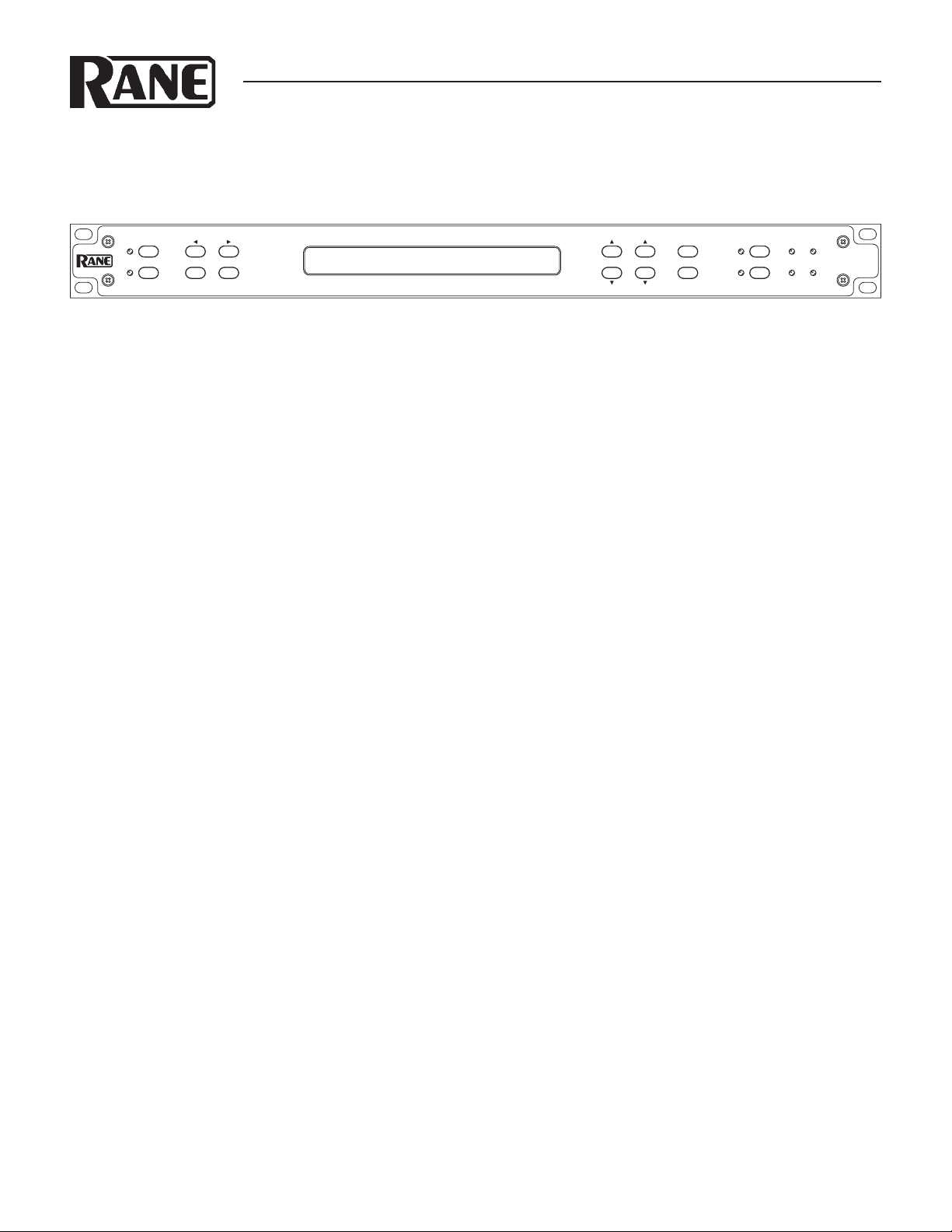
FRONT PANEL CONTROLS
e rst thing to decide is which alignment mode to use. If you’re
using the AD 22S to synchronize audio with video, then select
Video mode. Otherwise select Distance alignment. e DISTANCE and VIDEO buttons on the left hand side of the unit
switch between the two modes. Display settings and delay values
are controlled by using the CHANNEL button to toggle between
channels 1 or 2, and by using the CURSOR buttons to select
the value you wish to change. e COARSE and FINE buttons
increment or decrement the value currently selected.
DISTANCE ALIGNMENT
One of the main applications for the AD 22S is synchronizing
an audio signal coming from separate sources at two dierent
distances. Say, for example, you want the music emanating from
a stack of loudspeakers on the lawn at an amphitheater to get to
your audience at exactly the same time as sound coming from
the speaker arrays on stage. e amount of delay needed is the
time it takes sound to travel from the stage to the lawn. While in
DISTANCE mode, this can be displayed in feet, meters, or milliseconds.
VIDEO ALIGNMENT
e AD 22S is also excellent for synchronizing audio with video
feeds, especially in a live environment where video processing
typically adds several milliseconds to the signal that can have a
noticeable eect on the nal output. To assist in this application, the AD 22S can show your delay value directly in terms of
frames. All common frame rates for NTSC and PAL/SECAM are
supported, and the audio stream can be delayed with a precision
of 0.5 frames to line up perfectly with any video stream.
STORE
MEMORY
FINECOARSE
RECALL
1
BYPASS
2
121
AD 22S
OLSIG
AUDIO DELAY
2
SETTING DELAY
Use the CURSOR buttons to select the unit type, then
press the COARSE or FINE buttons to cycle through options. In
Distance mode, choose between feet, meters, or milliseconds; in
Video mode the delay is shown in frames or milliseconds. If you
know the distance between the sources you are summing, set the
units for feet or meters.
e ambient temperature also aects the speed of sound. To
set the temperature, use the CURSOR buttons to select either °C
or °F, then set the value to the approximate temperature at your
speaker location. e AD 22S calculates the correct delay based
on your environment.
Note: Changing units from distance to time does not change
the output delay. For example, if you are viewing the settings for
channel 1 in meters, a change from meters to milliseconds keeps
the same amount of delay but shows it in milliseconds rather than
distance.
LINKING CHANNELS
e LINK button connects the controls so that all changes apply
to both channels. Channels do not need to share the same setting.
While linked, incrementing or decrementing a value changes the
delay for both channels at once. To treat the channels as a stereo
pair, rst set the delay value to the same setting on both channels
before pressing the LINK button.
MEMORY FUNCTIONS
Each channel has two memory banks, A and B. e * character
at the right of the display indicates that the current setting does
not match what is stored in memory.
Pressing STORE copies the current settings into the selected
Memory, clearing the * character. e cursor must be over the
Memory Bank eld before pressing STORE. To activate a stored
setting, press RECALL to change the active delay to the value
stored in the memory location shown. If channels are linked, both
will be recalled.
Additional features are described in Operation
Details on page Manual-4.
WEAR PARTS: is product contains no wear parts.
Manual-1
Page 2
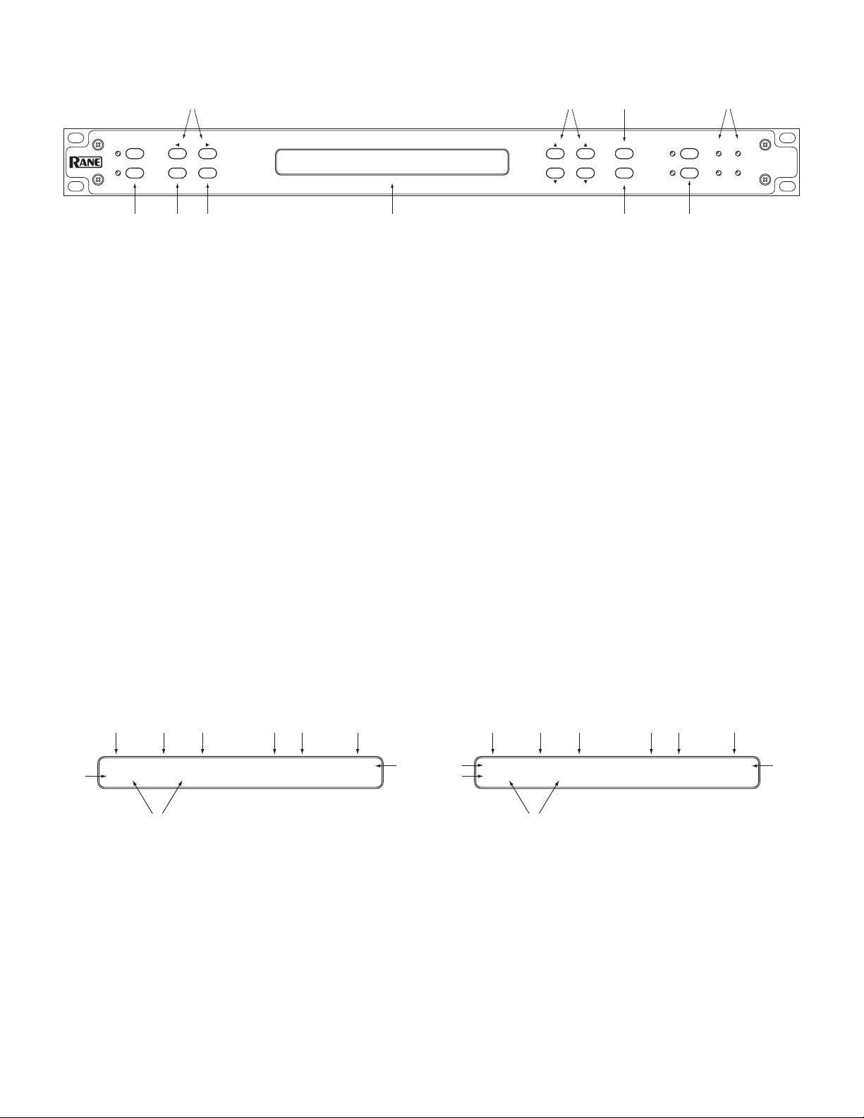
FRONT PANEL DESCRIPTION
4
DISTANCE
ALIGNMENT
VIDEO
CURSOR
CHANNEL
1 2 3
CHANNEL 1
RANE AD 22S AUDIO DELAY
LINK
CHANNEL 2
6 8 9
5 7 0
STORE
MEMORY
FINECOARSE
RECALL
1
2
BYPASS
2
121
AD 22S
OLSIG
AUDIO DELAY
1 ALIGNMENT MODE buttons: Press DISTANCE for delay in feet, meters, or milliseconds. Press VIDEO for alignment by frames
or milliseconds.
2 CHANNEL button: Press this to switch the cursor location between channels. is button has no eect if the channels are linked.
3 LINK button: Links channels together so changes made aect both channels at once. To treat the channels as a stereo pair, make
sure settings for each channel are identical before pressing the LINK button. Press the LINK button again to unlink.
4 CURSOR buttons: Press left or right cursor to select the value for editing.
5 COARSE and FINE controls: ese buttons aect the setting that is currently highlighted to change settings or delay values.
COARSE increments or decrements delay by 1 ms/feet/meters or 1.0 frames, FINE by 0.1 ms/feet/meters or 0.5 frames.
6 LCD Display: Shows the current readout of settings for each channel. Fields may be selected using the CURSOR buttons and
changed using the COARSE / FINE controls. See the DISPLAY sections below.
7 STORE button: Stores the Delay conguration into current memory for the selected channel. If the asterisk * character is shown
to the right of the display, the current value does not match the memory location.
8 RECALL button: Copies the stored delay setting into the active channel. If channels are linked, then both are recalled.
9 BYPASS buttons: Toggle relays for each channel. If LED is on, bypass is enabled and the device functions like a wire. If bypass LED
is o, the channel is active.
0 SIGNAL / OVERLOAD LEDs: SIG LEDs indicate signal presence on the input. OL LEDs light red when an input signal is near
the maximum level and may clip.
3 415 6 7 8
1: 25.50 Feet 80 °F Mem A *
>2:[ 2.74]Meters 27 °C Mem B
2
Distance Mode
DISPLAY: DISTANCE MODE
1 Cursor
2 Active Channel(s)
3 Channel #
4 Delay Setting
5 Units (Feet, Meters, ms)
6 Temperature
7 Temp. Units
8 Mem. Bank
9 Memory Indicator - * Shown if dierent than stored value
9
3 415 6 7 8
>1:[ 2.5]Frames 29.97 fps Mem A *
2
>2:[ 3.0]Frames 29.97 fps Mem A
Video Mode
DISPLAY: VIDEO MODE
1 Cursor
2 Active Channel(s)
3 Channel #
4 Value
5 Units (Frames, ms)
6 Frame rate
7 Units (Frames per second)
8 Mem. Bank
9 Memory Indicator - * Shown if dierent than stored value
9
Manual-2
Page 3

REAR PANEL DESCRIPTION
1
CH 1 INPUTCH 2 INPUT CH 1 OUTPUTCH 2 OUTPUTCH 1 REMOTECH 2 REMOTEFRONT PANEL
100-240 V
50/60 Hz 7 WATTS
COMMERCIAL AUDIO
EQUIPMENT 24TJ
R
AD 22S
MADE IN U.S.A.
RANE CORP.
ACN 001 345 482
This device complies with
Part 15 of the FCC Rules.
Operation is subject to the
following two conditions:
(1) this device may not
cause harmful interference,
and (2) this device must
accept any interference
received, including
interference that may
cause undesired operation.
CONTROL LOCKS
B
D
Y
E
P
L
USB
A
A
S
Y
S
R
B
E
Y
C
P
A
A
L
S
L
S
R
B
CH REMOTE WIRING
E
Y
C
P
A
A
L
S
L
S
OPEN RECALLS “A”
CLOSED RECALLS “B”
CLOSED = BYPASS CH
PIN 2: POSITIVE
PIN 3: NEGATIVE
PIN 1: CHASSIS GND
23456
1 CHANNEL INPUTS: Balanced XLR input jacks, 24 dBu max level.
2 CHANNEL OUTPUTS: Balanced XLR outputs, 600 Ω min. load.
3 REMOTE RECALL terminals: Wire external switches to remotely recall Memory settings or toggle bypass relays. See the
REMOTE RECALL section.
4 FRONT PANEL CONTROL LOCKS: A wired external switch disables the front panel controls to prevent accidental changes.
5 USB FIRMWARE UPDATE: is USB connection facilitates possible rmware upgrades in the future. is port provides no other
functions and should not be connected during normal use. See the FIRMWARE UPDATE section.
6 UNIVERSAL POWER SUPPLY: Universal IEC power jack connects anywhere in the world to AC line voltage, 100-240 VAC @
50 – 60 Hz.
Manual-3
Page 4

OPERATING DETAILS
INITIAL SETUP
e AD 22S is always on while plugged in. When rst powered
up, the LCD briey displays the words “Rane AD 22S Audio
Delay” and the current rmware revision. Out of the box, both
channels are in BYPASS mode with the inputs routed directly to
the outputs. is makes it easy to set up and verify that signals are
present before turning on any delay. e yellow bypass indicators mean that BYPASS is active; press each BYPASS button to
disable.
ALIGNMENT MODE
Two modes of operation are available. If working with video and
wish to set delay by number of frames, press VIDEO for video
alignment. Otherwise press DISTANCE for distance alignment.
Both modes oer milliseconds as a simple display option in addition to their distance or video functions.
SETTING THE DELAY
A ‘>’ by the channel number indicates the channel is selected for
editing. is appears on both channels if LINK is active.
Distance Mode: Use CURSOR buttons to highlight the unit
type, then select between milliseconds, feet, or meters. e
AD22S also needs to know the temperature. To set, select and set
the unit type to °C or °F, then select and set the temperature.
Video Mode: Choose between frames or milliseconds as the display setting. For frames, the delay value is based on the number of
frames per second, denoted by “fps” on the display. Set this rst
and make sure it matches your video frame rate.
Linked Channels: With channels linked, any changes made are
applied to both channels at once. is does not force the delay
values to be the same.
Example: For two speaker arrays at dierent distances from a
performer, linking the two channels lets you change temperature
settings for both at once.
For stereo operation, set each channel to the same value before
pressing LINK.
RECALLING DELAYS
Press RECALL to copy from the Memory shown to the active setting for the selected channel. If LINK is active, both channels will
be recalled. is will overwrite any current settings.
REMOTE RECALL
e REMOTE RECALL terminals on the rear of the unit are
functionally equivalent to the RECALL button. With a switch
wired between the RECALL terminal and the GND terminal,
close the switch to recall Memory B. Open the switch to recall
Memory A.
FIRMWARE UPDATE
Should a rmware upgrade become available, it will be posted
on the AD 22S page at www.rane.com/ad22s.html. e USB port
provides the connection to a PC enabling the le transfer. Perform the following steps to update:
1. Ensure the unit is powered.
2. Connect via device cable to USB port on computer.
3. AD 22S appears as an EXTERNAL DISK device containing
one le (named “AD22S_XX.BIN” or similar).
4. Delete this le. NOTE: After deleting this le, the folder may
disappear, then re-open after a few seconds.
5. Copy or drag the new rmware le to the AD 22S.
6. After transfer, the AD 22S restarts automatically and briey
displays the new revision info. It may also reappear as an EXTERNAL DISK on the PC containing the new rmware le.
7. Disconnect USB cable and resume normal operation.
Notes: If the revision number displayed does not match the new
rmware, make sure you have the latest le and try again.
Tip: Press and hold both CURSOR buttons simultaneously
for one second to view the currently running rmware version.
If an error occurs during transfer or a le is corrupted, the
AD22S will revert to the last working version.
STORING DELAYS
e * character on the display means the current setting differs from the memory bank shown. Move the CURSOR to the
memory eld, then press COARSE or FINE to toggle between
Mem A or Mem B. Press STORE to copy the current setting into
this location. Note that * is no longer displayed. If channels are
linked, both channels will be stored.
Note: e CURSOR must be on the Memory Bank eld to
STORE. is is to prevent an accidental overwrite of saved settings.
©R ane Corpo ratio n 10802 47th Ave. W., Mu kilte o WA 98 275-5098 T EL 42 5-3 55-6000 FAX 425- 347 -7757 WEB www. ran e.c om
Manual-4
111803
 Loading...