

Page 1
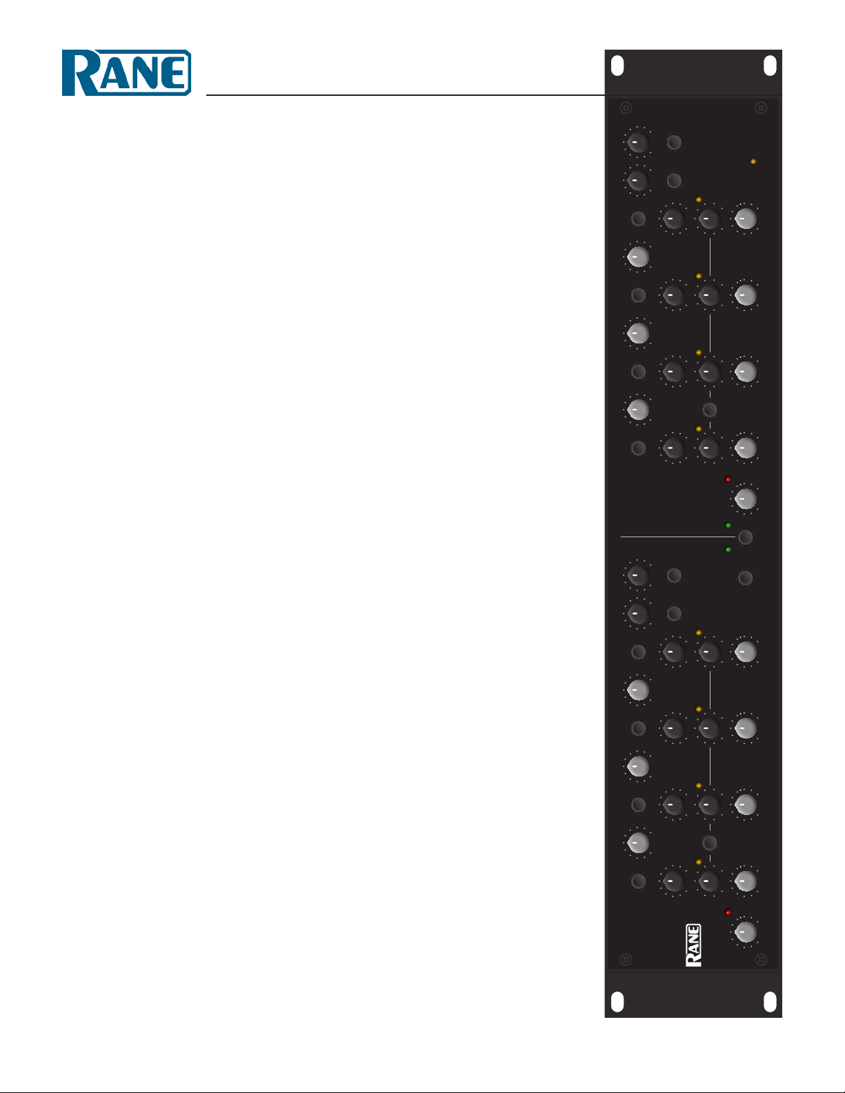
AC 24
CROSSOVER
4
HORN EQ
4
8.0
6.3
5.0
4.0
3.15
2.5
2.0
HI-MID HIGH
1.0k
800
630
500
400
315
250
MIDLOW
200
160
125
100
80
63
50
28
FREQHI-MID HIGH
kHz kHz
28
MUTE
10.0
12.5
kHzHzHz
1.25
1.6
MUTE
1.25k
1.6k
160
200
250
315
FREQ FREQ FREQ
31.5
40
MUTE
B
CHANNEL
4-WAY
0 10 ms
0 10 ms
0 10 ms
0 10 ms
DELAY
DELAY
DELAY
DELAY
4-WAY
AC 24
CROSSOVER
LIMIT
-64 0
LIMIT
-64 0
LIMIT
-64 0
LIMIT
-64 0
INPUT
POWER
LEVEL
LEVEL LEVEL
LEVELLEVEL
OL
0 10 0 10 0 10 0 10 0 10
SLAVE
4
HORN EQ
4
8.0
6.3
5.0
4.0
3.15
2.5
2.0
4-WAY 4-WAY
HI-MID HIGH
1.0k
800
630
500
400
315
250
MID
200
160
125
100
80
63
50
LOW
28
FREQ
kHzkHz
HI-MID HIGH
28
MUTE
10.0
12.5
4-WAY 4-WAY
1.25
1.6
1.25k
1.6k
Hz kHz
160
200
MUTE MUTEMUTE
250
315
Hz
FREQ FREQ FREQ
31.5
40
MUTE
A
CHANNEL
4-WAY
0 10 ms
0 10 ms
0 10 ms
0 10 ms
A
STE
R
M
MONO LOW STEREO LINK
LIMIT
-64 0
-64 0
-64 0
LIMIT
LIMIT
0 10 0 10 0 10
LEVEL
LEVEL LEVEL
DELAY
DELAY
DELAY
LINK LINK
LIMIT
DELAY
LEVELLEVEL
-64 0
OL
INPUT
0 10 0 10
Page 2
RISK OF ELECTRIC SHOCK
DO NOT OPEN
CAUTION
IMPORTANT SAFETY INSTRUCTIONS
1. Read these instructions.
2. Keep these instructions.
3. Heed all warnings.
4. Follow all instructions.
5. Do not use this apparatus near water.
6. Clean only with a dry cloth.
7. Do not block any ventilation openings. Install in accordance with manufacturer’s instructions.
8. Do not install near any heat sources such as radiators, registers, stoves, or other apparatus (including ampliers) that produce heat.
9. Do not defeat the safety purpose of the polarized or grounding-type plug. A polarized plug has two blades with one wider than the other. A grounding-type plug has two blades and a third grounding prong. e wide blade or third prong is provided for your safety. If the provided plug does not
t into your outlet, consult an electrician for replacement of the obsolete outlet.
10. Protect the power cord and plug from being walked on or pinched particularly at plugs, convenience receptacles, and the point where it exits from
the apparatus.
11. Only use attachments and accessories specied by Rane.
12. Use only with the cart, stand, tripod, bracket, or table specied by the manufacturer, or sold with the apparatus. When a cart is used, use caution
when moving the cart/apparatus combination to avoid injury from tip-over.
13. Unplug this apparatus during lightning storms or when unused for long periods of time.
14. Refer all servicing to qualied service personnel. Servicing is required when the apparatus has been damaged in any way, such as power supply
cord or plug is damaged, liquid has been spilled or objects have fallen into the apparatus, the apparatus has been exposed to rain or moisture, does
not operate normally, or has been dropped.
15. e plug on the power cord is the AC mains disconnect device and must remain readily operable. To completely disconnect this apparatus from
the AC mains, disconnect the power supply cord plug from the AC receptacle.
16. is apparatus shall be connected to a mains socket outlet with a protective earthing connection.
17. When permanently connected, an all-pole mains switch with a contact separation of at least 3 mm in each pole shall be incorporated in the electrical installation of the building.
18. If rackmounting, provide adequate ventilation. Equipment may be located above or below this apparatus, but some equipment (like large power
ampliers) may cause an unacceptable amount of hum or may generate too much heat and degrade the performance of this apparatus.
19. is apparatus may be installed in an industry standard equipment rack. Use screws through all mounting holes to provide the best support.
WARNING: To reduce the risk of re or electric shock, do not expose this apparatus to rain or moisture. Apparatus shall not be exposed to dripping
or splashing and no objects lled with liquids, such as vases, shall be placed on the apparatus.
NOTE: is equipment has been tested and found to comply with the limits for a Class B digital device, pursuant to part 15 of the FCC Rules. ese
limits are designed to provide reasonable protection against harmful interference in a residential installation. is equipment generates, uses and can
radiate radio frequency energy and, if not installed and used in accordance with the instructions, may cause harmful interference to radio communications. However, there is no guarantee that interference will not occur in a particular installation. If this equipment does cause harmful interference to
radio or television reception, which can be determined by turning the equipment o and on, the user is encouraged to try to correct the interference
by one or more of the following measures:
• Reorient or relocate the receiving antenna.
• Increase the separation between the equipment and receiver.
• Connect the equipment into an outlet on a circuit dierent from that to which the receiver is connected.
• Consult the dealer or an experienced radio/TV technician for help.
CAU TION: Changes or modications not expressly approved by Rane Corporation could void the user's authority to operate the equipment.
is Class B digital apparatus complies with Canadian ICES-003.
Cet appareil numérique de la classe B est conforme à la norme NMB-003 du Canada.
WARNING
To reduce the risk of electrical shock, do not open the unit. No user
serviceable parts inside. Refer servicing to qualied service personnel.
e symbols shown below are internationally accepted symbols that warn
of potential hazards with electrical products.
is symbol indicates that a dangerous voltage
constituting a risk of electric shock is present within
this unit.
is symbol indicates that there are important
operating and maintenance instructions in the
literature accompanying this unit.
Page 3
OPERATORS MANUAL
AC 24
ACTIVE CROSSOVER
LOW
CHANNEL
0100 10
INPUT
A
0 10 ms
-640
OL
MUTE
DELAY
LIMIT
LEVELLEVEL
MID
100
80
125
63
160
50
200
40
250
MUTE MUTEMUTE
31.5
315
Hz
FREQ FREQ FREQ FREQ
0 10 ms
DELAY
-640
LIMIT
LINK LINK
010010 010
LEVEL LEVEL
HI-MID HIGH
500
400
630
315
800
250
1.0k
200
1.25k
160
1.6k
Hz kHz
4.0
3.15
5.0
4-WAY 4-WAY
2.5
6.3
2.0
8.0
1.6
10.0
MUTE
1.25
12.5
4-WAY 4-WAY
0 10 ms
DELAY
-640
LIMIT
0 10 ms
DELAY
-640
LIMIT
LEVEL
HORN EQ
4
28428
kHzkHz
HI-MID HIGH
4-WAY
MONO LOW STEREO LINK
QUICK START
e AC 24 is fully balanced with XLR connectors wired pin 2
“hot” per AES standards. Set the 3-WAY/4-WAY switch on the
rear appropriately. When in 3-WAY mode, the HI-MID controls
are inactive. e MID / HI-MID Frequency control becomes the
MID / HIGH Frequency control.
If you need a summed Mono Low Ouput, push the MONO
LOW switch on the front panel.
e FREQUENCY controls and other alignment procedures
are best set with a realtime analyzer (RTA). It’s also good to have
range specifications for the drivers used in the system. See Select
Crossover Frequencies on page Manual-4.
e DELAY controls add from 0 to 10 ms of signal delay to
each Output to assist in signal-aligning drivers. See Adjust Signal
Delay on page Manual-5.
CD HORN EQ is provided if constant-directivity horns are
used. If CD Horn EQ is not required, make sure the HORN EQ
filters are off (button out) and frequency settings are at 8 kHz. See
Set CD Horn EQs on page Manual-8.
LEVEL controls are best set using the steps provided in Set
Output Levels on page Manual-8.
e MID, HI-MID and HIGH Output LIMIT reshold
controls are linked to preserve spectral balance. Any Output that
MIDLOW
100
80
125
63
160
50
200
40
CHANNEL
M
S
A
L
S
A
T
V
E
E
R
0100 10 010010 010
INPUT
B
0 10 ms
-640
OL
MUTE
DELAY
LIMIT
LEVELLEVEL
250
31.5
315
FREQ FREQ FREQ
0 10 ms
DELAY
-640
LIMIT
LEVEL LEVEL
500
400
315
250
200
160
HI-MID HIGH
3.15
2.5
2.0
1.6
MUTE
1.25
0 10 ms
DELAY
-640
LIMIT
4.0
kHzHzHz
630
800
1.0k
1.25k
1.6k
5.0
6.3
8.0
10.0
MUTE
12.5
010 ms
DELAY
-640
LIMIT
LEVEL
HORN EQ
4
28428
kHz kHz
FREQ
HI-MID HIGH
4-WAY
AC 24
CROSSOVER
POWER
crosses its threshold (indicated by the indicator) will cause all
Outputs to Limit. e LOW Output is independent, and may be
linked to the others via the LIMIT LINK switch. See Set Limit-
ers on page Manual-9.
When using STEREO LINK, we recommend turning down
the Output Level controls of the SLAVE (Channel B) to mini-
mum. is prevents unwelcome surprises if the Master / Slave
function is turned off.
e SUM Outputs are useful for instrumentation devices as
indicated in the setup procedure. ese may also be used for splitband EQ and/or split-band Limiter applications. When using
these, it is important to note that CD HORN EQ and DELAYS
affect the Summed Output. If you want a flat response, do not use
Delay or CD Horn EQ when using the Sum Outputs.
e INVERT switches located on the rear panel allow you
to correct driver polarity differences without rewiring. LinkwitzRiley filter outputs are always in phase with correct polarity.
In agreement with IEC and AES/ANSI standards, wiring convention is pin 2 positive, pin 3 negative (return), pin 1
shield chassis ground. See the “Sound System Interconnection”
RaneNote included with this manual for more information on
cabling and grounding requirements.
4-WAY
WEAR PARTS: is product contains no wear parts.
Manual-1
Page 4

3 4 3 4 3 4 3 5 6
MUTE MUTE MUTE
FREQ FREQ FREQ
MUTEHI-MID HIGH FREQ FREQ FREQ
3 4 3 4 3 4 3 5 6
MUTE MUTE MUTE
MUTEHI-MID HIGH
LOW
CHANNEL
0100 10
MUTE
A
0 10 ms
DELAY
-640
LIMIT
INPUT
OL
LEVELLEVEL
1 99
DELAY DELAY DELAY DELAY
LEVEL
LIMIT
LEVEL LEVEL LEVEL LEVEL
MID
100
80
125
63
160
50
200
40
250
MUTE MUTEMUTE
31.5
315
Hz
FREQ FREQ FREQ FREQ
0 10 ms
DELAY
-640
LIMIT
LINK LINK
010010 010
LEVEL LEVEL
9 9
8
LIMIT LIMIT LIMIT
LINK
HI-MID HIGH
500
400
630
315
800
250
1.0k
200
1.25k
160
1.6k
Hz kHz
4.0
3.15
5.0
4-WAY 4-WAY
2.5
6.3
2.0
8.0
1.6
10.0
MUTE
1.25
12.5
4-WAY 4-WAY
0 10 ms
DELAY
-640
LIMIT
0 10 ms
DELAY
-640
LIMIT
LEVEL
777 7
222 2
HORN EQ
4
28428
kHzkHz
HI-MID HIGH
4-WAY
M
A
S
T
E
R
MONO LOW STEREO LINK
11 10 1 99
MONO LOW STEREO LINK
CHANNEL
S
L
A
V
E
0100 10 010010 010
MUTE
B
0 10 ms
DELAY
-640
LIMIT
INPUT
OL
LEVELLEVEL
LEVEL
DELAY DELAY DELAY DELAY
LIMIT
LEVEL LEVEL LEVELLEVEL
MIDLOW
100
80
125
63
160
50
200
40
250
31.5
315
FREQ FREQ FREQ
0 10 ms
DELAY
-640
LIMIT
LEVEL LEVEL
500
400
315
250
200
160
HI-MID HIGH
630
800
1.0k
1.25k
MUTE
1.6k
0 10 ms
DELAY
-640
LIMIT
9 9
8
LIMIT LIMIT LIMIT
LINK
777 7
222 2
MUTE
28428
HI-MID HIGH
4-WAY
DELAY
LIMIT
LEVEL
HORN EQ
4
kHz kHz
FREQ
POWER
12
POWER
AC 24
CROSSOVER
4-WAY
4.0
3.15
5.0
2.5
6.3
2.0
8.0
1.6
10.0
1.25
12.5
kHzHzHz
0 10 ms
-64 0
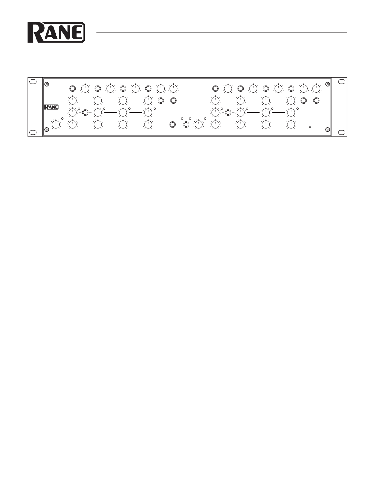
1 Channel INPUT LEVEL controls and OL indicator: Set the overall Levels of Channels A and B without altering the relative
settings of the Low, Mid, Hi-Mid and High frequency Outputs. e range is 80 dB, and maximum gain is 6 dB. e OL warning indicator lights 4 dB before clipping. Audio taper is down 16 dB at the center of rotation (dot 5). Unity gain is the white dot
between dots 7 and 8.
2 Low, Mid, Hi-Mid and High Output LEVEL controls: Sets the signal Level going to each of the Crossover Outputs. e Hi-Mid
control is inactive in 3-Way Mode. Refer to ‘Setting the Output Level Controls’ on page Manual-7. Audio taper is down 16 dB at
the center of rotation (dot 5). Unity gain is the white dot between dots 7 and 8.
3 Low, Mid, Hi-Mid and High Output MUTE switches: When pressed to the in position, all signal is removed from the respective
frequency Output. is eases tune-up procedures as described beginning on page Manual-4.
4 Crossover FREQUENCY controls: Set the crossover frequencies between the Low, Mid, Hi-Mid and High frequency Outputs.
e Hi-Mid control is inactive in 3-Way Mode. Refer to ‘Select Crossover Frequencies’ on page Manual-4.
5 Hi-Mid Output CD HORN EQ and engage switches: When the switch is pressed to the in position, the CD Horn EQ is active
when the AC 24 is in 4-Way mode. If CD Horn EQ is not required, make sure the HORN EQ filters are off and frequency settings
are at 8 kHz. Refer to ‘Set CD Horn EQs’ on page Manual-7.
6 High Output CD HORN EQ and engage switches: When the switch is pressed to the in position, the CD Horn EQ is active. If
CD Horn EQ is not required, make sure the HORN EQ filters are off and frequency settings are at 8 kHz.
7 Output LIMIT controls and indicators: ese are resholds for each of the Output Limiters, with a range of 0 to -64 dBFS. To
maintain spectral accuracy, Mid, Hi-Mid and High frequency Outputs are linked, so that any signal that crosses a reshold will
limit all three Outputs equally (see 8). e independent reshold indicators show which band is the source of the limit condition.
Refer to ‘Setting Limiters’ on page Manual-8.
8 Low Output LIMITER LINK switch: e Limiter for the Low Output is independent of the Mid, Hi-Mid and High frequency
Output Limiters. is is often desirable to prevent “pumping” or modulating higher frequencies. Depressing this switch “links” the
Low Limiter to the other limiters. Refer to ‘Set Limiters’ on page Manual-8.
9 Low, Mid, Hi-Mid and High Output DELAY controls: Add from 0 to 10 ms of signal Delay to each of the Crossover Outputs
(10 ms = 135 inches = 11.313 feet = 3.429 meters). is allows a driver to be electronically phase-aligned with a driver whose diaphragm is situated behind the other. Refer to ‘Adjust Signal Delay’ on page Manual-5.
0 STEREO LINK switch: is switch links CHANNEL A as the MASTER to CHANNEL B as the SLAVE, useful in stereo ap-
plications. In this mode, the MASTER (A) controls all of the SLAVE’s (B) DSP functions, leaving Channel B’s controls inactive.
When using the Stereo Link, we recommend setting the SLAVE (B) Outputs to minimum. is prevents unwelcome surprises if the
STEREO LINK switch is turned off.
q MONO LOW Output switch: Sums the Outputs of Channels A and B, appearing at the Channel A LOW Output.
w POWER indicator: When this yellow LED is lit, you guessed right — the unit is on and ready.
Manual-2
Page 5

8 6 5 4 3 2 8 6 5 4 7 2
AC 24
MADE IN U.S.A.
RANE CORP.
ACN 001 345 482
100-240V
20 WATTS50/60 Hz
SUM HIGH HI-MID MID LOW INPUT
FOR CONTINUED
GROUNDING
PROTECTION
DO NOT REMOVE
SCREW
3-WAY 4-WAY
(HI-MID UNUSED)
4-WAY 4-WAY
COMMERCIAL AUDIO
EQUIPMENT 24TJ
R
INVERTINVERTINVERT
INVERT INVERT INVERT INVERT INVERT
CHANNEL
B
SUM HIGH HI-MID MID LOW
MONO LOW
This device complies with Part 15 of the FCC Rules. Operation is
subject to the following two conditions: (1) this device may not cause
harmful interference, and (2) this device must accept any interference
received, including interference that may cause undesired operation.
INPUT
CHANNEL
A
WIRING
PIN 2 = POSITIVE
PIN 3 = NEGATIVE
PIN 1 = CHASSIS GROUND
1 910 9
1 3-WAY / 4-WAY switch: Converts the outputs from 3-Way to 4-Way. is switch removes the Hi-Mid frequency crossover from
the signal path — the HI-MID / HIGH Frequency control and all HI-MID controls are disabled. e MID / HI-MID Frequency
control becomes the MID / HIGH Frequency control.
2 CHANNEL A and B INPUTS: Plug the outputs of the mixer, equalizer or other source to these Inputs.*
3 LOW Outputs: Connect the CHANNEL A LOW Output to the left channel input of the low frequency amplifier, and the
CHANNEL B LOW Output to the right channel input of the low amplifier. If you need a summed Mono Low Output, use the
CHANNEL A Output (see 7).*
4 MID Outputs: Connect the CHANNEL A MID Output to the left channel input of the amplifier, and the CHANNEL B Mid
Output to the right channel input of the amplifier.*
5 HI-MID Outputs: Are only used in 4-WAY mode. Connect the CHANNEL A HI-MID Output to the left channel input of the
amplifier, and the CHANNEL B HI-MID Output to the right channel input of the amplifier.*
6 HIGH Outputs: Connect the CHANNEL A HIGH Output to the left channel input of the high frequency amp, and the CHAN-
NEL B HIGH Output to the right channel input of the high frequency amp.*
7 CHANNEL A LOW Output: Connect this Output to the input of the low frequency amplifier when the MONO LOW switch is
activated on the front panel. It contains the sum of both CHANNEL A and B LOW signals.*
8 SUM Outputs: Are a sum of the LOW, MID, HI-MID, and HIGH Outputs. e Sum Outputs are useful to connect to instru-
mentation devices as indicated in the setup procedure. Use the Sum Outputs for split-band EQ and/or split-band Limiter applications. When using the Sum Outputs, it is important to note that CD Horn EQ and Delays affect the summed output. If you want a
flat response, do not use delay or CD Horn EQ when using these Sum Outputs.*
9 Output INVERT switches: may assist in keeping drivers in-phase without having to rewire connections. Linkwitz-Riley filter Out-
puts are always in phase with correct polarity. Be sure the amplifiers are off before changing any of these switches.
0 Power connector: Uses the standard cord provided. Inside the AC 24 is a universal internal switching power supply that accepts
100 to 240 VAC at 50 to 60 Hz, allowing it to work in most countries.
*Note: In agreement with IEC and AES/ANSI standards, wiring convention is pin 2 positive, pin 3 is negative (return), pin 1 is shield chassis
ground.
Manual-3
Page 6

Setup Methods
e goal is to design a 3-way or 4-way system with the flattest
possible response and good dispersion. Two practical methods for
crossover setup follow:
1. Use relatively low levels of pink noise and close microphone
placement (18 to 36 inches)[45 to 90 cm] to minimize the
effects of room acoustics. Once the system is tuned, lock the
crossover behind a security cover.
2. Use measurement tools designed to analyze installed systems. Professional system analysis tools are available that can
discriminate between room acoustics and system response.
SIA Software Company, Inc., have developed tools, including
SmaartLive and SIA Acoustic Tools, that allow sound system
measurement and acoustic analysis. e software is designed
for serious pro audio and acoustical consultant engineers. For
more information visit www.siasoft.com. Once the system is
tuned, lock the crossover behind a security cover.
Setup Instructions
e following crossover setup procedure is based on the use of
close microphone placement with the system installed. e procedure requires a real-time analyzer, pink noise source and SPL
meter. ere are five steps:
STEP ONE: Select Crossover Frequencies
STEP TWO: Adjust Signal Delay
STEP THREE: Set CD Horn EQs (if required)
STEP FOUR: Set Output Levels
STEP FIVE: Set Limiters
Note: If you are running two Channels, tune up only one Chan-
nel at a time, unless the STEREO LINK is used.
STEP ONE: Select Crossover
Frequencies
Most speaker manufacturers supply low and high frequency cutoff points for each driver. ese cut-off frequencies are based on
each driver’s response limitations, physical limits and safe operating area. Most specifications allow a safety margin to accommodate gentler filter roll-off.
e AC 24 utilizes continuously adjustable frequency selectors. Each precision potentiometer provides 64 steps covering 3.3
octaves (.05 octave per step). is resolution assures consistent
accuracy.
e AC 24 possesses 24 dB per octave roll-off, so the crossover points are easily set with the accuracy required to avoid
hazard to the driver or degradation in sound quality.
For best results, choose speaker components so each operates well within its recommended limits with adequate response
overlap. is provides valuable leeway in crossover frequency settings and helps ensure the flattest possible system response. Extra
margin also yields higher system reliability. If possible, always use
some kind of realtime analyzer to tune your crossover.
Low pass 100 Hz 500 Hz 4 kHz
0 dB
Amplitude (dB)
Low / Mid Mid / Hi-Mid Hi-Mid / High
Mid frequency Hi-Mid frequency
Frequency (Hz)
s
l
o
p
e
= n d
B
/
octave
s
l
o
p
High pass
e
= n d
B
/
octave
Figure 1. Driver responses and crossover points
Figure 1 shows typical driver responses for a 4-way system and
the selected crossover frequencies. Select each drivers response
and set each crossover frequency to allow significant overlap in
response.
After Crossover Frequency settings are made based on driver
data, the best way to proceed is with a realtime analyzer. is
allows verification of crossover settings and adjustment of output
levels to compensate for the sensitivity of individual drivers.
STEP TWO: Adjust Signal Delay
Before jumping feet first into the realm of signal delay compensation, it helps to re-affirm why delay is necessary. For a short
course on signal delay and Linkwitz-Riley crossovers, we recommend the “Linkwitz-Riley Crossovers” RaneNote. Ask your
dealer, call us at the factory, or get it from our website.
Let’s review the basic effects of signal delay in crossovers.
Problems pop up when two different speakers emit the same
frequency in the crossover regions. Because the two drivers are
displaced vertically, cancellation occurs somewhere off-axis because the sound waves have to travel different distances from the
two speakers and hence, arrive out of phase. is forms a “lobe”
or radiation pattern, narrowing the listening-area of the speaker.
Fine, so we put up with it.
To make matters worse, when two drivers are horizontally
displaced—that is, one is in front of or behind the other, this
“lobe” or dispersion pattern gets tilted toward the driver that is
further behind (see Figure 2). e result is a speaker system with
two, three, four or more tilted radiation patterns.
In an ideal system, all drivers are aligned in the same vertical
plane and all components are in phase. With main lobes on-axis
and well behaved, the system has the widest possible dispersion
pattern and everyone gets good sound. Unfortunately, it’s often
physically impossible to place all the driver sound sources in the
same vertical plane. Fortunately, by electronically delaying the
signal going to the front driver, the sound from the rear driver is
able to catch up. e result is signals from both drivers arriving in
phase with correct acoustic summing (see Figure 3).
e trick is finding the proper signal delay amount: hence the
rest of this section. It is possible to get good results by setting the
required signal delay based exclusively on horizontal displacement
as outlined in Signal Delay Method One. Ideally, using true
delay in combination with phase compensated crossover filters,
would make the required signal delay independent of the crossover
frequency. If true, the required delay could be determined solely
by the horizontal displacement between driver voice coils. e
world is seldom ideal. e drivers themselves introduce phase shift
that must be accounted for. erefore, best results are achieved by
calibrating the required delay outlined in Signal Delay Method
Two.
Manual-4
Page 7

• is allows delay compensation for distances ranging from 0.0
to 135 inches (11.3 feet) [343 cm].
• e resolution of the adjustment is about 0.6 inch [1.5 cm].
Important Note: e horizontal location of a driver is deter-
mined by the front of the voice coil.
Method One, Step-by-Step
1. Identify the driver that is the furthest away from the front of
the stack. is driver gets zero delay. e horizontal displacement of all other drivers is measured relative to this driver.
2. Take the distance, measured in inches, for each driver and divide
by 13.57. is gives the delay in milliseconds and pot rotation
in “fractional-dots.” See Figure 4.
Fig. 2 In-Phase Axis Response Without Signal Delay
Fig. 3 Corrected In-Phase Axis Response with Delay on Low Driver
Signal Delay Adjustment Method One
If you can not get your hands on the equipment necessary to
electronically align the system, it is possible to set the delays using
only the horizontal displacement of the sound sources. It is very
important to make certain that all drivers have correct polarity before
setting signal alignment delay. First, let’s review the basic informa-
tion required for the task.
• e general equation for the speed of sound in dry air is:
331.4+0.6Tc m/s
Tc = temperature in degrees Celsius,
m = meters and
s = seconds
• For those still having diculty accepting the metric system, the
following approximation will do:
13.57 inches / millisecond at 72° Fahrenheit.
34.5 cm / millisecond at 22° Celsius.
• e AC 24 provides 10 ms of delay. Each dot on the silkscreen
represents 1 ms or 13.57 inches (at 72 °F).
Signal Delay Adjustment Method Two
OK, so you want to do this the hard way. e following example
outlines one method for Signal Delay alignment of the system in
Figure 4. e procedure easily adapts to other configurations.
Required tools: Realtime Analyzer
th
Cautions/considerations: With 4
-order filters, it’s important to accurately identify crossover frequency settings before
adjusting delay. A reference level must be set for each driver at
each crossover point. is eliminates errors due to non-flat driver
response and room acoustics. When using a ⅓-octave realtime ana-
lyzer, best results are achieved if crossover points are set to the nearest
⅓-octave center.
Method Two, Step-by-Step
1. Initial AC 24 control settings:
a. Leave FREQUENCY controls as set in Step One.
b. MUTE all Outputs.
c. Set Input and Output LEVEL controls to unity (the mark
th
between the 8
and 9th dots).
d. Set DELAYS to zero.
e. Switch CD HORN EQs off.
f. Set LIMITERS to 0 dB FS.
g. Set all rear INVERT switches to the out (non-inverting)
position (assuming all drivers are in phase).
2. Connect the RTA to the AC 24:
a. Connect Pink Noise output to Crossover Input.
b. Connect AC 24 Sum Output to RTA Line Input.
c. Set RTA Scale to 3 dB if available.
d. Turn on Pink Noise.
3. Adjust crossover frequencies to ISO centers:
a. For this crossover frequency calibration you are looking at
the line level Sum output and NOT the acoustic output.
b. Amplifiers off.
c. UnMUTE the AC 24 Low Output.
i) e 1st 6 dB red LED on the RTA indicates the
Low / Mid crossover frequency.
ii) Adjust the LOW / MID Frequency to just light the
1st –6 dB red LED closest to the desired crossover
frequency.
Manual-5
Page 8

iii) Record the Low / Mid crossover frequency.
iv) MUTE the AC 24 Low Output.
d. Unmute AC 24 Hi-Mid output.
i) e 1st low-side –6 dB red LED on the RTA
indicates the Mid / Hi-Mid crossover frequency.
ii) Adjust the MID / HI-MID Frequency to just light
the 1st low-side –6 dB red LED closest to the desired
crossover frequency.
iii) Record the Mid / Hi-Mid crossover frequency.
iv) e 1st high-side –6 dB red LED on the RTA
indicates the Hi-Mid / High crossover frequency.
v) Adjust the HI-MID / HIGH Frequency to just
light the 1st high-side red LED closest to the desired
crossover frequency.
vii) Note the Hi-Mid / High crossover frequency.
e. MUTE all AC 24 Outputs.
f. Set All AC 24 Output LEVEL controls to minimum.
4. Connect the Crossover to the Amplifiers:
a. Amplifiers off.
b. Connect Crossover Outputs to appropriate amplifiers.
c. If you have gain controls on your amps, set these for the
desired sensitivity (input voltage required to clip the amp).
1
d. Do not adjust amplifier sensitivity controls after you have
set crossover Output Levels.
e. Place the RTA microphone about 24 inches [60 cm] away
from the speaker stack, as close to equidistant to each driver
as possible (see Figure 4).
f. Set the RTA scale to 1 dB if available.
i. Turn on the RTA Pink Noise.
j. Turn on the amplifiers.
24"
(61 cm)
HIGH = 1.14 ms DELAY
0 10 ms
0 10 ms
0 10 ms
mic
POSITION 1
HI-MID = 0 ms DELAY
POSITION 2
mic
MID = 0.81 ms DELAY
mic
POSITION 3
5. Set the Delays starting with the driver furthest back (the one
that gets zero delay) and work outward (see Figure 4).
6. Hi-Mid / High Delay alignment:
a. Place the RTA mic in Position 1 as shown in Figure 4.
b. Set reference level for AC 24 High Output:
i) UnMUTE the High Output.
ii) Adjust the High Output LEVEL control so that an
adequate pink noise level is present.
iii) Adjust the High Output LEVEL so the RTA LED,
at the Hi-Mid / High crossover frequency, is green.
iv) MUTE the High Output.
c. Set reference level for AC 24 Hi-Mid Output:
i) UnMUTE the Hi-Mid Output.
ii) Adjust the Hi-Mid Output LEVEL so the RTA LED,
at the Hi-Mid / High crossover frequency, is green.
d. Set the High Output DELAY:
i) Referring to Figure 4, note the Hi-Mid Output is the
furthest back and requires no delay.
ii) UnMUTE the Hi-Mid and High Outputs.
iii) If the level goes down, driver polarity may be wrong.
Check the driver polarity before proceeding.
iv) Adjust the High Output DELAY for maximum
signal level in the RTA band associated with the
Hi-Mid / High crossover frequency.
7. Mid / Hi-Mid Delay alignment:
a. Place the RTA mic in Position 2 as shown in Figure 4.
b. Set the reference level for Hi-Mid Output:
i) UnMUTE the Hi-Mid Output.
ii) Adjust the Hi-Mid Output LEVEL so the RTA LED,
associated with the Mid / Hi-Mid crossover frequency,
is green.
iii) MUTE the Hi-Mid Output.
c. Set the reference level for the Mid Output:
i) UnMUTE the Mid Output.
ii) Adjust AC 24 Mid Output Level so the RTA LED,
associated with the Mid / Hi-Mid crossover frequency,
is green.
d. Set Mid Output Delay:
i) Referring to Figure 4, note that the Hi-Mid Output
is the furthest back and requires no delay.
ii) UnMUTE the Mid and Hi-Mid Outputs.
iii) If the level goes down, driver polarity may be
wrong. Check the driver polarity before proceeding.
iv) Adjust the Mid Output Delay for maximum signal
level in the RTA band associated with the Mid / Hi-Mid
crossover frequency.
LOW = 0.663 ms DELAY
0 10 ms
9"
(22.9 cm)
11"
(27.94 cm)
15.5"
(39.4 cm)
Figure 4. Delay setttings calculated using furthest driver as zero.
Manual-6
8. Low / Mid Delay alignment:
a. Place the RTA mic in Position 3 as shown in Figure 4.
b. Set the reference level for the Mid Output:
i) UnMUTE the Mid Output.
ii) Adjust the Mid Output LEVEL so the RTA LED
associated with the Low / Mid crossover frequency is
green.
iii) MUTE the Mid Output.
Page 9

c. Set the reference level for the Low Output:
i) UnMUTE the Low Output.
ii) Adjust the Low Output LEVEL so the RTA LED
associated with the Low / Mid crossover frequency, is
green.
d. Set the Low Output Delay:
i) e Mid Output Delay was previously set and must
not be changed.
ii) UnMUTE the Low and Mid Outputs.
iii) If the level goes down, driver polarity may be wrong.
Check the driver polarity before proceeding.
iv) Adjust the Low Output Delay for maximum
signal level in the RTA band associated with the
Low / Mid crossover frequency.
STEP FOUR: Set Output Levels
1. Set all AC 24 Output LEVEL controls to minimum.
2. MUTE all AC 24 Outputs.
3. Set the INPUT LEVEL controls at unity (white dot between 7
4. Realtime Analyzer setup:
& 8).
a. Place the RTA mic on axis, 1 meter away from
the Low driver as shown in Figure 5, Position-1.
b. Set RTA Scale to 3 dB, if available.
c. Turn on Pink Noise.
STEP THREE: Set CD Horn EQs
(if required)
Constant Directivity (CD) Horns need additional equalization to
help cover the same area as a long-throw horn. e
AC 24 has independent CD Horn EQ circuits for Hi-Mid and
High Outputs. It is important to know the 3 dB down point of
the CD Horn driver’s frequency response. e manufacturer of
your driver can supply you with a response curve.
NOTE: If CD Horn EQ is not required, make sure the HORN EQ
filters are OFF and frequency settings are at 8 kHz.
1. Find the frequency where the high end starts to roll off, and
look for the frequency on the chart that has an amplitude 3 dB
down from that point (toward the right, as the higher frequencies roll off).
2. Set the CD Horn EQ frequency to the frequency that corresponds to the 3 dB down point indicated on the graph and
engage the filter. (an approximate is fine, it doesn’t have to be
exact)
5. Set the Low Output Level:
a. UnMUTE the Low Output and slowly turn up the LOW
LEVEL control until you hear a healthy level of noise
through the low frequency drivers (sounds like rumble).
b. Adjust the LOW LEVEL to light the most 0 dB LEDs
in the Low frequency passband.
c. MUTE the Low Output.
6. Set the Mid Output Level:
a. Move the RTA mic to Position 2.
b. Without adjusting the realtime analyzer, UnMUTE the
Mid Output and adjust the MID LEVEL control to light
the most 0 dB LEDs in the Mid output passband.
c. MUTE the Mid Output.
7. Set the Hi-Mid Output Level:
a. Move the RTA mic to Position 3.
b. Without adjusting the realtime analyzer, UnMUTE the
Hi-Mid Output and adjust the HI-MID LEVEL control to
light the most 0 dB LEDs in the Hi-Mid output passband.
c. MUTE the Hi-Mid Output.
8. Set High Output Level:
a. Move the RTA mic to Position 4.
b. Without adjusting the realtime analyzer, UnMUTE the
High Output and adjust the HIGH LEVEL control to light
the most 0 dB LEDs in the High output passband.
c. MUTE the High Output.
1
Note: Contrary to popular belief, dynamic headroom is optimized by setting amplifier sensitivity so that the amplifier clips at the same point
the signal processing clips (typically +20 dBu to +24 dBu). For example, if the noise floor is –80 dBu and the maximum signal level is +20
dBu, then the dynamic range is 100 dB. If the amplifier is set to clip at +4 dBu, then the dynamic range is 84 dB. Or, 16 dB worse!
Manual-7
Page 10

39.4"
POSITION 4
POSITION 1
POSITION 2
POSITION 3
(1 meter)
mic
mic
6. Realtime Analyzer setup:
a. Place the RTA mic on axis, 1 meter away from
the Low driver as shown in Figure 5, Position 1.
b. Set the RTA SPL Filter to C-Weighting.
c. Turn on the Pink Noise.
7. Make sure the Pink Noise Level coming into the crossover is
able to light the red OL indicator.
mic
mic
Figure 5. Setting Output Levels with a calibrated mic.
STEP FIVE: Setting Limiters
Each AC 24 Crossover Output has a Limiter. Each Limiter has an
independent reshold control with a range of 0 dB FS to –64
dB FS. To maintain spectral accuracy, Mid, Hi-Mid and High
Limiters are linked. Linking is accomplished with wired-or control. ese outputs all receive the same gain reduction regardless
of which one initiates limiting. Independent reshold indicators
show which band is the source of the limit condition. e Low
Output Limiter may operate independently. is is often desirable to prevent “pumping” or modulating higher frequencies. If
desired, there is a Low Limit Link switch.
Method One: Driver SPL.
1. Do not change any of the previously calibrated AC 24 Output
Level controls.
2. Do not change any amplifier gain controls.
3. MUTE all AC 24 Outputs.
4. Set all LIMIT controls to –64.
5. Determine the maximum SPL for each driver.
a. Find the manufacturers sensitivity rating
(dB SPL @ 1 watt, @ 1 meter ) = dB SPL
b. Find the manufacturers maximum continuous power
rating (P
c. SPL
MAX
= dB SPL
MAX
)
+ [10*Log(P
REF
)]
MAX
REF
8. Set SPL
for each driver (one Output at a time):
MAX
a. Depending on the maximum safe SPL rating of your
system, you may want to use ear protection.
b. Place the RTA mic on axis at 1 meter (see Figure 5).
c. UnMUTE the AC 24 Output associated with the driver
you are setting the Limiter for.
d. Slowly increase the LIMIT reshold until the RTA SPL
meter reads the SPL
calculated in step 4 for the driver
MAX
you are setting the Limiter for.
e. MUTE the associated AC 24 Output.
f. Repeat for each driver.
Method Two: Voltage at the driver.
Method Two uses the voltage at the driver instead of the SPL.
Using voltage is not as desirable as SPL because impedance often
varies with frequencies. Manufacturers provide the maximum
recommended continuous power (P) and Nominal Impedance
(R) ratings for each Driver. e maximum voltage is calculated as
follows:
• V
= √(P*R)
MAX
P = Maximum Power
R = Nominal Impedance
• Calculate V
for each driver.
MAX
• Follow the steps outlined above for setting Limiters using SPL.
Simply substitute volt meter readings for RTA SPL readings.
System calibration is complete!
We highly recommend installing the included security
cover As Soon As Possible!
Fix-lt-With-The-Crossover School
Consider the following (now that you have worked so hard to
accurately set up the crossover). Some maintain that a good active
crossover can work alone like a parametric equalizer in the hands
of an expert. is does require experience, skill, and the right
equipment to back it up (not to mention a licensed set of ears).
Regardless of which school you profess, the absolute importance
and effectiveness of some kind of realtime analyzer in your system
cannot be overstressed! Analyzers in general have come a long
way. An analyzer saves tremendous amounts of time and provide
the absolute consistency, accuracy, and plain old good sound that
few ears on this earth can deliver. You’ll wonder how you managed without one.
©Rane Corporation 10802 47th Ave. W., Mukilteo WA 98275-5098 USA TEL 425-355-6000 FAX 425-347-7757 WEB www.rane.com
Manual-8
106220
 Loading...