

Page 1
OPERATING, SERVICE AND
MAINTENANCE MANUAL
MODEL SCH 6000
PLANETARY WINCH
CAUTION: READ AND UNDERSTAND THIS MANUAL BEFORE INSTALLATION AND
OPERATION OF WINCH. SEE WARNINGS!
Page 2

TABLE OF CONTENTS
INTRODUCTIONS . . . . . . . . . . . . . . . . . . . . . . . . . . . . . . . . . . . . . . . . . . . . . . . . . . . . . . . . . . . . . . . .1
WARRANTY INFORMATION . . . . . . . . . . . . . . . . . . . . . . . . . . . . . . . . . . . . . . . . . . . . . . . . . . . . . . . .1
SPECIFICATIONS . . . . . . . . . . . . . . . . . . . . . . . . . . . . . . . . . . . . . . . . . . . . . . . . . . . . . . . . . . . . . . . .1
WARNINGS . . . . . . . . . . . . . . . . . . . . . . . . . . . . . . . . . . . . . . . . . . . . . . . . . . . . . . . . . . . . . . . . . . . .1
HYDRAULIC SYSTEM REQUIREMENTS . . . . . . . . . . . . . . . . . . . . . . . . . . . . . . . . . . . . . . . . . . . . . . .2
PERFORMANCE CHARTS . . . . . . . . . . . . . . . . . . . . . . . . . . . . . . . . . . . . . . . . . . . . . . . . . . . . . . . . .2
WINCH MOUNTING . . . . . . . . . . . . . . . . . . . . . . . . . . . . . . . . . . . . . . . . . . . . . . . . . . . . . . . . . . . . . .3
OPERATIONS . . . . . . . . . . . . . . . . . . . . . . . . . . . . . . . . . . . . . . . . . . . . . . . . . . . . . . . . . . . . . . . . . . .3
MAINTENANCE . . . . . . . . . . . . . . . . . . . . . . . . . . . . . . . . . . . . . . . . . . . . . . . . . . . . . . . . . . . . . . . . .3
CABLE INSTALLATION . . . . . . . . . . . . . . . . . . . . . . . . . . . . . . . . . . . . . . . . . . . . . . . . . . . . . . . . . . . .3
TROUBLE SHOOTING GUIDE . . . . . . . . . . . . . . . . . . . . . . . . . . . . . . . . . . . . . . . . . . . . . . . . . . . . . . .4
DIMENSIONAL DRAWINGS . . . . . . . . . . . . . . . . . . . . . . . . . . . . . . . . . . . . . . . . . . . . . . . . . . . . . . . .5
PARTS LIST AND PARTS DRAWINGS . . . . . . . . . . . . . . . . . . . . . . . . . . . . . . . . . . . . . . . . . . . . . . .6-7
LIMITED WARRANTY . . . . . . . . . . . . . . . . . . . . . . . . . . . . . . . . . . . . . . . . . . . . . . . . . . .BACK COVER
Page 3

PLEASE READ THIS MANUAL CAREFULLY
This manual contains useful ideas for obtaining the most efficient operation from your Ramsey Winch, and safety procedures
one needs to know before operating a Ramsey Winch. Do not operate this winch until you have carefully read and understand
the "WARNING" and "OPERATION" sections of this manual.
WARRANTY INFORMATION
Ramsey Winches are designed and built to exacting specifications. Great care and skill go into every winch we make. If the
need should arise, warranty procedure is outlined on the back of your self-addressed postage paid warranty card. Please read
and fill out the enclosed warranty card and send it to Ramsey Winch Company. If you have any problems with your winch,
please follow instructions for prompt service on all warranty claims. Refer to back page for limited warranty.
SPECIFICATIONS*
* These specifications are based on recommended 7/16 in. (11 mm) EIPS wire rope.
NOTE: The rated line pulls shown are for the winch only. Consult the wire rope manufacturer for wire rope ratings.
WARNINGS:
STAY OUT FROM UNDER AND AWAY FROM RAISED LOADS.
STAND CLEAR OF CABLE WHILE PULLING. DO NOT TRY TO GUIDE CABLE.
DO NOT EXCEED MAXIMUM LINE PULL RATINGS SHOWN IN TABLE.
DO NOT USE WINCH TO LIFT, SUPPORT, OR OTHERWISE TRANSPORT PERSONNEL.
A MINIMUM OF 5 WRAPS OF WIRE ROPE AROUND DRUM BARREL IS REQUIRED TO HOLD THE LOAD.
SCH 6000
Rated Line Pull (lbs) . . . . . . . . . . . . . . . . . . . . . . . . . . . 6,000
(kg) . . . . . . . . . . . . . . . . . . . . . . . . . . . .2,720
Gear Reduction . . . . . . . . . . . . . . . . . . . . . . . . . . . . . . . . . .7.7:1
Weight (without cable) . . . . . . . . . . . . . . . . . . .275 lbs. (125 kg)
LAYER OF CABLE 1 2 3 4
Rated Line Pull
per Layer
lbs 6000 5400 4900 4500
kg 2720 2440 2220 2040
Line Speed
at 8 GPM
fpm 54 58 63 68
mpm 16.4 17.6 19.2 19.4
Cable Capacity ft 25 55 85 120
m 7 16 25 36
1
Page 4
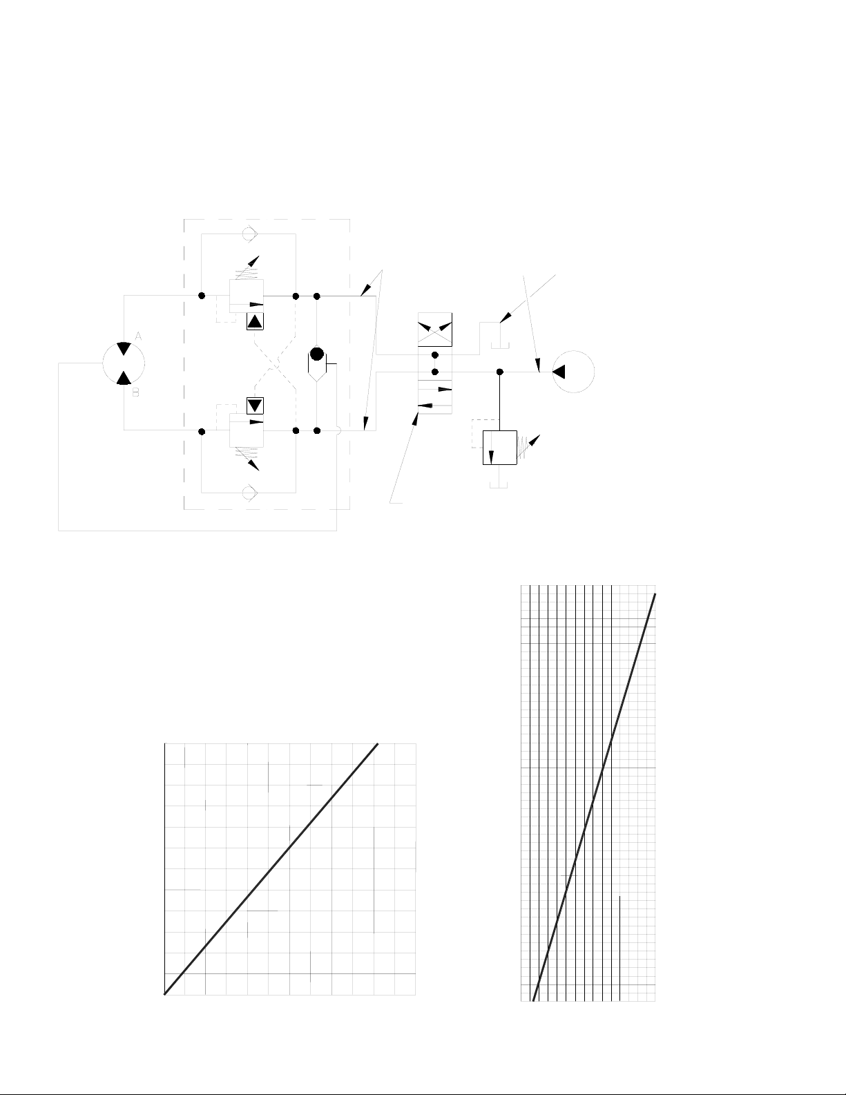
HYDRAULIC SYSTEM REQUIREMENTS
Refer to the performance charts below to properly match your hydraulic system to the winch performance. The
charts consist of: (1) first layer line pull (LB) vs. working pressure (PSI) and (2) first layer line speed (FPM) vs.
flow (GPM). A motor spool directional control valve is required.
TYPICAL LAYOUT
PUMP
(.75 I.D. MINIMUM)
LOW PRESSURE LINE
(.50 I.D. MINIMUM)
HIGH PRESSURE LINE
2100 PSI
15 GPM
RATED LOAD:
PRESSURE AT
MAX. FLOW &
(MOTOR SPOOL)
4 WAY VALVE
3 POSITION
RELIEF
SYSTEM
PORT
BRAKE
MOTOR
WITH BRAKE RELEASE SHUTTLE
DUAL-A & B PORT CONTROL
15
10
0
5
FLOW (GPM)
4,000
3,000
5
800
1,200
2,000
1,000
400
0
0
WORKING PRESSURE, PSI
LINE SPEED-FIRST LAYER (FPM)
LINE PULL-FIRST LAYER (LB.)
15
10
35
20
25
30
2,000 2,400
6,000
55
50
40
45
5,000
1,600
2
PERFORMANCE CHARTS
14.9 cu. in. motor
Page 5

WINCH MOUNTING
NOTE: The winch must be mounted so that it reels in in the required direction as noted on page 5.
NOTE: Remove and discard the (4) 5/8” capscrews from the foot mounting holes in the end bearings.
These capscrews hold on the foot mount spacers during shipping and should not be used for mounting.
It is most important that this winch be mounted securely so that the three major sections (the motor end, the cable
drum, and the gear-housing end) are properly aligned. Excessive bushing wear is a symptom of misalignment.
When installed mid-mounted, at least one tie plate should be attached to the mounting feet at the bottom of the winch
to maintain alignment. When installed foot-mounted, at least one tie plate should remain mounted at mid point of
winch to maintain alignment. It is always preferable to use both tie plates in the installed configuration.
When mounting the winch, the mounting hole patterns described on page 5 should be used. The mounting surface
must be flat within 0.015 inch and sufficiently stiff to resist flexing. If a steel plate is used for foot mounting it should
be .750 inch thick. For this mounting application eight (8) 5/8-11NC x 2” Lg. Gr. 5 capscrews with lockwashers will
be needed to mount winch. Note that the supplied foot-mount spacers (.50” thick) must be installed between the
winch and the mounting plate. Capscrews should be torqued to 173 ft-lb. (235 Nm).
CAUTION: IF LONGER BOLTS ARE SUBSTITUTED TO MOUNT WINCH OR TO MOUNT A ROLLER GUIDE AT
THE SIDE MOUNT PADS, GRADE 5 OR BETTER BOLTS SHOULD ALWAYS BE USED, AND BOLT LENGTH
SHOULD BE SUCH THAT A MAXIMUM OF .56 INCH THREAD LENGTH ENGAGEMENT IS ACHIEVED IN THE
TAPPED HOLES IN THE SIDES OF EACH END BEARING.
OPERATION
The best way to get acquainted with how your winch operates is to make test runs before you actually use it. Plan
your test in advance. Remember, you hear your winch, as well as see it operate. Get to recognize the sounds of a
light steady pull, a heavy pull, and sounds caused by load jerking or shifting. Avoid conditions where load shifts or
jerks occur, as they may indicate a dangerous situation.
The uneven spooling of cable, while pulling a load, is not a problem, unless there is a cable pileup on one end of
drum. If this happens, reverse the winch to relieve the load and move your anchor point further to the center of the
load. After the job is done you can unspool and rewind for a neat lay of the cable.
MAINTENANCE
1. Inspect the cable for damage and lubricate frequently. If the cable becomes frayed with broken strands, replace
immediately.
2. Replace drum bushings and seals when seals begin to seep grease. Add additional lubricant, Mobilith SHC 007,
to gears if required.
CABLE INSTALLATION
1. Unwind cable by rolling it out along the ground to prevent kinking. Securely wrap end of cable, opposite hook,
with plastic or similar tape to prevent fraying.
2. Place taped end of cable into narrow side of pocket on the cable drum. Wrap end of cable around cable anchor
or puck and pull tight.
3. Carefully run winch in the "reel-in" direction. Keeping tension on end of cable, spool all the cable onto the cable
drum, taking care to form neatly wrapped layers.
3
Page 6

CONDITIONS POSSIBLE CAUSE CORRECTION/ACTION
DRUM WILL NOT ROTATE AT NO
LOAD
Brake damaged Inspect and replace brake
Gears damaged Inspect and replace damaged gears
Brake not releasing Brake damaged; inspect and replace.
DRUM WILL NOT ROTATE UNDER
LOAD
Load greater than rated capacity of
winch
Refer to Specifications page 1 for line
pull rating
Low hydraulic system pressure Check pressure. Refer to Hydraulic
Systems performance charts page 2
WINCH RUNS TOO SLOW Low hydraulic system flow rate Check flow rate. Refer to Typical
Layout page 2
Motor worn out Replace motor
BRAKE WILL NOT RELEASE Brake damaged Inspect and replace
EXCESSIVE NOISE Hydraulic system flow too high Check flow rate. Refer to Typical
Layout page 2
DRUM CHATTERS IN “REEL IN”
DIRECTION
Low hydraulic system flow rate Check flow rate. Refer to Typical
Layout page 2
Low hydraulic system relief pressure
setting
Check relief valve setting.
OIL SEEPAGE FROM BREATHER
VENT OF BRAKE HOUSING
Brake piston not sealing properly Replace o-ring and backup o-rings on
brake piston
TROUBLESHOOTING GUIDE
4
Page 7

REEL IN DIRECTION
DIMENSIONS SHOWN ARE INCHES OVER MILLIMETERS
A-A
MOTOR CONTROL VALVE DETAIL
WINCH
VIEW
PRESSURE IN GIVES CLOCKWISE DRUM
ROTATION VIEWED FROM MOTOR END
17,1
.675
PRESSURE IN GIVES COUNTER-CLOCKWISE DRUM
ROTATION VIEWED FROM MOTOR END
7/8-14 SAE STRAIGHT THREAD
O-RING PORT (2-PLACES)
19,8
.781
WINCH MOUNTING CAPSCREWS MUST MEET OR EXCEED SAE GRADE 5 SPECIFICATION
NOTE: THESE HOLE LOCATIONS MUST BE HELD WITHIN ±.03" (0,8 MM) OF
TRUE POSITION. RECOMMENDED MOUNTING HOLE DIAMETER IS .53" (13,5 MM).
(TYP) (TYP)
SPACER
12,7
(TYP)
5/8-11UNC-2B x .88" (22,4MM)
DEEP TAPPED HOLE 4-PLACES
EACH END BEARING
8.48
215,4
22.22
564,5
6.17
156,7
5.70
144,7
3.10
78,7
4.55
115,5
7.50
BARREL DIA.
6.20
157,4
190,5
12.00
304,8
FLANGE DIA.
3.44
87,4
1.38
35,1
12.25
311,1
6.25
158,7
13.65
346,7
6.83
173,4
DRUM
4.23
107,4
.50
SCH 6000
5
Page 8

22
24
23
26
41
49
21
5
43
32
12
19
3
1
14
35
15
53
52
36
11
10
50
7
4
8
38
18
40
37
7
13
45
2
42
46
29
51
34
20
20
25
31
27
28
48
16
25
46
28
17
6
47
39
30
33
MODEL SCH-6000
WITH BLOCKED CLUTCH
44
18
9
8
6
Page 9

Item Quantity Part No. Description Item Quantity Part No. Description
1 1 234195 DRUM ASSEMBLY 27 1 431015 COUPLING-MOTOR
2 1 306042 PISTON-BRAKE 28 2 432018 FITTING
3 1 315004 ANCHOR- CABLE 29 4 438022 DISC-BRAKE
4 1 338345 END BEARING-MOTOR END 30 1 442220 GASKET-BRAKE HSG.
5 1 338297 END BEARING-GEAR END 31 1 442223 GASKET-MOTOR FLANGE
6 1 338302 HOUSING-BRAKE 32 1 334177 RING GEAR
7 4 346045 PIN-BRAKE 33 1 456038 FITTING-VENT, BREATHER
8 2 350704 TIE PLATE 34 1 458074 MOTOR-HYDRAULIC
9 1 357517 SHAFT- INPUT 35 1 462056 O-RING
10 2 362292 SPACER - FOOT MOUNTING 36 1 462057 O-RING
11 4 362288 SPACER - TIE PLATE 37 1 462058 O-RING
12 1 402120 BEARING 38 1 462059 O-RING-BACK-UP
13 1 402121 BEARING 39 1 462060 O-RING-BACK-UP
14 1 412095 BUSHING-DRUM, MOTOR END 40 1 462061 O-RING
15 1 412096 BUSHING-DRUM, GEAR END 41 1 472052 PLUG
16 4 414088 CAPSCREW 5/16-18NCX2.75 LG HX HD NYLOK 42 5 474111 PLATE-SEPARATOR, BRAKE
17 6 414303 BOLT-3/8-16NC X2 1/2,HXHD,GR-5, ZINC 43 1 486081 SEAL
18 8 414658 CAPSCREW-5/8-11NCX1 1/2 LG HX HD ZINC GR5 44 1 490037 SNAP RING
19 1 414926 SETSCREW-3/8-16NC X1, SOCKET, NYLON 45 6 494110 SPRING-BRAKE
20 2 414952 CAPSCREW-1/2-13NCX1 1/2 LG SOC HD ZINC 46 4 494112 SPRING
21 1 416016 SETSCREW1/4-20NCX1/4 HX SOCK HD CUP 47 1 509123 TUBE ASSEMBLY
22 1 416080 SETSCREW-5/8-18NF X1 LG,HXSOCHD,CUP 48 1 516033 VALVE-MOTOR CONTROL
23 1 418036 NUT-3/8-16 NC,HEX JAM, ZINC 49 1 518037 THRUST WASHER
24 1 418088 NUT-JAM 5/8-18NF HEX HD, ZINC 50 1 518047 THRUST WASHER
25 2 418218 LOCKWASHER-1/2 ID MED SECT, ZINC PLT 51 1 518052 THRUST WASHER
26 1 426048 PLUNGER-CLUTCH, BLOCKED 52 1 518053 THRUST WASHER
53 1 518054 THRUST WASHER
PARTS LIST
7
Page 10

NOTES
Page 11

NOTES
Page 12

LIMITED WARRANTY
RAMSEY WINCH warrants each new RAMSEY Winch to be free from defects in material and workmanship for a period of one (1) year from date of purchase.
The obligation under this warranty, statutory or otherwise, is limited to the replacement or repair at
the Manufacturer's factory, or at a point designated by the Manufacturer, of such part that shall
appear to the Manufacturer, upon inspection of such part, to have been defective in material or workmanship.
This warranty does not obligate RAMSEY WINCH to bear the cost of labor or transportation charges
in connection with the replacement or repair of defective parts, nor shall it apply to a product upon
which repair or alterations have been made, unless authorized by Manufacturer, or for equipment misused, neglected or which has not been installed correctly.
RAMSEY WINCH shall in no event be liable for special or consequential damages. RAMSEY WINCH
makes no warranty in respect to accessories such as being subject to the warranties of their respective manufacturers.
RAMSEY WINCH, whose policy is one of continuous improvement, reserves the right to improve its
products through changes in design or materials as it may deem desirable without being obligated to
incorporate such changes in products of prior manufacture.
If field service at the request of the Buyer is rendered and the fault is found not to be with RAMSEY
WINCH's product, the Buyer shall pay the time and expense to the field representative. Bills for service, labor or other expenses that have been incurred by the Buyer without approval or authorization by
RAMSEY WINCH will not be accepted
See warranty card for details.
RAMSEY WINCH COMPANY
PO BOX 581510 Tulsa OK 74158-1510
Telephone: (918) 438-2760 FAX: (918) 438-6688
http://www.ramsey.com
914169-0407-D
 Loading...