

Page 1
Page 2
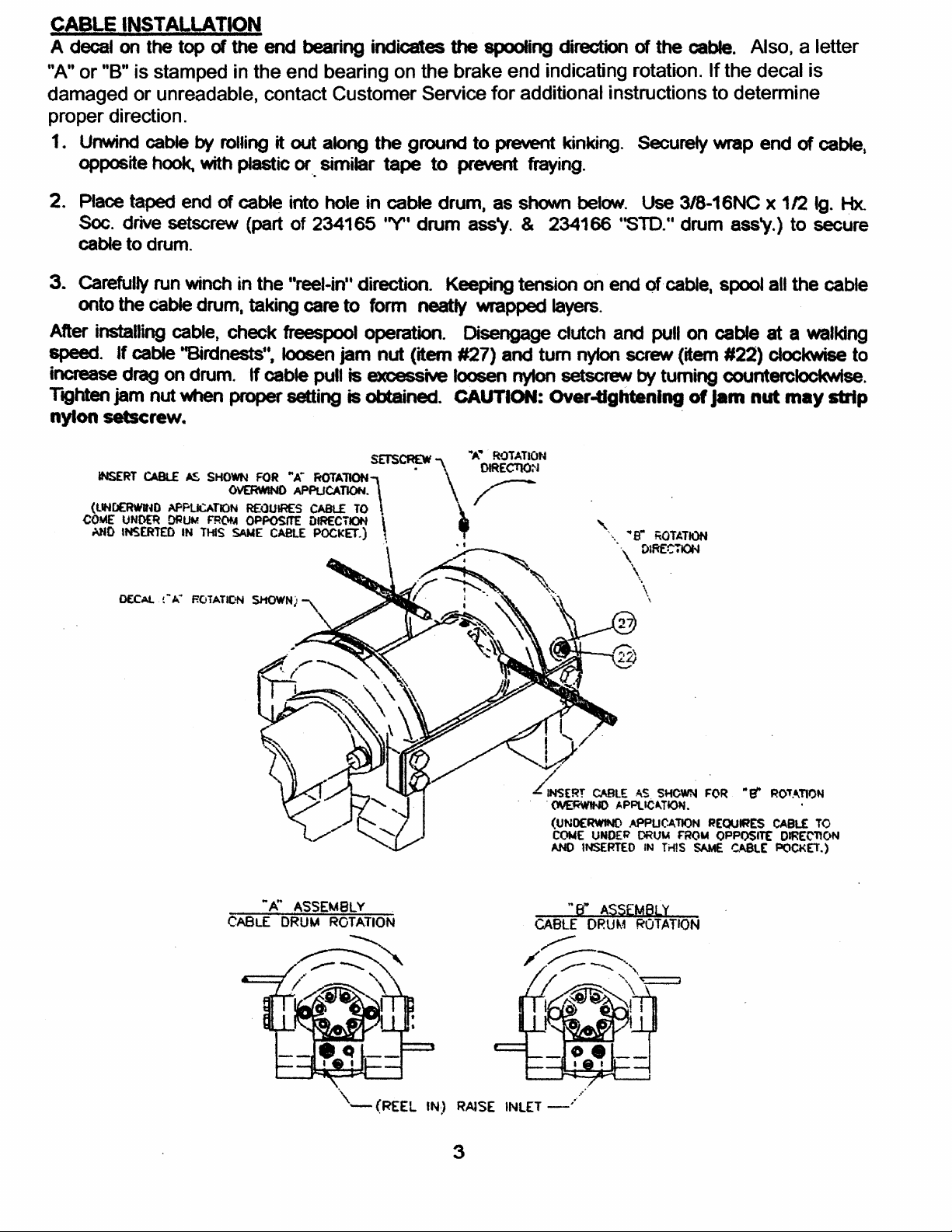
Page 3
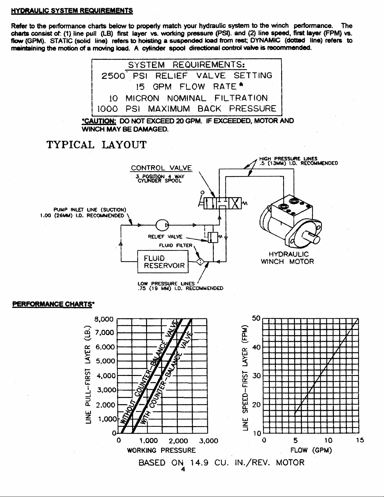
Page 4
Page 5
Page 6
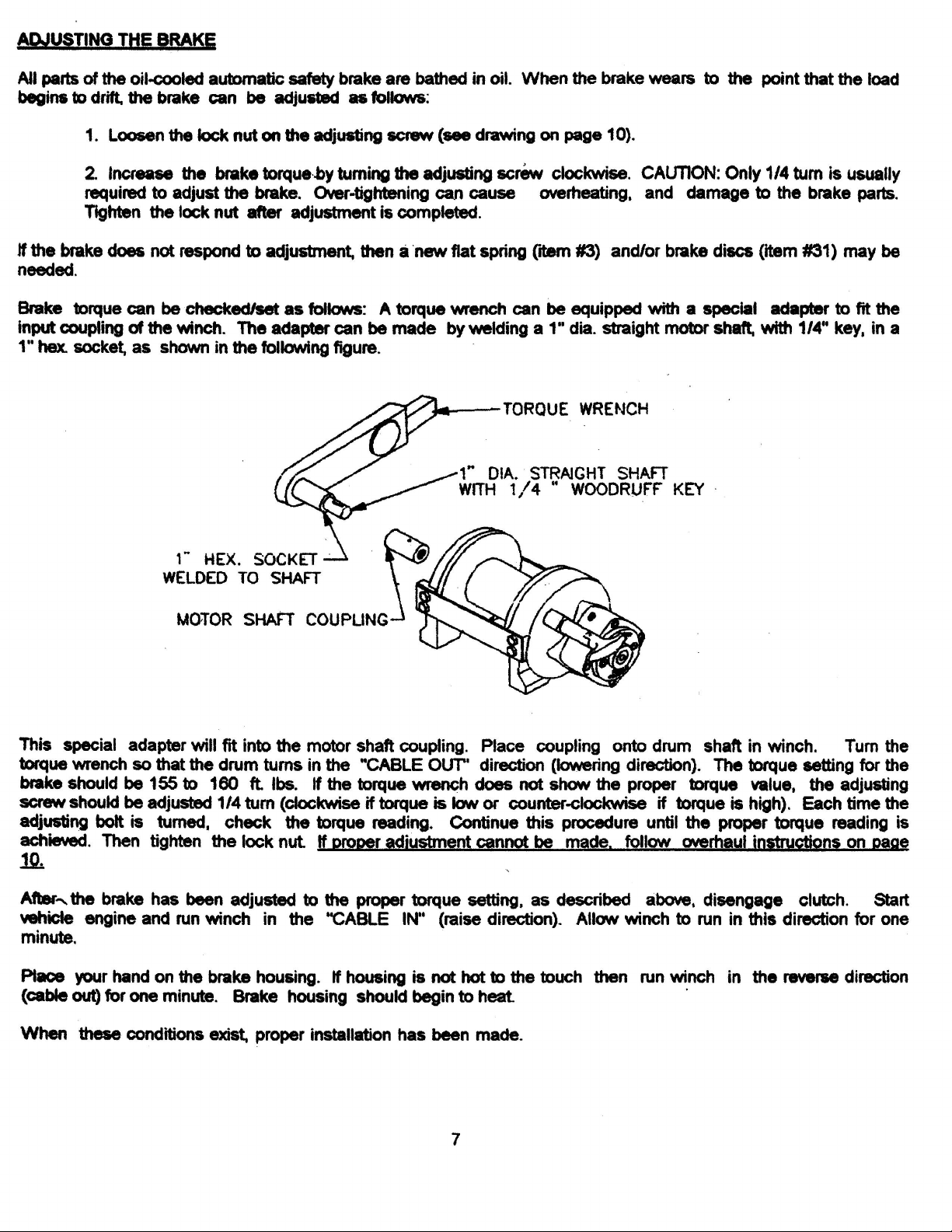
Page 7

OPERATION
The best way to get acquainted with how your winch operates is to make test runs before you actually use it.
Plan your test in advance. Remember, you hear your winch, as well as see it operate. Get to recognize the
sounds of a light steady pull, a heavy pull, and sounds caused by load jerking or shifting. Avoid conditions
where load shifts or jerks occur, as they may indicate a dangerous situation.
The uneven spooling of cable, while pulling a load, is not a problem, unless there is a cable pileup on one end of
drum. If this happens, reverse the winch to relieve the load and move your anchor point further to the center of
the vehicle. After the job is done you can unspool and rewind for a neat lay of the cable.
When pulling a heavy load place a blanket, jacket or tarpaulin over the cable about five or six feet behind the
hook. In the event of a broken cable, this will slow the snap back of the cable and could prevent serious injury.
The winch clutch allows rapid unspooling of the cable, from cable drum, for hooking onto the load. The clutch is
operated by the clutch shifter lever or air shifter.
WARNING: DO NOT DISENGAGE CLUTCH UNDER LOAD.
MANUAL CLUTCH SHIFTER
TO DISENGAGE CLUTCH: Run the winch in the reverse (reel out) direction until load is off the cable. Pull handle
out and rotate 90
TO ENGAGE CLUTCH: Pull handle out, rotate 90
handle snaps fully into the "ENGAGED" position. DO NOT attempt to pull a load unless the handle is fully at the
"ENGAGED" position. If manual shift indicator light is present, the green light is lit when clutch is fully
"ENGAGED". DO NOT attempt to pull a load unless the green light is lit. To hookup light to the vehicle electrical
system refer to the Electrical Schematic on page 15.
o
. With handle in the "DISENGAGED" position cable may now be free-spooled from drum.
(Refer to page 14)
o
and release handle. Run the winch in reverse until the clutch
AIR CYLINDER CLUTCH SHIFTER (Refer to page 15)
TO DISENGAGE CLUTCH: Run the winch in the reverse (reel out) direction until load is off the cable. Apply air
pressure to the .125-27 NPT port: 80 PSI (min.), 150 PSI (max.).
PSI.
TO ENGAGE CLUTCH: Remove air pressure form the cylinder (a return spring engages the plunger). Run winch
in reverse until the clutch engagement indicator light (green light) is lit.
green light is lit. To hookup light to the vehicle electrical system refer to the Electrical Schematic on page 15.
CAUTION:
DO NOT
Pressure must not exceed 150
attempt to pull a load unless the
MAINTENANCE
1. Inspect the cable for damage and lubricate frequently. If the cable becomes frayed with broken strands, re-
place immediately. Cable and hook assembly (100' lg. cable) P/N 524118 ("Y" drum) or (150' lg. cable) P/N
524119 ("STD" drum) may be purchased from a Ramsey distributor.
2.
Check that the clutch is fully engaging. See OPERATION instructions, above,for the appropriate clutch shifter.
FOR MANUAL CLUTCH ONLY: Monthly disengage clutch, put several drops of oil on the shaft and work
clutch IN and OUT several times to lubricate inside of clutch cylinder
3. Check brake for drift. Refer to page 7.
4.
Check oil level of winch brake housing every month. Remove oil level plug (refer to pg.13). Oil level should
be kept up to oil level hole (plus or minus 1/8"). Replace oil annually or more often if winch is used frequently.
Use 1/2 pint of Mobilfluid 424, Phillips HG Fluid, Texaco TDH, Shell Oil Co. Donax TD high performance tractor transmission fluid or equivalent, and for quietest operation, add 1/4 fl. oz. of an oil additive (available from
the factory).
5. Check to see that drum cable does not overrun (BIRDNEST) when freespooling. Refer to page 3.
Replace drum bushings and seals when seals begin to seep grease. Refer to OVERHAUL INSTRUCTIONS,
6.
page 8. Add additional lubricant, Mobilith SHC 007, to gears if required.
5
Page 8

TROUBLE SHOOTING GUIDE
CONDITIONS POSSIBLE CAUSE CORRECTION _____
DRUM WILL NOT ROTATE Winch not mounted squarely, Check mounting. Refer to
AT NO LOAD causing end bearings to bind up drum. WINCH MOUNTING page 2.
Brake damaged. Inspect and replace brake.
Gears damaged. Inspect and replace damaged gears.
------------------------------------------------------------------------------------------------------------------------------------------------------------------DRUM WILL NOT ROTATE Load greater than rated Refer to Specifications pg.1
UNDER LOAD capacity of winch. for line pull rating.
Low hydraulic system Check pressure. Refer to HYDRAULIC
pressure. SYSTEMS performance charts pg. 4.
Winch not mounted squarely, Check mounting. Refer to
causing end bearing to bind WINCH MOUNTING pg. 2.
up drum.
------------------------------------------------------------------------------------------------------------------------------------------------------------------WINCH RUNS TOO SLOW Low hydraulic system flow rate. Check flow rate. Refer to
HYDRAULIC SYSTEMS flow chart page 4.
Motor worn out. Replace motor.
------------------------------------------------------------------------------------------------------------------------------------------------------------------DRUM WILL NOT Clutch not disengaged. Check OPERATION. Refer to page 5.
FREESPOOL Check ADJUSTMENT. Refer to page 12.
Winch not mounted squarely, Check mounting. Refer to WINCH
causing end bearings to bind drum. MOUNTING pg. 2
Side-mount bolts (item #18, Check bolt length. Bolt thread MUST NOT
Page 17) too long causing engage threaded holes in sides of end
binding of ring gear. bearing by more than the .50 inch thread
depth in the end bearing. Refer to page 15.
------------------------------------------------------------------------------------------------------------------------------------------------------------------OIL LEAKAGE Damaged brake housing Replace gasket. Check for plugged
gasket or breather. breather. Refer to pgs. 8 & 10.
Damaged brake hub seal. Replace seal. Refer to pg. 10.
------------------------------------------------------------------------------------------------------------------------------------------------------------------OIL LEAKAGE FROM Breather below oil level. Check oil level.
BREATHER PLUG
------------------------------------------------------------------------------------------------------------------------------------------------------------------LOADS DRIFT Brake needs adjusting. Adjust brake. Refer to pg. 7.
------------------------------------------------------------------------------------------------------------------------------------------------------------------CABLE BIRDNESTS WHEN Drag screw improperly Adjust nylon drag screw.
CLUTCH IS DISENGAGED adjusted. Refer to pg. 3.
------------------------------------------------------------------------------------------------------------------------------------------------------------------EXCESSIVE NOISE Brake torque too high. Reduce torque. Refer to page 7.
Hydraulic system flow too high Check flow rate. Refer to HYDRAULIC
SYSTEMS flow chart pg. 4.
Brake oil level low. Check oil level, add oil if necessary.
Drum in bind, winch not Check mounting. Refer to
mounted squarely. WINCH MOUNTING pg. 2
------------------------------------------------------------------------------------------------------------------------------------------------------------------DRUM CHATTERS, Low hydraulic system flow. Check flow rate. Refer to HYDRAULIC
in "REEL IN" direction SYSTEMS flow chart pg. 4.
Low hydraulic system Check relief valve setting. Refer to
relief pressure setting. HYDRAULIC SYSTEMS pg. 4.
6
Page 9
Page 10

INSTRUCTIONS FOR OVERHAUL OF RAMSEY WINCH
MODEL RPH 8,000
Remove breather plug and reducer (item #34 and #39) from winch. Drain oil from winch by
removing plug (item #40). Remove motor (item #35), coupling (item #31) from winch by
unscrewing capscrews (item #24). If coupling is being replaced, be sure pin (item #41) is
installed. Tap motor lightly to disengage. Replace all o-rings and seals with new one during re-
assembly (order kit #246042). If necessary, remove valve (item #49) from motor by removing
lockwashers (item #52) and capscrews (item #21).
8
Page 11

Page 12

Page 13

Page 14

Page 15

Before installing motor, check brake adjustment (refer to page 7, ADJUSTING THE
BRAKE).
Place splined end of coupling (item #31), with spirol pin (item #41) installed, inside of
motor end bearing housing (item #7) and slide over splines on end of input shaft. Place
o-ring (item #38) around motor pilot. Mount motor (item #35) to end bearing by aligning
key on motor shaft with keyway in coupling. Be sure that motor mounts flush to end
bearing and that o-ring is set securely in place between motor and end bearing. Secure
motor to end bearing using two capscrews and lockwashers (items #24 & #30). Tighten
capscrews to 49 Ft.Lbs. (66 Nm). Thread plug (item #40) into bottom of brake housing.
Permatex can be added to threads of plug to help in sealing.
Pour a mixture of 1/2 pint (8 oz.) of Mobilfluid 424, Phillips HG Fluid, Texaco TDH, Shell
Oil Co. Donax TD high performance tractor transmission fluid, or equivalent, and 1/4 oz.
of an oil additive (available from the factory) into oil level hole. Oil level should be kept
at oil level hole (plus or minus 1/8"). Thread plug (item #40) into oil level hole. Insert
reducer (item #39) into hole in top of brake housing and breather plug (item #34) into
reducer. Tighten plugs and reducer securely.
13
Page 16

Page 17

Page 18

PARTS LIST RPH-8,000 WITH MANUAL CLUTCH SHIFTER
ITEM QTY. PART NO. DESCRIPTION
1 1 234165 DRUM ASS'Y. "Y"
1 234166 DRUM ASS'Y. "STD."
2 1 276048 SHIFTER ASS'Y.
3 1 306035 SPRING-FLAT, BRK.
*4 1 314017 CAM PLATE-”A” ROTATION
1 314018 CAM PLATE-”B” ROTATION
5 1 334174 GEAR-OUTPUT, SUN
6 1 444084 GEAR-RING
**7 1 338326 END BEARING-MOTOR
**8 1 338327 HOUSING-GEAR, END BEARING
**9 1 338328 HOUSING-BRAKE
*10 1 314019 HUB PLATE
11 1 352021 RETAINER PLATE
12 1 357489 SHAFT-INPUT "Y"
1 357490 SHAFT-INPUT "STD."
13 2 395163 TIE PLATE "Y"
2 395172 TIE PLATE "STD."
*14 3 400007 BALL
15 1 412084 BUSHING-DRUM, MOTOR END
16 1 412085 BUSHING-DRUM, GEAR
17 2 414273 BOLT-3/8-16NC X 1-3/4, HX, GR. 5
18 8 414581 CAPSCREW-1/2-13NC X 3/4 LG. HX. HD., GR. 5, Z/P
19 1 414622 BOLT-1/2-13NC X 2-1/4, HX. HD., GR. 5, ALL-THD.
20 2 414836 CAPSCREW-1/4-20NC X 1/2, HX. SOC. HD.
21 4 414159 CAPSCREW-5/16-18NC X 2-1/2, HX. HD. GR5 Z/P
22 1 414926 SETSCREW-3/8-16NC X 1, SOCKET, NYLON
23 4 414934 CAPSCREW-3/8-16NC X 2-3/4, HX. SOC. HD.
24 2 414952 CAPSCREW-1/2-13NC X 1-1/2, SOC. HD.
25 1 416016 SETSCREW-1/4-20NC X 1/4 HX. SOC. HD.
**26 2 418034 NUT 3/8-16NC HEX.REG.
27 1 418036 NUT 3/8-16NC HEX. JAM
28 1 418061 NUT-1/2-13NC HEX. JAM
29 4 418184 WASHER-3/8 ID X 5/8 OD X 1/16 FLAT ALUM
30 2 418218 LOCKWASHER-1/2 ID MED. SECT.
31 1 431014 COUPLING-HYD. MOTOR
32 2 438018 PLATE-BRAKE
33 1 442212 GASKET-BRK. HSG.
34 1 456008 RELIEF FITTING
35 1 458074 MOTOR-HYD. (FOR MODEL WITH COUNTERBALANCE VALVE)
1 458075 MOTOR-HYD. (FOR MODEL WITHOUT COUNTERBALANCE VALVE)
36 1 462046 O-RING
37 2 462047 QUAD-RING
38 1 462048 O-RING
39 1 468002 REDUCER
40 2 468018 PIPE PLUG
41 1 470033 SPIROL PIN
*42 1 472051 PLUG
43 1 472052 PLUG
44 1 486076 SEAL
45 1 486080 SEAL-GEAR HSG.
46 1 518037 SHIM
47 2 490003 SNAP RING
48 1 494010 SPRING
49 1 516008 VALVE-COUNTERBALANCE ("A" ROTATION)
1 516009 VALVE-COUNTERBALANCE ("B" ROTATION)
50 1 518047 WASHER-THRUST
*51 1 340077 BRAKE SHAFT
52 4 418163 LOCKWASHER - 5/16 MED SECT Z/P
16
* EFFECTIVE SERIAL NUMBER: 2038147
** EFFECTIVE DATE CODE: H07702041
Page 19

17
Page 20

PARTS LIST RPH-8,000 WITH MANUAL CLUTCH SHIFTER
AND CLUTCH ENGAGEMENT INDICATOR LIGHT
ITEM
QTY. PART NO. DESCRIPTION
1 1 234165 DRUM ASS'Y. "Y"
1 234166 DRUM ASS'Y. "STD."
2 1 236020 LIGHT ASS'Y.
3 1 276048 SHIFTER ASS'Y.
4 1 306035 SPRING-FLAT, BRK.
*5 1 314017 CAM PLATE-”A” ROTATION
1 314018 CAM PLATE-”B” ROTATION
6 1 334174 GEAR-OUTPUT, SUN
7 1 444084 GEAR-RING
**8 1 338326 END BEARING-MOTOR
**9 1 338327 HOUSING-GEAR, END BEARING
**10 1 338328 HOUSING-BRAKE
11 1 314019 HUB PLATE
12 1 350598 PLATE-LIGHT MTG.
13 1 352021 RETAINER PLATE
14 1 357489 SHAFT-INPUT "Y"
1 357490 SHAFT-INPUT "STD."
15 2 395163 TIE PLATE "Y"
2 395172 TIE PLATE "STD."
*16 3 400007 BALL
17 1 412084 BUSHING-DRUM, MOTOR END
18 1 412085 BUSHING-DRUM, GEAR
19 2 414273 BOLT-3/8-16NC X 1-3/4, HX, GR. 5
20 8 414581 CAPSCREW-1/2-13NC X 3/4 LG. HX. HD., GR. 5, Z/P
21 1 414622 BOLT-1/2-13NC X 2-1/4, HX. HD., GR. 5, ALL-THD.
22 2 414836 CAPSCREW-1/4-20NC X 1/2, HX. SOC. HD.
23 4 414159 CAPSCREW-5/16-18NC X 2-1/2, HX. HD. GR5 Z/P
24 1 414926 SETSCREW-3/8-16NC X 1, SOCKET, NYLON
25 4 414934 CAPSCREW-3/8-16NC X 2-3/4, HX. SOC. HD.
26 2 414952 CAPSCREW-1/2-13NC X 1-1/2, SOC. HD.
27 1 416016 SETSCREW-1/4-20NC X 1/4 HX. SOC. HD.
**28 2 418034 NUT 3/8-16NC HEX.REG.
29 1 418036 NUT 3/8-16NC HEX. JAM
30 1 418061 NUT-1/2-13NC HEX. JAM
31 4 418184 WASHER-3/8 ID X 5/8 OD X 1/16 FLAT ALUM
32 2 418218 LOCKWASHER-1/2 ID MED. SECT.
33 1 431014 COUPLING-HYD. MOTOR
34 2 438018 PLATE-BRAKE
35 1 442212 GASKET-BRK. HSG.
36 1 456008 RELIEF FITTING
37 1 458074 MOTOR-HYD. (FOR MODEL WITH COUNTERBALANCE VALVE)
1 458075 MOTOR-HYD. (FOR MODEL WITHOUT COUNTERBALANCE VALVE)
38 1 462046 O-RING
39 2 462047 QUAD-RING
40 1 462048 O-RING
41 1 468002 REDUCER
42 2 468018 PIPE PLUG
43 1 470033 SPIROL PIN
*44 1 472051 PLUG
45 1 482013 GROMMET
46 1 482045 RUBBER BOOT
47 1 486076 SEAL
48 1 486080 SEAL-GEAR HSG.
49 2 490003 SNAP RING
50 1 494010 SPRING
51 1 504021 SWITCH ASS'Y.
52 1 516008 VALVE-COUNTERBALANCE ("A" ROTATION)
1 516009 VALVE-COUNTERBALANCE ("B" ROTATION)
53 1 518047 WASHER-THRUST
*54 1 340077 SHAFT - BRAKE
55 4 418163 LOCKWASHER - 5/16 MED SECT Z/P
18
* EFFECTIVE SERIAL NUMBER: 2038147
** EFFECTIVE DATE CODE: H07702041
Page 21

19
Page 22

PARTS LIST RPH-8,000 WITH AIR-CYLINDER CLUTCH SHIFTER
ITEM QTY. PART NO. DESCRIPTION
1 1 234165 DRUM ASS'Y. "Y"
1 234166 DRUM ASS'Y. "STD."
2 1 236020 LIGHT ASS'Y.
3 1 276058 SHIFTER ASS'Y.-AIR
4 1 306035 SPRING-FLAT, BRK.
*5 1 314017 CAM PLATE-”A” ROTATION
1 314018 CAM PLATE-”B” ROTATION
6 1 334174 GEAR-OUTPUT, SUN
7 1 444084 GEAR-RING
**8 1 338326 END BEARING-MOTOR
**9 1 338327 HOUSING-GEAR, END BEARING
**10 1 338328 HOUSING-BRAKE
*11 1 314019 HUB-PLATE
12 1 350598 PLATE-LIGHT MTG.
13 1 352021 RETAINER PLATE
14 1 357489 SHAFT-INPUT "Y"
1 357490 SHAFT-INPUT "STD."
15 2 395163 TIE PLATE "Y"
2 395172 TIE PLATE "STD."
*16 3 400007 BALL
17 1 412084 BUSHING-DRUM, MOTOR END
18 1 412085 BUSHING-DRUM, GEAR
19 2 414273 BOLT-3/8-16NC X 1-3/4, HX, GR. 5
20 8 414581 CAPSCREW-1/2-13NC X 3/4 LG. HX. HD., GR. 5, Z/P
21 1 414622 BOLT-1/2-13NC X 2-1/4, HX. HD., GR. 5, ALL-THD.
22 2 414836 CAPSCREW-1/4-20NC X 1/2, HX. SOC. HD.
23 4 414159 CAPSCREW-5/16-18NC X 2-1/2, HX. HD., GR5 Z/P
24 1 414926 SETSCREW-3/8-16NC X 1, SOCKET, NYLON
25 4 414934 CAPSCREW-3/8-16NC X 2-3/4, HX. SOC. HD.
26 2 414952 CAPSCREW-1/2-13NC X 1-1/2, SOC. HD.
27 1 416016 SETSCREW-1/4-20NC X 1/4 HX. SOC. HD.
**28 2 418034 NUT 3/8-16NC HEX.REG.
29 1 418036 NUT 3/8-16NC HEX. JAM
30 1 418061 NUT-1/2-13NC HEX. JAM
31 4 418184 WASHER-3/8 ID X 5/8 OD X 1/16 FLAT ALUM
32 2 418218 LOCKWASHER-1/2 ID MED. SECT.
33 1 431014 COUPLING-HYD. MOTOR
34 2 438018 PLATE-BRAKE
35 1 442212 GASKET-BRK. HSG.
36 1 456008 RELIEF FITTING
37 1 458074 MOTOR-HYD. (FOR MODEL WITH COUNTERBALANCE VALVE)
1 458075 MOTOR-HYD. (FOR MODEL WITHOUT COUNTERBALANCE VALVE)
38 1 462046 O-RING
39 2 462047 QUAD-RING
40 1 462048 O-RING
41 1 468002 REDUCER
42 2 468018 PIPE PLUG
43 1 470033 SPIROL PIN
*44 1 472051 PLUG
45 1 482013 GROMMET
46 1 482045 RUBBER BOOT
47 1 486076 SEAL
48 1 486080 SEAL-GEAR HSG.
49 2 488007 SHIM
50 2 490003 SNAP RING
51 1 494010 SPRING
52 1 504021 SWITCH ASS'Y.
53 1 516008 VALVE-COUNTERBALANCE ("A" ROTATION)
1 516009 VALVE-COUNTERBALANCE ("B" ROTATION)
54 1 518047 WASHER-THRUST
55 1 340077 SHAFT - BRAKE
*56 4 418163 LOCKWASHER 5/16 MED SECT Z/P
* EFFECTIVE SERIAL NUMBER: 2038147
** EFFECTIVE DATE CODE: H07702041
20
Page 23

21
Page 24

PARTS LIST RPH-8,000 WITH BLOCKED CLUTCH
ITEM QTY. PART NO. DESCRIPTION
1 1 234166 DRUM ASS'Y. "STD."
2 1 299693 PLUNGER ASSY.
3 1 306035 SPRING-FLAT, BRK.
*4 1 314017 CAM PLATE-”A” ROTATION
1 314018 CAM PLATE-”B” ROTATION
5 1 334174 GEAR-OUTPUT, SUN
6 1 444084 GEAR-RING
**7 1 338326 END BEARING-MOTOR
**8 1 338327 HOUSING-GEAR, END BEARING
**9 1 338328 HOUSING-BRAKE
*10 1 314019 HUB-PLATE
11 1 352021 RETAINER PLATE
12 1 357490 SHAFT-INPUT
13 2 395172 TIE PLATE
*14 3 400007 BALL
15 1 412084 BUSHING-DRUM, MOTOR END
16 1 412085 BUSHING-DRUM, GEAR
17 2 414273 BOLT-3/8-16NC X 1-3/4, HX, GR. 5
18 8 414581 CAPSCREW-1/2-13NC X 3/4 LG. HX. HD., GR. 5, Z/P
19 1 414622 BOLT-1/2-13NC X 2-1/4, HX. HD., GR. 5, ALL-THD.
20 2 414836 CAPSCREW-1/4-20NC X 1/2, HX. SOC. HD.
21 4 414159 CAPSCREW-5/16-18NC X 2-1/2, HX. HD., GR5 Z/P
22 1 414926 SETSCREW-3/8-16NC X 1, SOCKET, NYLON
23 4 414934 CAPSCREW-3/8-16NC X 2-3/4, HX. SOC. HD.
24 2 414952 CAPSCREW-1/2-13NC X 1-1/2, SOC. HD.
25 1 416016 SETSCREW-1/4-20NC X 1/4 HX. SOC. HD.
**26 2 418034 NUT 3/8-16NC HEX.REG.
27 1 418036 NUT 3/8-16NC HEX. JAM
28 1 418061 NUT-1/2-13NC HEX. JAM
29 1 418088 NUT-JAM 5/8-18NF HX Z/P
30 4 418184 WASHER-3/8 ID X 5/8 OD X 1/16 FLAT ALUM
31 2 418218 LOCKWASHER-1/2 ID MED. SECT.
32 1 431014 COUPLING-HYD. MOTOR
33 2 438018 PLATE-BRAKE
34 1 442212 GASKET-BRK. HSG.
35 1 456008 RELIEF FITTING
36 1 458075 MOTOR-HYD. (FOR MODEL WITH COUNTERBALANCE VALVE)
37 1 462046 O-RING
38 2 462047 QUAD-RING
39 1 462048 O-RING
40 1 468002 REDUCER
41 2 468018 PIPE PLUG
42 1 470033 SPIROL PIN
*43 1 472051 PLUG
44 1 472052 PLUG
45 1 486076 SEAL
46 1 486080 SEAL-GEAR HSG.
47 1 518037 SHIM
48 2 490003 SNAP RING
49 1 494010 SPRING
50 1 518047 WASHER-THRUST
*51 1 340077 SHAFT - BRAKE
* EFFECTIVE SERIAL NUMBER: 2038147
** EFFECTIVE DATE CODE: H07702041
22
Page 25

23
Page 26

NOTES
Page 27

NOTES
Page 28

LIMITED WARRANTY
RAMSEY WINCH warrants each new RAMSEY WINCH to be free from defects in
material and workmanship for a period of one (1) year from date of purchase.
The obligation under this warranty, statutory or otherwise, is limited to the replacement or repair at the Manufacturer’s factory, or at a point designated by the
Manufacturer, of such part that shall appear to the Manufacturer, upon inspection of
such part, to have been defective in material or workmanship. This warranty does
not obligate RAMSEY WINCH to bear the cost of labor or transportation charges in
connection with the replacement or repair of defective parts, nor shall it apply to a
product upon which repair or alterations have been made, unless authorized by
Manufacturer, or for equipment misused, neglected, or which has not been install
correctly.
RAMSEY WINCH shall in no event be liable for special or consequential damages.
RAMSEY WINCH makes no warranty in respect to accessories such as being subject to the warranties of their respective manufacturers. RAMSEY WINCH, whose
policy is one of continuous improvement, reserves the right to improve its products
through changes in design or materials as it may deem desirable without being obligated to incorporate such changes in products of prior manufacture.
If field service at the request of the Buyer is rendered and the fault is found not to
be with RAMSEY WINCH’s product, the Buyer shall pay the time and expense to the
field representative. Bills for service, labor, or other expenses that have been
incurred by the Buyer without the approval or authorization by RAMSEY WINCH will
not be accepted.
See warranty card for details.
OM-912449-0305-S
RAMSEY WINCH COMPANY
P.O. BOX 581510
TULSA, OKLAHOMA 74158-1510
TELEPHONE: (918) 438-2760
FAX: (918) 438-6688
http://www.ramsey.com
 Loading...