

Page 1
OPERATING, SERVICE,
AND MAINTENANCE
MANUAL
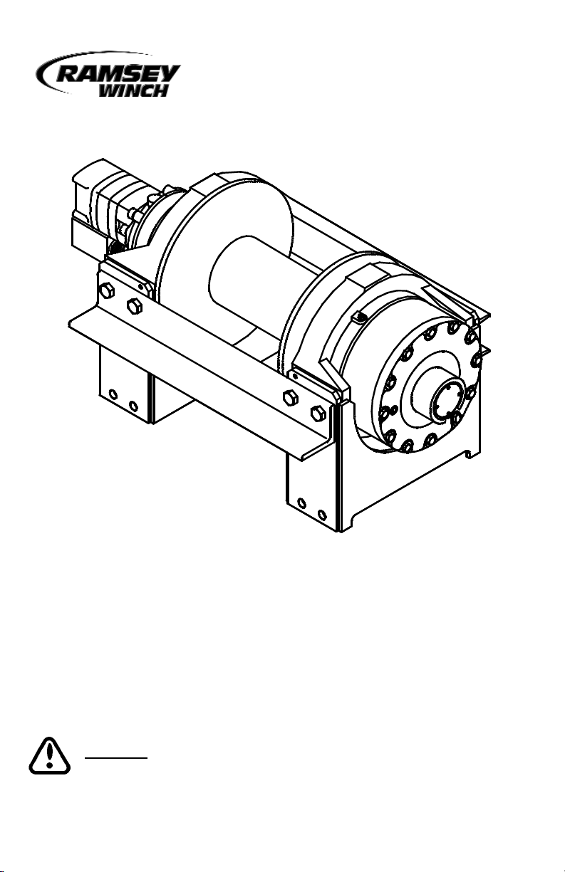
MODEL RPH-35,000
INDUSTRIAL PLANETARY WINCH
CAUTION: READ AND UNDERSTAND THIS MANUAL BEFORE
INSTALLATION AND OPERATION OF WINCH. SEE WARNINGS!
Page 2

TABLE OF CONTENTS
INTRODUCTION . . . . . . . . . . . . . . . . . . . . . . . . . . . . . . . . . . . . . . . . . . . . . . . .1
WARRANTY INFORMATION . . . . . . . . . . . . . . . . . . . . . . . . . . . . . . . . . . . . . . .1
SPECIFICATIONS . . . . . . . . . . . . . . . . . . . . . . . . . . . . . . . . . . . . . . . . . . . . . . .1
WARNINGS . . . . . . . . . . . . . . . . . . . . . . . . . . . . . . . . . . . . . . . . . . . . . . . . . . .1
WINCH FRAME MOUNTING . . . . . . . . . . . . . . . . . . . . . . . . . . . . . . . . . . . . . . .2
CABLE INSTALLATION . . . . . . . . . . . . . . . . . . . . . . . . . . . . . . . . . . . . . . . . . . .2
HYDRAULIC SYSTEM REQUIREMENTS . . . . . . . . . . . . . . . . . . . . . . . . . . . . . .2
PERFORMANCE CHARTS . . . . . . . . . . . . . . . . . . . . . . . . . . . . . . . . . . . . . . . .2
TYPICAL LAYOUT . . . . . . . . . . . . . . . . . . . . . . . . . . . . . . . . . . . . . . . . . . . . . .3
CLUTCH OPERATION . . . . . . . . . . . . . . . . . . . . . . . . . . . . . . . . . . . . . . . . . . . .3
WINCH OPERATION . . . . . . . . . . . . . . . . . . . . . . . . . . . . . . . . . . . . . . . . . . . . .3
MAINTENANCE . . . . . . . . . . . . . . . . . . . . . . . . . . . . . . . . . . . . . . . . . . . . . . . .4
TROUBLESHOOTING . . . . . . . . . . . . . . . . . . . . . . . . . . . . . . . . . . . . . . . . . . . .4
INSTRUCTIONS FOR OVERHAUL . . . . . . . . . . . . . . . . . . . . . . . . . . . . . . . .5-12
MOUNTING CONFIGURATIONS . . . . . . . . . . . . . . . . . . . . . . . . . . . . . . . . . . . .12
DIMENSIONAL DRAWING . . . . . . . . . . . . . . . . . . . . . . . . . . . . . . . . . . . . . . .13
PARTS LIST AND PART DRAWING . . . . . . . . . . . . . . . . . . . . . . . . . . . . . .14-15
LIMITED WARRANTY . . . . . . . . . . . . . . . . . . . . . . . . . . . . . . . . . .BACK COVER
Page 3

RAMSEY HYDRAULIC PLANETARY WINCH MODEL RPH 35,000
PLEASE READ THIS MANU
AL CAREFULLY
This manual contains useful ideas in obtaining the most efficient operation from your Ramsey
Winch, and safety procedures one needs to know before operating a Ramsey Winch. Do not
operate this winch until you have carefully read and understand the "WARNINGS" and
"OPERATION" sections of this manual.
W
ARRANTY INFORMATION
Ramsey Winches are designed and built to exacting specifications. Great care and skill go
into every winch we make. If the need should arise, warranty procedure is outlined on the
back of your self-addressed postage paid warranty card. Please read and fill out the enclosed
warranty card and send it to Ramsey Winch Company. If you have any problems with our
winch, please follow instructions for prompt service on all warranty claims. Refer to back
page for limited warranty.
SPECIFICA
TIONS*
NOTE: The rated line pulls shown are for the winch only. Consult the wire rope manufacturer
for wire rope ratings.
W
ARNINGS:
CLUTCH MUST BE TOTALLY ENGAGED BEFORE STARTING THE WINCHING OPERATION.
DO NOT START WINCH MOTOR BEFORE ENGAGING CLUTCH
DO NOT DISENGAGE CLUTCH UNDER LOAD.
STAY OUT FROM UNDER AND AWAY FROM RAISED LOADS.
STAND CLEAR OF CABLE WHILE PULLING. DO NOT TRY TO GUIDE CABLE.
DO NOT EXCEED MAXIMUM LINE PULL RATINGS SHOWN IN TABLE.
DO NOT USE WINCH TO LIFT, SUPPORT, OR OTHERWISE TRANSPORT PEOPLE.
A MINIMUM OF 5 WRAPS OF CABLE AROUND THE DRUM BARREL IS NECESSARY TO
HOLD THE LOAD.
CABLE ANCHOR IS NOT DESIGNED TO HOLD LOAD.
1
Rated Line Pull (lbs. )
……………………………………………………
35,000
(Kg.)
……………………………………………………
15,909
Gear Reducti on
……………………………………………………………
31.89:1
Weight (without cable) …………………………………………. 504 lbs . (229 Kg)
12345
lbs. 35,000 28,600 24,200 21,000 18,500
Kg. 15,909 13,000 11000 9,545 8,390
ft. 25 60 105 155 200
m 7.6 18.3 32 47. 2 60
FPM 15. 4 18.6 21.1 23.5 28
MPM 4.7 5.7 6. 4 7. 2 8.5
* These spec ifications are based on recommended wire rope of .75 i nch dia.
extra improved plow steel or equivalent
LAYER OF CABLE
*Rated line pull
per layer
*Cable Capacity
*Line Speed (at
15 GPM)
Page 4

WINCH FRAME MOUNTING
Use (8) 5/8 inch diameter grade 5 or better bolts to attach mounting frame to wrecker.
CABLE INST
ALLATION
1. Unwind cable by rolling it out along the ground to prevent kinking. Securely wrap end of
wire rope, opposite hook, with plastic or similar tape to prevent fraying.
2. Inser t the end of the cable opposite the hook end into the hole in the drum barrel. Secure
cable to drum barrel using setscrew furnished with winch. TIGHTEN SETSCREW
SECURELY.
3. Carefully run winch in the "reel-in" direction. Keeping tension on end of cable, spool all
the cable onto the cable drum, taking care to form neatly wrapped layers.
The wire rope can easily be removed from the drum by loosening the setscrew.
HYDRA
ULIC SYSTEM REQUIREMENTS
Refer to the performance char ts, below, to properly match your hydraulic system to RPH
35000 winch performance. The charts consist of :
(1) Line pull (lb.) first layer vs. working pressure (PSI) and (2) Line speed, first layer (FPM)
vs. Flow (GPM). Performance based on a motor displacement of 11.9 cubic inches with 15
GPM maximum flow rate. See page 13 for motor port size.
PERFORMANCE CHARTS
5000
10000
15000
20000
25000
30000
35000
0 500 1000 1500 2000 2500 3000
Pressure (PSI)
Line Pull (Lbs.)
0
10
20
30
0 5 10 15
Flow (GPM)
Line Speed (Ft/Min)
2
Page 5
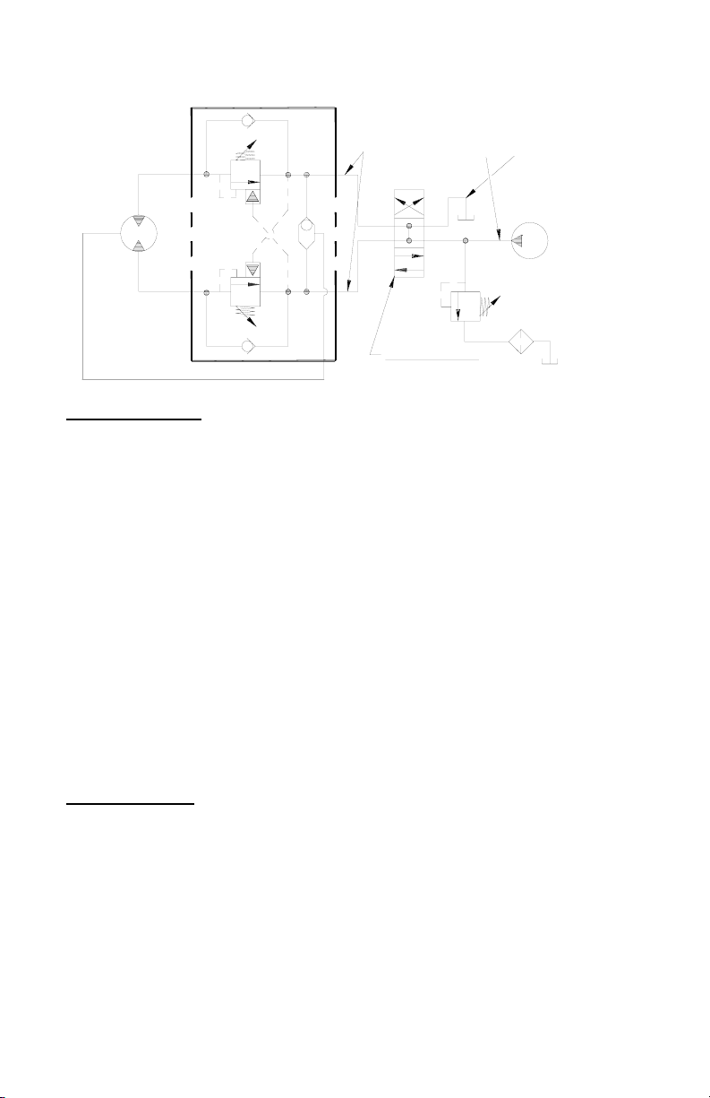
CONTROL VALVE
3 POSITION
4 WAY VALVE
(MOTOR SPOOL)
HIGH PRESSURE LINE
DUAL-A & B PORT CONTROL
WITH BRAKE RELEASE SHUTTLE
BRAKE
PORT
B
MOTOR
A
TYPICAL LAYOUT
LOW PRESSURE LINE
PUMP
CLUTCH OPERATION
To engage clutch:
1. Move the clutch control valve to the "clutch-engaged" position.
2. Anytime the temperature is below freezing, run motor in the "cable out" direction only
until the drum starts to turn. In extreme cold temperatures (below 0° F/-18° C), pull out
on the cable by hand only until the drum starts to turn.
3. Wait at least 3 seconds for the clutch to fully engage, after which the winch is ready to
winch in the cable.
WARNING: Do not attempt to engage the clutch by first running the
winch motor and then moving the clutch control valve to the "clutchengaged" position while the motor is running. Do not start picking up
the load at the same time the clutch is being engaged.
To disengage clutch:
1. Run the winch in the "cable out" direction until the load is off the cable.
2. Move the clutch control valve to the "clutch-disengaged" position.
3. The cable may now be pulled off by hand
WINCH OPERA
TION
The best way to get acquainted with how your winch operates is to make test runs before
you actually use it. Plan your test in advance. Remember, you hear your winch as well as
see it operate. Get to recognize the sounds of a light steady pull, a heavy pull, and sounds
caused by load jerking or shifting. Gain confidence in operating your winch and its use will
become second nature with you.
The uneven spooling of cable, while pulling a load, is not a problem, unless there is a cable
pileup on one end of drum. If this happens reverse the winch to relieve the load and move
your anchor point further to the center of the vehicle. After the job is done you can unspool
and rewind for a neat lay of the cable.
3
Page 6

MAINTENANCE
Adhering to the following maintenance schedule will keep your winch in top condition and
performing as it should with a minimum of repair.
A. WEEKLY
1. Check the oil level and maintain it to the oil level plug. If oil is leaking out, determine
location and repair.
2. Check the pressure relief plug in top of the gear housing. Be sure that it is not plugged.
3. Lubricate cable with light oil.
B. MONTHLY
1. Check the winch mounting bolts. If any are missing, replace them and securely tighten
any that are loose. Use grade 5 or better bolts.
2. Inspect the cable. If the cable has become frayed with broken strands, replace immedi-
ately.
C. ANNUALLY
1. Drain the oil from the winch annually or more often if winch is used frequently.
2. Fill the winch to the oil level plug with clean kerosene. Run the winch a few seconds
with no load in the reel in direction. Drain the kerosene from the winch.
3. Refill the winch to the oil level plug with all purpose SAE 80W-140 gear oil.
4. Inspect frame and surrounding structure for cracks or deformation.
CONDITION POSSIBLE CAUSE CORRECTION
Seal s damaged or worn Repl ace seal.
Too much oil Drain excess oil. R efer to Operation.
Damaged gasket Repl ace gasket.
Low flow rate
Check flow rate. Refer to Specifications
page 1.
Hydraulic motor worn out Replace motor.
CABLE DRUM WILL NOT
FREESPOOL
Clutch not disengaged
Check air pressure to clutch cylinder 90
PSI minimum required. Refer to drawing
page 13 for more information.
BRAKE WILL NOT
RELEASE
Air in hydraulic system Bleed air from brake.
OIL LEAKS FROM WINCH
WINCH RUNS TOO SLOW
TROUBLESHOOTING GUIDE
4
Page 7

INSTRUCTIONS FOR OVERHAUL
1. Drain oil from gear hous-
ing (item #9) by removing plug (item #42) from
end bearing. Remove
reducer and relief fitting
(items #41 & #36).
If new air cylinder is
required, remove air cylinder (item #32) from
adapter (item #4) by
removing (4) capscrews
(item #23). Remove
washer (item #25), nut
and setscrew (items #26 & #21) and insert (item #29) from end of air cylinder rod.
Apply Loc-tite to threads of nut (item #26) and thread onto setscrew (item #21) to 3/8
inch from drive end, as shown at right. Apply Loc-tite to threads of setscrew and thread
insert (item #29) over end of setscrew and against nut. Use setscrew and nut to thread
insert (item #29) into end of air cylinder rod. Tighten nut against cylinder rod, keeping
3/8 inch distance from drive end of setscrew to nut. If breather vent (item #37) is damaged, remove and replace. Remove air cylinder adapter (item #4) and gasket (item #34)
from gear housing cover by unscrewing (4) capscrews (item #17).
2. Disconnect tube (item #45) from
elbow (item #30) on valve (item
#46) and fitting on bottom of brake
assembly (item #31). Remove motor
(item #38) and gasket (item #35) by
removing (2) capscrews (item #20).
Remove valve (item #46), if needed,
from motor by loosening (3) capscrews.
5
Page 8

3. Remove brake assembly screws (item #47) from brake (item #33a) to access (2)
mounting screws (item #19) attaching brake adapter plate (item #33d) to end bearing
(item #8). CAUTION: Brake is spring loaded by clutch spring and must be restrained
against end bearing as mounting screws are removed. Remove coupling (item #6) and
gasket (item #33e) from end bearing. Take note of mounting configuration for proper
mounting of parts during re-assembly.
4. Remove winch from upright mounting frame (item #2) by removing (8) capscrews (item
#16), (8) lockwashers (item #24) and (4) shoulder bolts (item #27). Pull motor end
bearing (item #8) from drum assembly (item #1).
9
7
47
33c
31
33a
33e
33d
33e
19
19
47
6
Page 9

5. Pull drum assembly (item #1) upward from end bearing (item #9). Remove quad-rings
(item #39 & #40) from grooves in drum bushings. Remove input shaft (item #11),
clutch spring (item #44) and washer (item #28) from end bearing (item #9). Examine
key (item #10) and input shaft for signs of wear, replace if damaged.
Examine drum assembly (item #1) for signs of wear. If splines inside of drum driver
(332162) are damaged, drum driver must be replaced. Remove drum driver by unscrewing (8) capscrews (414964). Place well oiled o-ring (462053) into drum driver groove
and attach driver to drum (332196) using (8) capscrews (414964). Torque capscrews
to 120 ft. lbs. each, in criss-cross pattern.
Press old bushings from drum and drum driver. Remove o-rings (462054 & 462052)
from grooves in drum and drum driver bushing (412088). Place well oiled o-rings
(462054 & 462052) into grooves in drum and outer diameter of drum driver bushing
(412088). Press new bushing (412087) into end of drum opposite drum driver and
press bushing (412088) into drum driver until flange of bushings are flush against drum
and driver.
7
Page 10

6. Remove output coupling (item #7) and coupling shaft (item #5) from end bearing (item
#9). Examine bearings (item #13), pressed in output coupling, for signs of wear.
Replace bearings, if necessary, by pressing old bearings from coupling and press new
bearings into each end of output coupling. Place coupling shaft into bearings.
7. Remove (12) capscrews (item #15) to pull gear housing cover from ring gear. Remove
input thrust washer, sun gear and carrier assemblies from inside of ring gear. Remove
ring gear from end bearing (item #9). Examine shifter shaft (item #12) for signs of
wear, replace if necessary. Examine bushing (item #14) for signs of wear. Replace
bushing, if necessary, by pressing old bushing from housing and pressing new bushing
into place.
8
Page 11

8. NOTE: DETERMINE MOUNTING CONFIGURATION OF WINCH (R.H. or L.H. MOUNTED)
BEFORE ATTACHING UPRIGHT FRAME TO WINCH, TO ASSURE PARTS ARE MOUNTED
TO PROPER SIDE, REFER TO WINCH MOUNTING CONFIGURATIONS, PAGE 12.
Seat well oiled quadrings (item #39 &
#40) into groove of
bushing in each end of
drum assembly (item
#1), as shown.
Carefully set drum
assembly down over
motor end bearing (item
#8). Lift gear housing
end bearing (item #9)
and set into place on
drum assembly. Attach
upright frame (item #2)
to end bearings. Install
(4) shoulder bolts (item
#27) and hand tighten.
Install (8) capscrews
with lockwashers (item #16 & #24). Tighten (4) inner-most capscrews securely, check
rotation of cable drum. Tighten (4) outer-most capscrews securely, check rotation of
cable drum. Torque capscrews, in above inner-most then outer-most pattern, to 250 ft.
lbs. each. Torque (4) shoulder bolts to 30 ft. lbs. each. Make sure cable drum assembly
rotates freely at this point.
9. Gently tap key (item #10) into keyway of input shaft (item #11). Liberally apply grease
to shoulder of input shaft. Place spring (item #44) over splined end of shaft. Use grease
to hold spring in place on shaft. Place spring and splined end of shaft through motor end
bearing (item #8) and drum until shaft extends through bushing (item #14). Place clutch
washer (item #28) over splined end of shaft and against spring.
Place end of output coupling assembly (item #7), with longest splines, through end
bearing bushing (item #14) and mesh shaft coupling spline with splined end of shaft.
Place short splined end of shifter shaft (item #12) through washer (item #28) and into
shaft coupling (item #5), meshing splines of shifter shaft with splines in shaft coupling.
9
Page 12

10. Apply RTV sealing compound to ring gear mounting surface of end bearing (item #9).
Place ring gear onto end bearing, aligning holes in ring gear with holes and gear housing
end bearing. Use (2) capscrews to temporarily secure ring gear to end bearing.
Place (2) gear carrier assemblies into
ring gear meshing carrier gears with
ring gear. Remove (2) temporary
capscrews, making sure that ring
gear and carrier assemblies are
securely against end bearing (item
#9). Apply RTV sealing compound
to cover mounting surface of ring
gear (item #3) and attach cover to
ring gear. Use (12) capscrews (item
#15) to secure gear box to gear
housing end bearing. Torque capscrews to 39 ft. lbs. each, in crisscross pattern.
11. Slide input sun gear over shifter shaft (item #12) and mesh with teeth of input carrier.
Apply grease to input thrust washer and place into slots of air cylinder adapter (item #4).
Place gasket (item #34) into position on gear box cover with sealer and attach adapter to
cover using (4) capscrews (item #17). Apply Loctite PST thread sealer to threads of
capscrews. Torque capscrews to 13 ft. lbs. each, in criss-cross pattern.
Pull rod from air cylinder as far as possible. Slide washer (item #25) over setscrew (item
#21) and against nut attached to air cylinder rod. Place setscrew into hole of shifter
shaft (item #12). Attach new air cylinder (item #32) and gasket (item #34) with sealer,
to adapter using (4) capscrews (item #23). Apply Loctite PST thread sealer to threads of
capscrews. Torque capscrews to 5 ft. lbs. each, in criss-cross pattern.
10
Page 13

12. Align keyway of coupling (item #6) with key on end of input shaft. Slide coupling over
end of shaft. Place gasket (item #33e) into position on motor mounting surface of end
bearing (item #9). Use (2) screws (item #19) to attach the adapter plate (item #33c) to
motor end bearing. Torque capscrews to 85 ft-lbs. each. Place second gasket (item
#33e) on adapter plate. Insert brake shaft with key (item #33c) into coupling. Alternately
tighten one, then the other of the capscrews (item #47) in a back and forth manner, thus
compressing spring (item #44) and pulling the brake down against the adapter plate.
Torque capscrews to 97 ft-lbs each.
NOTE: Care must be taken to assure cover and brake module are seated properly prior to
installing 1/2-13UNC assembly bolts. Damage will occur to rotor stack or shaft snap ring
if not properly seated.
13. Attach motor (item #38) with gasket (item #35) to brake (item #33). Use (4) cap-
screws (item #20) and torque to 74 ft. lbs. each. Securely connect tube (item #45) to
fitting (item #31) on underside of brake and fitting (item #30) on valve (item #46).
19
47
47
33c
31
33a
33e
33d
33e
19
9
7
11
Page 14

14. Apply Permatex to threads of plug (item #42). Thread plug into tapped hole in bottom of
gear housing end bearing (item #9). Pour approx. 2-1/2 pints of SAE 80W-140 oil into
end bearing. Check oil level by removing oil level plug noted below. Insert relief fitting
(item #36) and thread reducer (item #41) into end bearing at oil fill hole. Be sure the
breather vent (item #37) is not damaged and in good operating condition. Replace if
necessary.
Install winch and connect pressure lines. Bleed pressure release section of brake by loosening bleeder fitting on brake and allowing air to escape while slowly applying hydraulic
system pressure to the winch. Apply at least 230 PSI pressure to release brake and verify
that brake releases, by observing that the winch drum rotates.
15. Check proper operation of clutch by applying air pressure to clutch air cylinder to disen-
gage clutch. Verify that winch freespools. Re-engage clutch. A loud noise should be
heard when clutch engages. Winch drum should not freespool.
16. Operate winch forward and reverse to verify that drum rotates.
ANGLE
SIDE
CHANNEL SIDE
CHANNEL
SIDE
ANGLE SIDE
WINCH MOUNTING CONFIGURATIONS
R. H. MOUNTING
CONFIGURATION
L. H. MOUNTING
CONFIGURATION
12
Page 15

RPH-35000
11.9 CUBIC INCH MOTOR
RH MOUNTING CONFIGURATION SHOWN
131415
Page 16

Page 17

Item
No.
Qty. Part No. Description
Item
No.
Qty. Part No. Description
1 1 234190 DRUM ASSEMBLY 27 4 418453 SHOULDER BOLT - .5 X .75 LG/.37-16
2 1 242156 FRAME ASSEMBLY - UPRIGHT 28 2 418462 WASHER 2.38 X .878 X .062 THK
3 1 296433 GEAR BOX ASSEMBLY 29 1 426045 IN SERT - THR EADED
4 1 300069 ADAPTER - AIR CYLINDER 30 1 432018 FITTING - 90 -4 SAE/-4 JIC
5 1 324286 COUPLING - SHAFT 31 1 432023 FITTING - 7/16-20
6 1 324287 COUPLING - MOTOR 32 1 433014 AIR CYLINDER
7 1 324288 COUPLING - OUTPUT 33 1 438037 BRAKE ASSEMBLY:
8 1 338292 END BEARING - MOTOR a 1 BRAKE
9 1 338293 END BEARING - GEAR b 1 MOTOR END GASKET
10 1 342081 KEY c 1 KEY
11 1 357493 SHAFT - INPUT d 1 ADAPTER PLATE
12 1 358065 SHAFT - INPUT SHIFTER e 2 ADAPTER PLATE GASKET
13 2 402119 BEARING 34 1 442216 GASKET
14 1 412086 THRUST BEARING
15 12 414272 SCREW 3/8-16NC X 5 1/2 HX HD GR5 P/BLK 36 1 456008 RELIEF FIT
16 8 414777 CAPSCREW 3/4-10NC X 1 3/4 HX HD GR5 37 1 456038 FITTING - VENT, BREATHER
17 4 414864 CAPSCREW 5/16-18NC X 3/4 HX SOC HD 38 1 458133 MOTOR - HYDRAULIC
18 3 414935 CAPSCREW 3/8-16NC X 2-1/2 HX SOC HD 39 1 462013 QUAD RING
19 2 414947 CAPSCREW 1/2-13NC X 1 HX SOC HD 40 1 462050 QUAD RING
20 2 414948 CAPSCREW 1/2-13NC X 1 1/4 SOC HD 41 1 468004 REDUCER
21 1 416051 SETSCREW 5/16-24NF X 1 SOC HD CUP 42 1 468019 PIPE PLUG
22 1 416059 SETSCREW 3/8-16UNC X .5" CUP PT 43 1 470089 ROLL PIN
23 4 416233 SCREW #10-24NC X 2 1/2 HX SOC HD 44 1 494108 SPRING CLUTCH SHIFTER
24 8 418249 LOCKWASHER 3/4 MED SECT Z /P 45 1 509127 TU BE ASSEMBLY - HYDRAULIC BRAKE
25 1 418432 THRUSTWASHER - NYLATRON 5/16 ID 46 1 516011 VALVE - MOTOR CONTROL
26 1 418433 LOCKN UT - 5/16-24NF X 3/16 THK 47 2 414595 CAPSCREW 1/2-13NC X 3 1/2 HX HD GR8
RPH-35,000 WINCH PARTS LIST
Page 18

Page 19

Page 20

OM-914153-0505-D
 Loading...