

Page 1
OPERATING, SERVICE AND
MAINTENANCE MANUAL
MODEL RPH-30000T-117
INDUSTRIAL PLANETARY WINCH
Intended Purpose:
CAU
TION:
AND OPERATION OF WINCH. SEE WARNINGS!
READ AND UNDERSTAND THIS MANUAL BEFORE INSTALLATION
Vehicle Recovery and Pulling of Loads
Page 2

TABLE OF CONTENTS
INTRODUCTION................................................................................................................ 1
WARRANTY INFORMATION..............................................................................................1
SPECIFICATIONS...............................................................................................................1
WARNINGS......................................................................................................................... 1
WINCH FRAME MOUNTING.............................................................................................. 2
CABLE INSTALLATION/TENSIONER OPERATION..........................................................2
HYDRAULIC SYSTEM REQUIREMENTS.......................................................................... 2
PERFORMANCE CHARTS................................................................................................. 3
CLUTCH OPERATION........................................................................................................ 3
WINCH OPERATION.......................................................................................................... 3
MAINTENANCE.................................................................................................................. 4
TROUBLE SHOOTING GUIDE........................................................................................... 4
INSTRUCTIONS FOR OVERHAUL...............................................................................5-14
MOUNTING CONFIGURATIONS..................................................................................... 14
DIMENSIONAL DRAWING............................................................................................... 15
PARTS LIST AND PART DRAWING............................................................................16-17
LIMITED WARRANTY..........................................................................................back cover
Page 3
RAMSEY HYDRAULIC PLANETARY WINCH MODEL RPH 30000T-117
PLEASE READ THIS MANUAL CAREFULLY
This manual contains useful ideas in obtaining the most efficient operation from your Ramsey Winch,
and safety procedures one needs to know before operating a Ramsey Winch. Do not operate this
winch until you have carefully read and understand the "WARNINGS" and "OPERATION" sections
of this manual.
WARRANTY INFORMATION
Ramsey Winches are designed and built to exacting specifications. Great care and skill go into
every winch we make. If the need should arise, warranty procedure is outlined on the back of your
self-addressed postage paid warranty card. Please read and fill out the enclosed warranty card and
send it to Ramsey Winch Company. If you have any problems with our winch, please follow
instructions for prompt service on all warranty claims. Refer to back page for limited warranty.
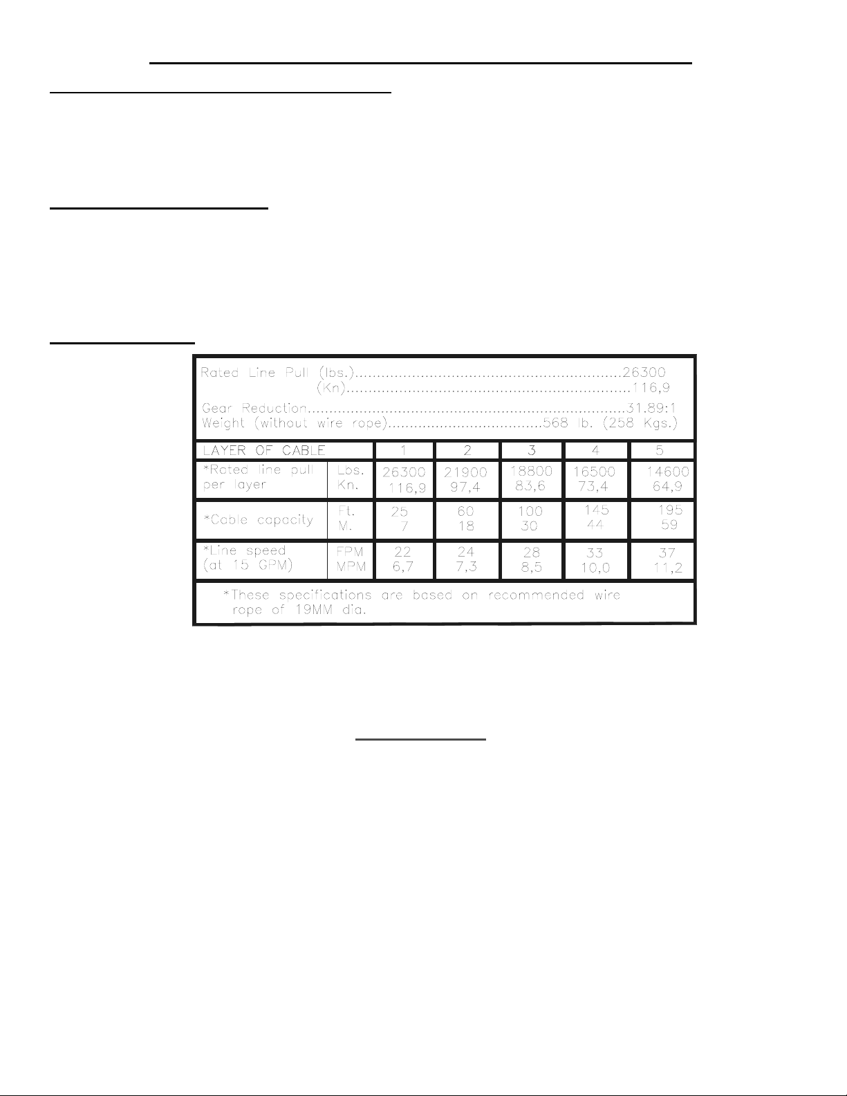
SPECIFICATIONS*
NOTE: The rated line pulls shown are for the winch only. Consult the wire rope manufacturer for wire rope ratings.
NOISE LEVEL 76 dB(A)
WARNINGS:
CLUTCH MUST BE TOTALLY ENGAGED BEFORE STARTING THE WINCHING OPERATION.
DO NOT START WINCH MOTOR BEFORE ENGAGING CLUTCH
DO NOT DISENGAGE CLUTCH UNDER LOAD.
STAY OUT FROM UNDER AND AWAY FROM RAISED LOADS.
STAND CLEAR OF CABLE WHILE PULLING. DO NOT TRY TO GUIDE CABLE.
DO NOT EXCEED MAXIMUM LINE PULL RATINGS SHOWN IN TABLE.
DO NOT USE WINCH TO LIFT, SUPPORT, OR OTHERWISE TRANSPORT PEOPLE.
A MINIMUM OF 5 WRAPS OF CABLE AROUND THE DRUM BARREL IS NECESSARY TO HOLD THE LOAD.
CABLE ANCHOR IS NOT DESIGNED TO HOLD LOAD.
1
Page 4
WINCH FRAME MOUNTING
B
A
BRAKE
PORT
MOTOR
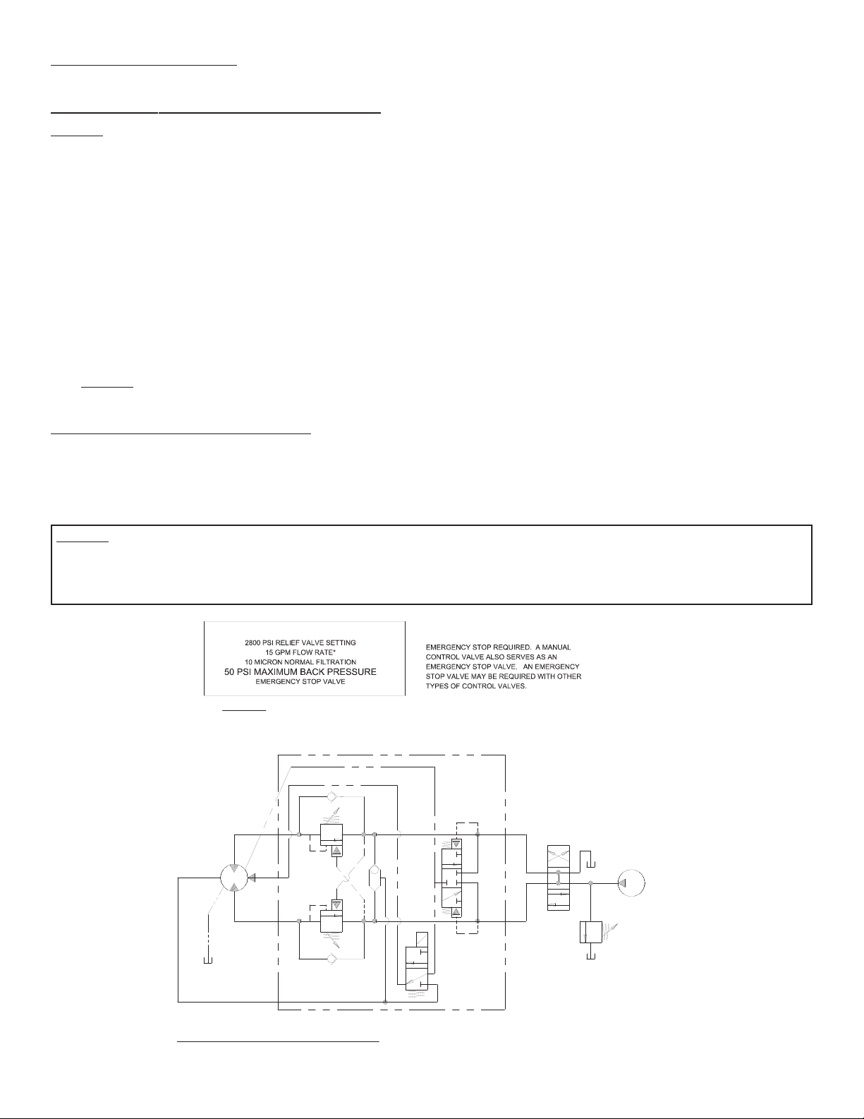
HYDRAULIC SYSTEM SCHEMATIC
SYSTEM
RELIEF
MAX. FLOW &
PRESSURE AT
RATED LOAD:
15 GPM
2800 PSI
PUMP
3 POSITION
4 WAY VALVE
(MOTOR SPOOL)
DUAL - A & B PORT
MOTOR CONTROL VALVE
WITH BRAKE RELEASE SHUTTLE
SYSTEM REQUIREMENTS:
*CAUTION: DO NOT EXCEED 20 GPM, IF EXCEEDED, MOTOR AND WINCH MAY BE DAMAGED
INSTALLER MUST DETERMINE TYPE OF
OPTIONAL
EXTERNAL
CASE DRAIN
LINE
Use (8) 5/8 inch diameter grade 5 or better bolts to attach mounting frame to wrecker.
CABLE INSTALLATION / TENSIONER OPERATION
CAUTION: The cable tensioner is not intended to be energized on a bare drum. Before applying air to the cable tensioner, engage the clutch
and run the winch in the reel in direction winding one full wrap of cable on the drum. This prevents damage to the cable tensioner.
1. Unwind cable by rolling it out along the ground to prevent kinking. Securely wrap end of wire rope, opposite hook, with plastic or similar
tape to prevent fraying.
2. Insert the end of cable, opposite hook end, into the hole in drum barrel. Secure cable to drum barrel, using setscrew furnished with
winch. TIGHTEN SETSCREW SECURELY.
3. Engage the clutch and carefully run the winch in the "reel-in" direction. Keeping tension on end of cable, spool about five wraps of cable
onto the drum and stop. Using a hammer, tap these five wraps tightly over against the cable anchor flange side of the cable drum. Finish
winding all the cable onto the cable drum. As cable winds onto the drum, watch the tensioner. Tensioner must be free to move without
obstruction to function properly. If tensioner touches any surrounding structure, correct the problem.
Adjust the Free-spool Effort of the Cable Tensioner
Disengage the winch clutch and free spool some cable off the drum. Adjust the air pressure to the cable tensioner to achieve the desired free
spool effort that also prevents "bird nesting" of the cable.
CAUTION: DO NOT EXCEED 80 PSI AIR PRESSURE TO THE AIR TENSIONER ACTUATORS.
Once you have adjusted the air pressure to the desired level, only minor adjustment may be required if your pressure regulator setting drifts.
HYDRAULIC SYSTEM REQUIREMENTS
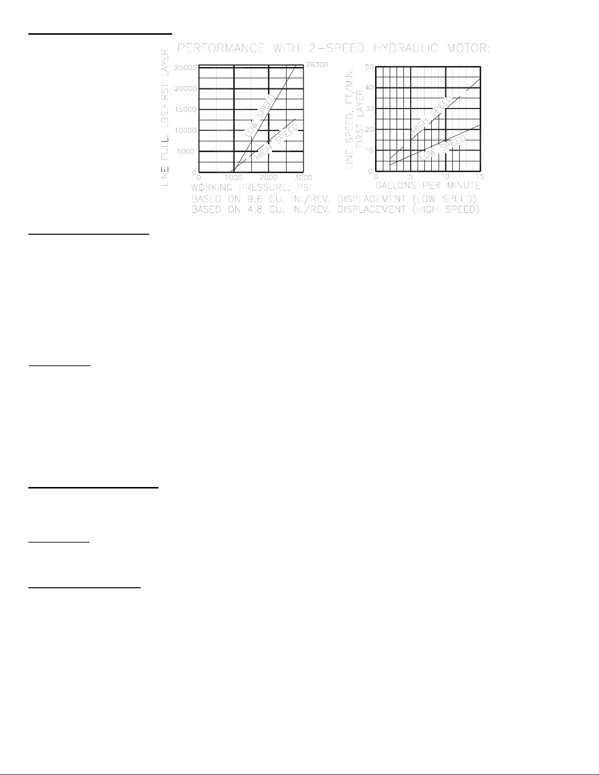
Refer to the performance charts, on page 3, to properly match your hydraulic system to RPH 30000T-117 winch performance. The charts
consist of :
(1) Line pull (lb.) first layer vs. working pressure (PSI) and (2) Line speed, first layer (FPM) vs. gallons per minute (GPM). Performance
based on a 2 speed motor displacement of 9.6/4.8 cubic inches with 15 GPM maximum flow rate. See page 14 for motor port size.
CAUTION: SYSTEM BACK PRESSURE MUST NOT EXCEED 50 PSI OR BRAKE SHAFT SEAL FAILURE CAN OCCUR. IF BACK PRESSURE
EXCEEDS 50 PSI, AND CANNOT BE REDUCED, AN EXTERNAL CASE DRAIN LINE SHOULD BE RUN FROM THE MOTOR CASE DRAIN PORT
(SEE PAGE 15) TO TANK OR A LINE/CONNECTION THAT HAS A PRESSURE BELOW 50 PSI. THE DRAIN LINE MUST BE ROUTED SO THAT
SOMEWHERE ALONG ITS PATH, THE LINE IS HIGHER THAN THE MOTOR SHAFT CENTERLINE.
2
Page 5
PERFORMANCE CHARTS
CLUTCH OPERATION
1. Move the clutch control valve to the "clutch-engaged" position.
2. Anytime the temperature is below freezing, run motor in the "cable out" direction only until the drum
starts to turn.
2a. In extreme cold temperatures (below 0o F/-18o C), pull out on the cable by hand only until
the drum starts to turn.
3. Wait at least 3 seconds for the clutch to fully engage, after which the winch is ready to winch in the
cable.
WARNING:
Do not attempt to engage the clutch by first running the winch motor and then moving the
clutch control valve to the "clutch-engaged" position while the motor is running. Do not start picking up
the load at the same time the clutch is being engaged.
To disengage clutch:
1. Run the winch in the "cable out" direction until the load is off the cable.
2.
Move the clutch control valve to the "clutch-disengaged" position.
3.
The cable may now be pulled off by hand.
2 SPEED OPERATIONS
Application of 12V or 24V DC, depending on your model, to the 2 speed selector valve will shift the
motor to high speed/low torque mode.
WARNING: DO NOT CHANGE SPEED SELECTOR WHEN WINCH IS IN OPERATION. DAMAGE TO
THE DRIVE TRAIN AND/OR MOTOR MAY RESULT.
WINCH OPERATION
The best way to get acquainted with how your winch operates is to make test runs before you actually use it.
Plan your test in advance. Remember, you hear your winch, as well as see it operate. Get to recognize the
sounds of a light steady pull, a heavy pull, and sounds caused by load jerking or shifting. Gain confidence in
operating your winch and its use will become second nature with you.
The uneven spooling of cable, while pulling a load, is not a problem, unless there is a cable pileup on one end of
drum. If this happens reverse the winch to relieve the load and move your anchor point further to the center of the
vehicle. After the job is done you can unspool and rewind for a neat lay of the cable.
3
Page 6

MAINTENANCE
Adhering to the following maintenance schedule will keep your winch in top condition and performing as it should with a minimum of repair.
A. WEEKLY
1. Check the oil level and maintain it to the oil level plug. If oil is leaking out, determine location and repair.
2. Check the pressure relief plug in top of the gear housing. Be sure that it is not plugged.
3. Lubricate cable with light oil.
B. MONTHLY
1. Check the winch mounting bolts. If any are missing, replace them and securely tighten any that are loose. Use grade 5 or better bolts.
2. Inspect the cable. If the cable has become frayed with broken strands, replace immediately.
C. ANNUALLY
1. Drain the oil from the winch annually or more often if winch is used frequently.
2. Fill the winch to the oil level plug with clean kerosene. Run the winch a few seconds with no load in the reel in direction. Drain the
kerosene from the winch.
3. Refill the winch to the oil level plug with all purpose SAE 80W-140 gear oil.
4. Inspect frame and surrounding structure for cracks or deformation.
TROUBLE SHOOTING GUIDE
CONDITIONS POSSIBLE CAUSE CORRECTION
OIL LEAKS FROM WINCH 1. Seals damaged or worn. 1. Replace seal.
2. Too much oil. 2. Drain excess oil. Refer to OPERATION.
3. Damaged gasket. 3. Replace gasket.
4. Replace brake, check back pressure to
4. Damaged brake shaft seal.
WINCH RUNS TOO SLOW 1. Low flow rate.
2. Hydraulic motor worn out. 2. Replace motor.
CABLE DRUM WILL NOT FREESPOOL 1. Clutch not disengaged.
BRAKE WILL NOT RELEASE 1. Air in hydraulic system. 1. Bleed air from brake. Refer to page 13.
motor. If back pressure is more than 50
PSI, reduce back pressure or add external case drain line.
1. Check flow rate.Refer to flow
HYDRAULIC SYSTEMS flow chart page
2.
1. Check air pressure to clutch cylinder 90
PSI minimum required-Refer to page 14.
4
Page 7

INSTRUCTIONS FOR OVERHAUL
1. Remove wire rope from winch. Disconnect hydraulic, air and electric lines. Remove winch and
frame from vehicle mounting.
Remove (2) nuts and washers (item #32 & #34) from air tensioner mounting bracket and
remove air tensioner assembly from winch frame. If air tensioner does not need service, move
on to STEP 2.
Loosen nuts (item #33) under air fittings and on opposite end of air actuators (item #52).
Loosen tube fittings (item #45 & #46) and remove tube (item #16), (it may be necessary to
rotate the fitting to obtain clearance to remove connecting tube). Remove the fittings. Remove
nuts to replace actuators. Actuator nut tightening torque should be no more than 10 ft.-lbs
each. Fitting should be no more than 1/4 turn beyond hand tight. Tensioner bar (item #6) is
held in place by 2 screws (item #21). Use a thread locking compound when replacing. Torque
to 30 ft-lbs each.
CABLE TENSIONER
ASSEMBLY
5
Page 8

2. Drain oil from gear housing (item #10) by removing plug (item #65) from end bearing. Remove
reducer and relief fitting (items #63 & #57).
If new air cylinder is required, remove air cylinder (item #49) from adapter (item #5) by removing
(4) capscrews (item #31). Remove breather vent (item #58) and pressure regulator (item #50).
Remove washer (item #37), nut and setscrew (items #38 & #29) and insert (item #43) from end of
air cylinder rod. Apply Loc-tite to threads of nut (item #38) and thread onto setscrew (item #29)
to 3/8 inch from drive end, as shown below. Apply Loc-tite to threads of setscrew and thread
insert (item #43) over end of setscrew and against nut. Use setscrew and nut to thread insert
(item #43) into end of air cylinder rod. Tighten nut against cylinder rod, keeping 3/8 inch distance
from drive end of setscrew to nut. Be sure breather vent (item #58), relief fitting (item #57), and
pressure regulator (item #50) are not damaged and in good operating condition. Remove and
replace if necessary.
Remove air cylinder adapter (item #5) and gasket (item #54) from gear housing cover by
unscrewing (4) capscrews (item #26).
3. Disconnect tube (item #69) from fitting (item #44) on brake (item #53). Remove motor (item #59)
and o-ring (item #62) by removing (4) capscrews (item #27). Remove valve (item #70), if
needed, from motor by removing (4) capscrews (item #22) and all connecting tubes and fittings.
6
Page 9

4. Remove brake assembly screws (item #28) from brake (item #53) and end bearing (item #11).
CAUTION
: Brake is spring loaded by clutch spring and must be restrained against end bearing as
mounting screws (item #28) are removed. Remove coupling (item #9) and gasket (item #56)
from end bearing. Take note of mounting configuration for proper mounting of parts during
re-assembly.
5. Remove winch from upright mounting frame (item #2) by removing capscrews (item #24 & #25),
lockwashers (item #35) and shoulder bolts (item #40 & #41). Pull motor end bearing (item #11)
from drum assembly (item #1).
7
Page 10

6. Pull drum assembly (item #1) upward from end bearing (item #10). Remove quad-rings (item #60
& #61) from grooves in drum bushings. Remove input shaft (item #13), clutch spring (item #68)
and washers (item #39 & #36) from end bearing (item #10).
Examine drum assembly (item #1) for signs of wear. If splines inside of drum driver (332162) are
damaged, drum driver must be replaced. Remove drum driver by unscrewing (8) capscrews
(414578). Place well oiled o-ring (462053) into drum driver groove and attach driver to drum
(332181) using (8) capscrews (414964). Torque capscrews to 114 ft. lbs. each, in criss-cross
pattern.
Press old bushings from drum and drum driver. Remove o-rings (462054 & 462052) from
grooves in drum and drum driver bushing (412088). Place well oiled o-rings (462054 & 462052)
into grooves in drum and outer diameter of drum driver bushing (412088). Press new bushing
(412087) into end of drum opposite drum driver and press bushing (412088) into drum driver until
flange of bushings are flush against drum and driver.
8
Page 11

7. Remove output coupling (item #8) and coupling shaft (item #7) from end bearing (item #10).
Examine bearings (item #17), pressed in output coupling (item #8), for signs of wear. Replace
bearings, if necessary, by pressing old bearings from coupling and press new bearings (item #17)
into each end of output coupling (item #8). Place coupling shaft (item #7) into bearings (item
#17).
8. Remove (12) capscrews (item #20) to pull gear housing cover from ring gear. Remove input
thrust washer, sun gear and carrier assemblies from inside of ring gear. Remove ring gear from
end bearing (item #10). Examine shifter shaft (item #14) for signs of wear, replace if necessary.
Examine bushing (item #19) for signs of wear. Replace bushing, if necessary, by pressing old
bushing from housing and pressing new bushing into place.
9
Page 12

9. NOTE: DETERMINE MOUNTING CONFIGURATION OF WINCH (R.H. or L.H. MOUNTED) BEFORE ATTACHING
UPRIGHT FRAME TO WINCH, TO ASSURE PARTS ARE MOUNTED TO PROPER SIDE, REFER TO WINCH
MOUNTING CONFIGURATIONS, STEP 15 PAGE 13.
Seat well oiled quad-rings (item #60 & #61) into groove of bushing in each end of drum assembly (item #1), as shown.
Carefully set drum assembly (item #1) down over motor end bearing (item #11). Lift gear housing end bearing (item
#10) and set into place on drum assembly. Attach upright frame (item #2) to end bearings. Install shoulder bolts
(item #40 & #41) and hand tighten. Install (4) capscrews with lockwashers (item #24 & #35) and (4) capscrews with
lockwashers (item #25 & #35), as shown. Tighten (4) inner-most capscrews securely, check rotation of cable drum.
Tighten (4) outer-most capscrews securely, check rotation of cable drum. Torque capscrews, in above inner-most
then outer-most pattern, to 250 ft. lbs. each. Torque (4) shoulder bolts to 30 ft. lbs. each. Make sure cable drum
assembly rotates freely at this point.
10. Liberally apply grease to splined ends of input shaft (item #13). Place (3) washers (item #39) and spring (item #68)
over longest splined end of shaft. Use grease to hold washer and spring in place on shaft and against snap ring
(item #67). Place spring (item #68) and longest splined end of shaft through motor end bearing (item #11) and drum
until shaft extends through bushing (item #19). Place clutch washer (item #36) over splined end of shaft and against
spring.
Place end of output coupling assembly (item #8), with longest spline inward, through end bearing bushing (item #19)
and mesh shaft coupling spline (item #7) with splined end of input shaft. Place short splined end of shifter shaft
(item #14) through washer (item #36) and into shaft coupling (item #7), meshing splines of shifter shaft with splines
in shaft coupling.
10
Page 13

11. Apply RTV sealing compound to ring gear mounting surface of end bearing (item #10). Place
ring gear onto end bearing, aligning holes in ring gear with holes and gear housing end bearing.
Use (2) capscrews to temporarily secure ring gear to end bearing.
Place (2) gear carrier assemblies into ring gear meshing carrier gears with ring gear. Remove
(2) temporary capscrews, making sure that ring gear and carrier assemblies are securely against
end bearing (item #10). Apply RTV sealing compound to cover mounting surface of ring gear
(item #4) and attach cover to ring gear. Use (12) capscrews (item #20) to secure gear box to
gear housing end bearing. Torque capscrews to 39 ft. lbs. each, in criss-cross pattern.
12. Slide input sun gear over shifter shaft (item #14) and mesh with teeth of input carrier. Apply
grease to input thrust washer and place into slots of air cylinder adapter (item #5). Place gasket
(item #54) into position on gear box cover with sealer and attach adapter to cover using (4)
capscrews (item #26). Apply Loctite PST thread sealer to threads of capscrews. Torque
capscrews to 13 ft. lbs. each, in criss-cross pattern.
Pull rod from air cylinder as far as possible. Slide washer (item #37) over setscrew (item #29)
and against nut attached to air cylinder rod. Place setscrew into hole of shifter shaft (item #14).
Attach new air cylinder (item #49) and gasket (item #55) with sealer, to adapter using (4)
capscrews (item #31). Apply Loctite PST thread sealer to threads of capscrews. Torque
capscrews to 5 ft. lbs. each, in criss-cross pattern.
11
Page 14

13. With pin (item #66) installed in coupling, align splines of coupling (item #9) with splines of input shaft below. Slide
coupling over end of shaft (item #13). Place gasket (Item #56) into position on motor mounting surface of end
bearing (item #9). Insert brake shaft into coupling. Use (2) screws (item #28) to attach brake assembly to motor end
bearing. Alternately tighten one, then the other of the capscrews (item #28) in a back and forth manner, thus
compressing spring (item #68) and pulling the brake assembly down against end bearing (item #11). Torque
capscrews to 85 ft lbs each.
14.
Attach control valve (item #70) with (4) o-rings (supplied with valve) to motor (item #59) using (4) capscrews (item
#22).
Attach motor (item #59) with o-ring (item #62) to brake (item #53). Use (4) capscrews (item #27) and torque to 74
ft. lbs. each. Securely connect tube (item #69) to fitting (item #44) on brake (item #53) and to elbow fitting (item
#48) .
12
Page 15

15. Apply Permatex to threads of plug (item #65). Thread plug into tapped hole in bottom of gear housing end
bearing (item #10). Pour approx. 2.50 pints of SAE 80W-140 oil into end bearing. Check oil level by
removing oil level plug noted below. Insert relief fitting (item #57) and thread reducer (item #63) into end
bearing at oil fill hole. Install tensioner assembly to winch frame, center the tension bar between the drum
flanges with a scale or tape measure and tighten the mounting hardware (item #32 & #34) to 75 ft-lbs.
each.
Install winch and connect hydraulic lines and install cable.
WARNING: The cable tensioner is not intended to be energized on a bare drum. Before applying
air to the cable tensioner, engage the clutch and run the winch in the reel in direction winding one
full wrap of cable on the drum. This prevents damage to the cable tensioner.
16. Check proper operation of clutch by applying air pressure to clutch air cylinder to disengage clutch. Verify
that winch freespools. Re-engage clutch. A loud noise should be heard when clutch engages. Winch drum
should not freespool.
17. Operate winch forward and reverse to verify that drum rotates.
18. Unwind cable by rolling it out along the ground to prevent kinking. Securely wrap end of wire rope, opposite hook, with plastic or similar tape to prevent fraying.
Insert the end of cable, opposite hook end, into the hole in drum barrel. Secure cable to drum barrel,
using setscrew furnished with winch. TIGHTEN SETSCREW SECURELY.
Engage the clutch and carefully run the winch in the “reel-in” direction. Keeping tension on end of cable,
spool about five wraps of cable onto the drum and stop. Using a hammer, tap these five wraps tightly over
against the cable anchor flange side of the cable drum. Finish winding all the cable onto the cable drum.
As cable winds onto the drum, watch the tensioner. Tensioner must be free to move without obstruction to
function properly. If tensioner touches any surrounding structure, correct the problem.
CAUTION: DO NOT EXCEED 80 PSI AIR PRESSURE TO THE AIR TENSIONER ACTUATORS.
13
Page 16

OPERATION
Adjust the free-spool effort of the cable tensioner. Disengage the winch clutch and free spool some cable off
the drum. Adjust the air pressure to the cable tensioner to achieve the desired free spool effort that also prevents “bird nesting” of the cable.
Once you have adjusted the air pressure to the desired level, only minor adjustment may be required if your
pressure regulator setting drifts.
14
Page 17

1.052 SAE STRAIGHT
THREAD O-RING PORT
(TYP 2 PLACES
OPPOSITE SIDES)
9/16-18 O-RING
CASE DRAIN PORT
15
Page 18

16
Page 19

DESCRIPTIONPART NO.
QTY.
ITEMDESCRIPTIONPART NO.
PARTS LIST
RPH 30000T-117
40 2 418453 SHOULDER BOLT 1/2 X 3/4 LG. 3/8-16
41 2 418456 SHOULDER BOLT 1/2 X 1-1/2 LG. 3/8-16
42 2 424005 COTTER PIN 1/8 DIA. X 1 LG
43 1 426045 INSERT-THREADED 5/16-24NF
44 1 432023 FITTING HYD. 7/16-20 STRAIGHT
45 1 432032 FITTING-TEE
46 1 432033 FITTING 90 DEG. ELBOW
47 1 432034 FITTING 1/8-27 NPT
48 1 FITTING-90 DEG. ELBOW (PARKER #2503-4-4)
49 1 433014 AIR CYLINDER
50 1 433015 REGULATOR-AIR PRESS, PRESET
51 1 433020 REGULATOR-AIR PRESS, ADJUSTABLE
52 2 433022 AIR ACTUATOR
53 1 438023 BRAKE
54 1 442216 GASKET-AIR CYL. ADAPTER
55 1 442217 GASKET-AIR CYL.
56 1 442224 GASKET-BRAKE
57 1 456008 RELIEF FITTTING
58 1 456038 FITTING-BREATHER VENT
1 516025 VALVE-MOTOR CONTROL (12 VOLT)
59 1 458096 MOTOR 2-SPD, 9.6/4.8CID
60 1 462013 QUAD-RING 2-7/8 OD X 2-1/2 I D X 3/16
61 1 462050 QUAD-RING
62 1 462062 O-RING
63 1 468004 REDUCER 1/2-1/8NPTF
64 2 468016 PIPE PLUG 1/8-27NPTF HEX SOC. HD.
65 1 468019 PIPE PLUG 1/2-14NPTF HEX SOC HD.
66 1 470091 PIN-SPRING
67 1 490038 SNAP RING
68 1 494108 SPRING-CLUTCH SHIFTER .192 DIA
69 1 509015 TUBE ASSY-HYDRAULIC BRAKE RELEASE
70 1 516024 VALVE-MOTOR CONTROL (24 VOLT)
QTY.
1 1 234183 DRUM ASSY.
2 1 242165 ASSY-FRAME, WINCH MTG
3 1 265021 TENSIONER-LEVER
4 1 296433 GEAR BOX ASSY.
5 1 300069 ADAPTER-AIR CYLINDER.
6 1 304172 BAR-AIR TENSIONER
7 1 324286 COUPLING-SHAFT, 1.375 DIA.
8 1 324288 COUPLING-OUTPUT
9 1 324298 COUPLING-BRAKE
10 1 338293 END BEARING-GEAR HSG.
11 1 338311 END BEARING-MOTOR
12 1 346046 PIN-PIVOT
13 1 357506 SHAFT-INPUT
14 1 358065 SHAFT-INPUT SHIFTER
15 1 365037 TUBE-STAINLESS, AIR TENS. REGULATOR
16 1 365038 TUBE-STAINLESS, 1/4"DIA, AIR TENSIONER
17 2 402119 BEARING
18 1 408227 BRACKET-ASSY. AIR TENSIONER
19 1 412086 BUSHING-THRUST, GEAR HSG.
20 12 414272 SCREW 3/8-16NC X 5-1/2 HXHD, GR5.
21 2 414278 CAPSCREW 3/8-16NC X 3/4 LG. HXHD Z/P GR5
22 4 414400 CAPSCREW 3/8-24NF X 4 LG. HX.HD. GR.8
23 2 414548 CAPSCREW 1/2-13NC X 1-1/2 HX HD Z/P GR5
24 4 414750 CAPSCREW 3/4-10NC X 1-1/2 LG HX HD GR5
25 4 414754 CAPSCREW 3/4-10NC X 2-1/2 LG, HX HD GR5
26 4 414864 CAPSCREW 5/16-18NC X 3/4 LG HX. SOC HD
27 4 414948 CAPSCREW 1/2-13NC X 1-1/4 LG. HX. SOC. HD
28 2 414958 CAPSCREW 1/2-13NC X 4 LG. HX. SOC. HD
29 1 416051 SETSCREW 5/16-24NF X 1 LG. SOC. HD. CUP
30 1 416059 SETSCREW 3/8-16NC X 1/2 LG. HX. SOC. HD. CUP
31 4 416233 SCREW-#10-24NC X 2 1/2 HX. SOC. HD.
32 2 418069 NUT 1/2-13NC HEX REG. Z/P
33 4 418080 NUT 5/8-11NC REG HEX Z/P
34 4 418223 WASHER 1/2 USS FLAT Z/P
ITEM
35 8 418249 LOCKWASHER 3/4 ID MED SECT. Z/ P
36 2 418462 WASHER
37 1 418432 WASHER-THRUST 5/16 ID
38 1 418433 NUT-LOCK 5/16-24NF X 3/16 THK.
39 3 418441 WASHER
17
Page 20

LIMITED WARRANTY
OM-914008-0105-J
RAMSEY WINCH warrants each new RAMSEY Winch to be free from defects in
material and workmanship for a period of one (1) year from date of purchase.
The obligation under this warranty, statutory or otherwise, is limited to the
replacement or repair at the Manufacturer's factory, or at a point designated by the
Manufacturer, of such part that shall appear to the Manufacturer, upon inspection
of such part, to have been defective in material or workmanship.
This warranty does not obligate RAMSEY WINCH to bear the cost of labor or
transportation charges in connection with the replacement or repair of defective
parts, nor shall it apply to a product upon which repair or alterations have been
made, unless authorized by Manufacturer, or for equipment misused, neglected or
which has not been installed correctly.
RAMSEY WINCH shall in no event be liable for special or consequential damages.
RAMSEY WINCH makes no warranty in respect to accessories such as being
subject to the warranties of their respective manufacturers.
RAMSEY WINCH, whose policy is one of continuous improvement, reserves the
right to improve its products through changes in design or materials as it may
deem desirable without being obligated to incorporate such changes in products of
prior manufacture.
RAMSEY WINCH COMPANY
Post Office Box 581510 Tulsa, Oklahoma 74158-1510
Telephone: (918) 438-2760 FAX: (918) 438-6688
OM-914008-0503-H
 Loading...