

Page 1

Page 2

Page 3

Page 4
WINCH FRAME MOUNTING
Use (8) 5/8 inch diameter grade 5 or better bolts to attach mounting frame to wrecker.
CABLE INSTALLATION
1. Unwind cable by rolling it out along the ground to prevent kinking. Securely wrap end of
wire rope, opposite hook, with plastic or similar tape to prevent fraying.
2. Insert the end of cable, opposite hook end, into the hole in drum barrel. Secure cable to
drum barrel using setscrew furnished with winch. TIGHTEN SCREW SECURELY.
3. Carefully run the winch in the “reel-in” direction. Keeping the tension on the end of cable,
spool all the cable onto the cable drum, taking care to form neatly wrapped layers.
HYDRAULIC SYSTEM REQUIREMENTS
Refer to the performance charts below to properly match your hydraulic system to RPH 30000
winch performance. The charts consist of:
(1) Line pull (lbs.) first layer, vs. working pressure (PSI) and (2) Line speed, first layer (FPM)
vs. gallons per minute (GPM). Performance based on a motor displacement of 9.6 cubic
inches with 15 GPM maximum flow rate. See page 13 for motor port size.
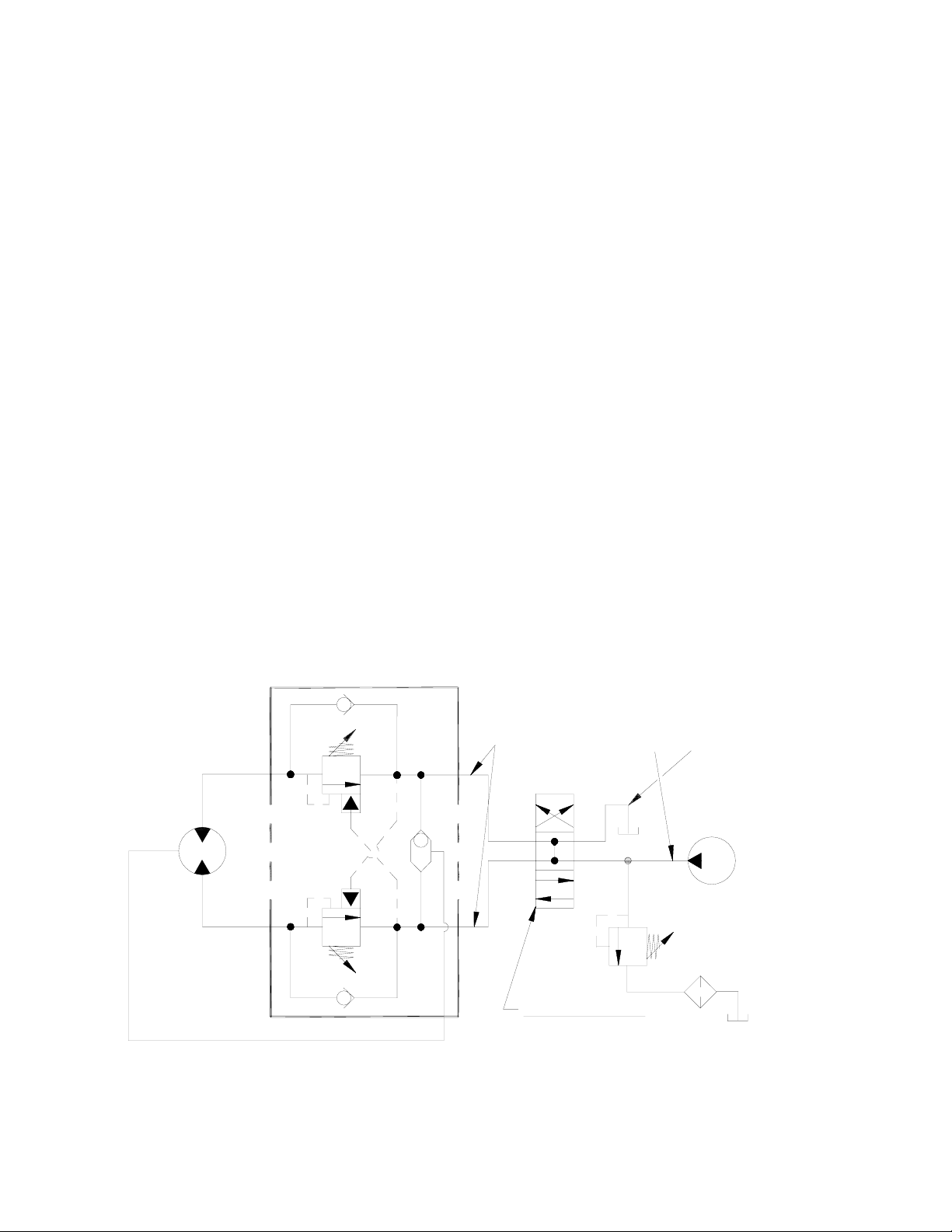
TYPICAL LAYOUT
DUAL-A & B PORT CONTROL
WITH BRAKE RELEASE SHUTTLE
MOTOR
BRAKE
PORT
A
B
HIGH PRESSURE LINE
CONTROL VALVE
3 POSITION
4 WAY VALVE
(MOTOR SPOOL)
LOW PRESSURE LINE
PUMP
2
Page 5

Page 6

Page 7

Page 8

3. Remove brake assembly screws (item #48) from brake (item #33a) to access mounting screws (item #20)
attaching brake adapter plate (item #33d) to end bearing (item #9). Caution: Brake is spring loaded by
clutch spring and must be restrained against end bearing as mounting screws are removed. Remove coupling (item #7) and gasket (item #33e) from the end bearing. Take note of the mounting configuration for
proper mounting of parts during re-assembly.
48
20
33c
33e
33d
48
31
33a
20
33e
9
7
6
Page 9

Page 10

Page 11

Page 12

Page 13

12. Align key way of coupling with key on end of input shaft inside end bearing assembly. Slide coupling over
end of shaft. Place gasket (item #33e) into position on motor mounting surface of end bearing (item #9).
Use (2) screws (item #20) to attach adapter plate (item #33d) to motor end bearing. Torque capscrews to
85 ft-lbs. each. Place second gasket (item #33e) on adapter plate. Insert brake shaft with key (item #33c)
into coupling. Re-attach brake (item #33a) to adapter plate using brake assembly screws (item #48).
Torque capscrews to 97 ft-lbs. each.
Note: Care must be taken to assure brake assembly and adapter plate are seated properly prior to installing assembly bolts (item #48). Damage will occur to rotor stack or shaft snap ring if not properly installed.
48
20
33c
33e
33d
48
31
33a
33e
9
7
20
11
Page 14

15.Check proper operation of clutch by applying air pressure to clutch air cylinder to disengage
clutch. Verify that winch freespools. Re-engage clutch. A loud noise should be heard when clutch
engages. Winch drum should not freespool.
16.Operate winch forward and reverse to verify that drum rotates.
12
Page 15

13
Page 16

NOTES
Page 17

15
Page 18

16
Page 19

FITTING-HYD 7/16-20 90º ELBOX
PARTS LIST RPH 30,0000
1 1 234167 DRUM ASSEMBLY 29 1 426045 INSERT
2 1 242156 UPRIGHT MOUNTING FRAME 30 1 432018
3 1 296433 GEAR BOX 31 1 432023 FITTING 7/16-20 STRAIGHT UNION
4 1 300069 ADAPTER-AIR CYLINDER 32 1 433014 AIR CYLINDER
5 1 416059 SETSCREW - 3/8-16NC X 1/2 LG CUT POINT 33 1 438037 BRAKE ASSEMBLY
6 1 324286 COUPLING-SHAFT 33a 1 BRAKE
7 1 324287 COUPLING-BRAKE 33b 1 MOTOR GASKET*
8 1 324288 COUPLING-OUTPUT 33c 1 BRAKE SHAFT KEY
9 1 338292 END BEARING-MOTOR 33d 1 ADAPTER PLATE
10 1 338293 END BEARING-GEAR 33e 2 ADAPTER PLATE GASKET*
11 1 342081 KEY 34 1 442217* GASKET-AIR CYLINDER
12 1 357493 SHAFT-INPUT
13 1 358065 SHIFTER SHAFT 36 1 442216* GASKET-ADAPTER
14 2 402119 BEARING 37 1 456008 RELIEF FITTING
15 1 412086 BUSHING-THRUST 38 1 456038 BREATHER VENT
16 12 414272 CAPSCREW 3/8-16NC X 5-1/2 LG HX HD GR5 39 1 458076 MOTOR-HYD.
17 8 414777 CAPSCREW 3/4-10NC X 1-3/4 LG HX HD GR5 40 1 462013* QUAD RING
18 4 414864 CAPSCREW 5/16-18NC X 2-3/4 LG HX SOC HD 41 1 462050* QUAD RING
19 3 414935 CAPSCREW 3/8-16NC X 2-1/2 LG HX SOC HD 42 1 468004 REDUCER
20 2 414947 CAPSCREW 1/2-13NC X 1 LG SOC HD 43 1 468019 PIPE PLUG
21 2 414948 CAPSCREW 1/2-13NC X 1-1/4 LG SOC HD 44 1 470089 PIN
22 1 416051 SETSCREW - 5/16-24NC X 1 LG SOC HD 45 1 494108 SPRING
23 4 416233 SETSCREW - #10-24NC X 2-1/2 LG HX SOC 46 1 509020 TUBE ASSEMBLY
24 8 418249 LOCKWASHER 3/4 MED SECT. 47 1 516011 VALVE-CONTROL
25 2 418462 THRUST WASHER 48 2 414595 CAPSCREW - 1/2-13NC X 3 1/2 HD HD GR8
26 1 418432 THRUST WASHER
27 1 418433 NUT - 5/16-24NC X 3/16 THK LOCK
28 4 418453 SHOULDER BOLT
Item No. Qty. Part No. Description Item No. Qty. Part No. Description
* THESE ITEMS ARE PART OF SEAL AND GASKET KIT #246046. ALSO INCLUDED ARE (3) O-RINGS USED IN DRUM ASSEMBLY 234167, REFER TO PAGE 7.
17
Page 20

OM-912451-0307-M
 Loading...