

Page 1
GEARBOX REPLACEMENT KIT
#256115
INSTALLATION INSTRUCTIONS
FOR RPH 20000/25000 WINCHES
WITH AUBURN GEARBOXES
NOTE: Refer to pages 7 and 8 for complete parts list and exploded parts diagram of winch with replacement
(Quantum) gearbox and associated parts. Item numbers denoted with * are from the Gearbox Replacement
kit. See parts list for kit on page 6.
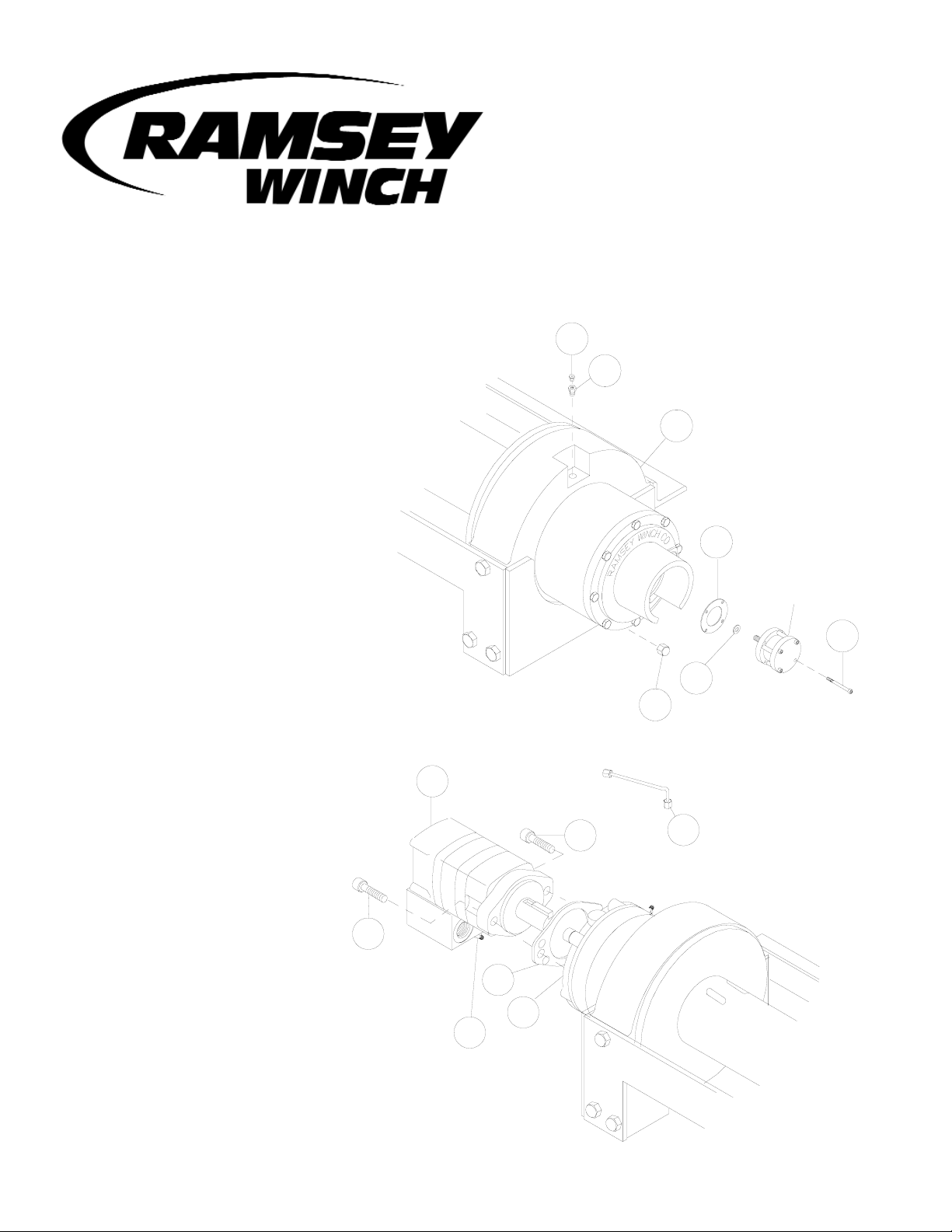
1. Drain oil from gear end housing (item
#9) by removing pipe cap (item #44)
from pipe nipple in end bearing. Remove
reducer (item #42) and relief fitting (item
#36). Set aside pipe cap, reducer, and
relief fitting.
Remove air cylinder from gear end by
removing 4 screws (item #24). Pull air
cylinder from gear end assembly. Make
sure washer (item #26) comes off with
air cylinder. Set aside air cylinder and
washer.
2. Disconnect tube (item #47) from
elbows (item #30), as shown.
Remove motor (item #38) and
gasket (item #33) by removing
(2) capscrews (item #19).
AIR CYLINDER
9
36
42
34
44
26
24
33
38
19
19
47
32
30
Page 2
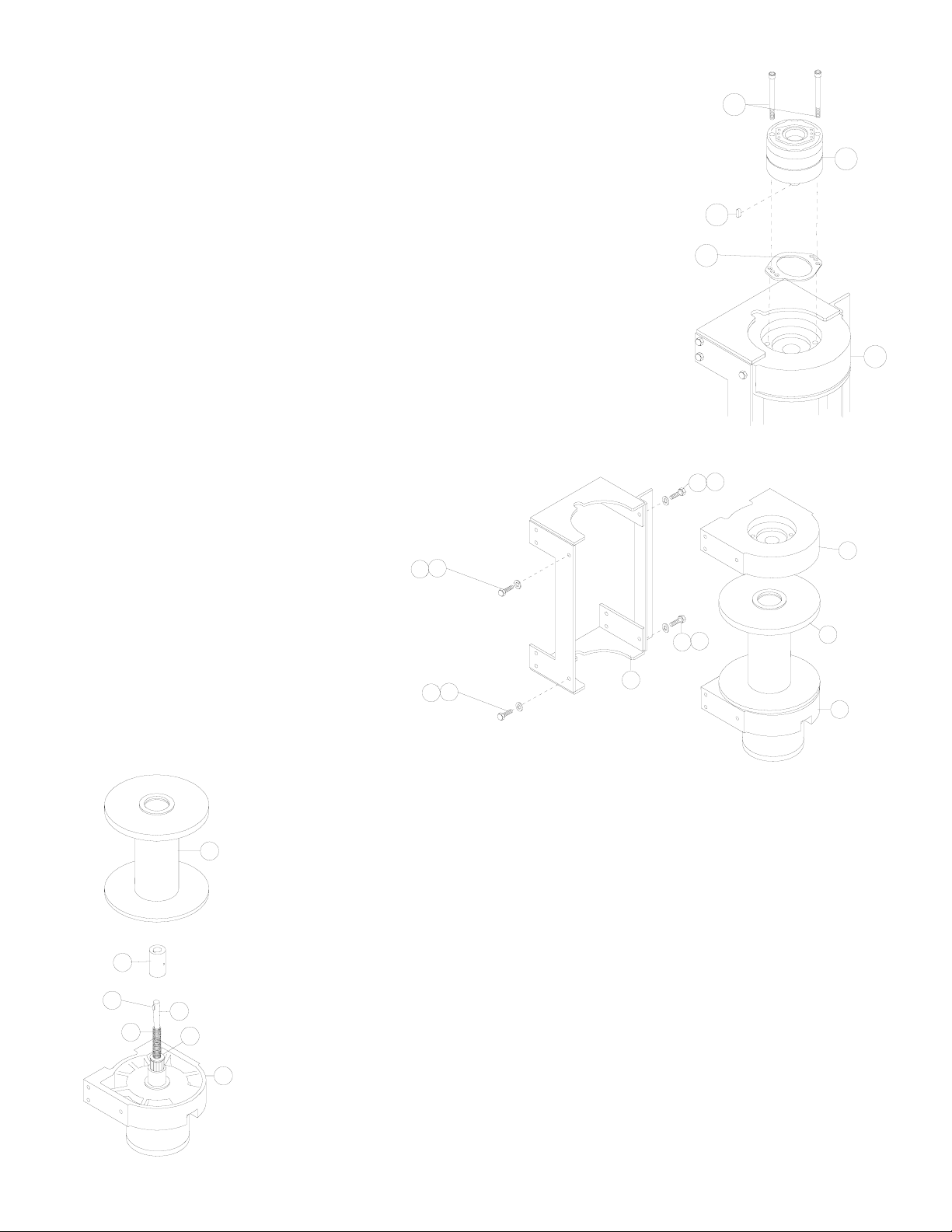
3. Remove brake assembly (item #32) by removing (2) mounting screws (item
#20) that attach brake to end bearing (item #8). Remove gasket (item #35)
from end bearing.
4. Take note of mounting configuration
for proper mounting of parts during
re-assembly. Remove winch from upright
mounting frame (item #2) by removing
(4) capscrews and lockwashers. Pull
motor end bearing (item #8) from drum
assembly (item #1).
10
8
20
32
35
2
9
1
8
17
25
17
25
25
16
25
16
2
11
9
10
1
5
46
28
5. Pull drum assembly (item #1) upward from end bearing (item #9). Remove
coupling (item #5), input shaft (item #11), and clutch spring (item #46) from
gear end assembly.
Set aside drum assembly, coupling, input shaft, and clutch spring.
Discard gear end assembly.
Page 3

6. From new Gearbox Replacement kit, place Gear End Assembly (item
#2*) on workbench with gearbox cover down (as shown at right).
Slide shifter shaft (item #4*) with washer (item #5) over it into the
Gear End Assembly, with long splined end going in first. Mesh
splines with input sun gear in gearbox. About 1/2” of the end of the
shifter shaft should protrude through gearbox cover when it is all the
way in.
Insert the shaft coupling (item #3*) into the shifter shaft and then
insert the output coupling assembly (item #1*) over it.
Place a second washer (item #5*) on the output coupling assembly.
7. Insert the input shaft (item #11), clutch spring (item #46), and coupling
(item #5) into the gear end assembly. Carefully set drum assembly (item
#1) on gear end assembly.
Secure drum to gear end assembly using C-clamp.
3
5*
1*
3*
5*
4*
2*
Item numbers denoted with * are from
the Gearbox Replacement kit.
10
11
1
5
46
5*
Page 4

8. Carefully set motor end bearing on
drum assembly. Secure motor end
bearing to drum using C-clamp.
Install winch in upright mounting frame
using 4 capscrews (items #16 &
#17) and lockwashers (item #24).
Tighten securely.
9. Place gasket (Item #8*) into position on motor mounting surface of end
bearing (item #8). Insert brake shaft into coupling. Use (2) screws (item
#20) to attach brake assembly to motor end bearing. Torque capscrews
to 85 ft lbs each.
2
1
8
16
25
16
25
17
25
17
25
8*
10
8
20
32
4
Page 5

10.Attach motor (item #38) with well oiled
gasket (item #7*) to brake (item #32).
Use (2) capscrews (item #19) and torque
to 74 ft. lbs. each. Securely connect tube
(item #47) to elbow (item #30), in valve,
and brake (item #32).
11.Slide washer (item #26) over setscrew and
against nut attached to air cylinder rod.
Install air cylinder into gearbox cover making sure the setscrew in end of cylinder rod
goes in hole in end of shifter shaft. Apply
Loc-tite PST thread sealer to threads of capscrews (item #24). Attach air cylinder and
new gasket (item #6*) to end bearing
assembly using (4) capscrews (item #24).
Torque capscrews to 60 in-lbs. each, in
criss-cross pattern.
Apply Permatex to threads of pipe cap (item
#44). Thread pipe cap onto pipe nipple in
bottom of gear housing end bearing. Pour
approx. 1.75 pints of SAE 80W-140 oil into
end bearing. Insert relief fitting (item #36)
and thread reducer (item #42) into end
bearing at oil fill hole.
Install winch and connect pressure lines.
Disengage clutch and verify that winch
freespools. Engage clutch and run winch to
verify that clutch fully engages and that
drum rotates in both directions.
7*
38
19
47
19
30
32
5
AIR CYLINDER
44
26
6*
42
36
24
OIL FILL LEVEL
Page 6

Kit #256115 Parts List
1
3
2
6
5
5
4
7
8
Item
No.
Qty. Part No. Description
1 1 296575 OUTPUT COUPLING ASSY
2 1 296609 GEAR END ASSY
3 1 324294 COUPLING - SHAFT
4 1 358073 SHIFTER SHAFT
5 2 418462 CLUTCH WASHER
6 1 442217 GASKET - AIR CYLINDER
7 1 442215 GASKET - BRAKE & MOTOR END
8 1 442224 GASKET - BRAKE OUTPUT FACE
PARTS LIST
RAMSEY WINCH COMPANY
P.O. Box 581510• Tulsa OK 74158-1510
Telephone: (918) 438-2760 • Fax: (918) 438-6688
Visit us at www.ramsey.com
914080-0903-A
6
Page 7

8
10
Winch Assembly
1
4
LONGEST SPLINE
5
10
11
7
6
9
2
3
24
31
23
34
13
15
42
36
22
28
14
14
28
41
43
44
21
26
27
29
37
38
19
19
47
20
33
35
46
40
39
25
17
45
32
30
20
30
18
48
25
16
7
Page 8

ITEM QTY. PART NO. DESCRIPTION ITEM QTY. PART NO. DESCRIPTION
1 1 242157 ASSY-FRAME 25 12 418218 LOCKWASHER 1/2 MED SECT
2 1 234170 DRUM ASSEMBLY 26 1 418432 WASHER - THRUST
3 1 296504 GEAR BOX 27 1 418433 NUT - 5/16-24 NF X 3/16 THK LOCK
4 1 314010 CABLE ANCHOR 28 2 418462 WASHER - CLUTCH
5 1 324290 COUPLING - BRAKE 29 1 426045 INSERT
6 1 324294 COUPLING - SHAFT 30 2 432018 FITTING - HYD 7/16-20 90° ELBOW
7 1 324299 COUPLING - OUTPUT 31 1 433014 AIR CYLINDER
8 1 338294 END BEARING - MOTOR 32 1 438020 BRAKE
9 1 338315 END BEARING - GEAR 33 1 442215 GASKET - BRAKE & MOTOR END*
10 2 342194 KEY - RD END 34 1 442217 GASKET - AIR CYLINDER*
11 1 357496 SHAFT - INPUT 35 1 442224 GASKET - BRAKE OUTPUT FACE*
12 1 358073 SHIFTER SHAFT 36 1 456008 RELIEF FITTING
13 1 362269 SPACER 37 1 456038 BREATHER VENT
14 2 402119 BEARING 38 1 458081 MOTOR - HYDRAULIC
15 1 412090 BUSHING - THRUST 39 1 462012 QUAD. RING*
16 10 414561 CAPSCREW ½-13 NC X 1-1/4 LG HX HD GR 5 40 1 462050 QUAD. RING*
17 2 414564 CAPSCREW ½-13 NC X 1-1/2 LG HX HD GR 5 41 1 468017 PIPE PLUG
18 3 414935 CAPSCREW 3/8-16NC X 2-1/2 LG HX SOC HD 42 1 468024 REDUCER
19 2 414948 CAPSCREW 1/2-13NC X 1-1/4 LG SOC HD 43 1 468036 PIPE NIPPLE
20 2 414958 CAPSCREW 1/2-13NC X 4 LG SOC HD 44 1 468037 PIPE CAP
21 8 415152 BOLT - M8-1.25X30MM LG. HX HD GR 8.8 Z/P 45 1 470091 PIN
22 12 415207 BOLT - M10-1.25X60MM LG. HX HD GR 8.8 Z/P 46 1 494108 SPRING
23 1 416051 SETSCREW 5/16-24 NF X 1 LG SOC HD 47 1 509006 TUBE ASSEMBLY
24 4 416233 CAPSCREW #10-24NC X 2-1/2 LG HX SOC HD 48 1 516011 CONTROL VALVE
PARTS LIST
8
 Loading...