

Page 1
OPERATING, SERVICE AND
MAINTENANCE MANUAL
MODEL RPH-20,000 INDUSTRIAL
PLANETARY WINCH
CAUTION: READ AND UNDERSTAND THIS MANUAL BEFORE INSTALLATION
AND OPERATION OF WINCH. SEE WARNINGS!
Page 2

TABLE OF CONTENTS
INTRODUCTION...................................................................................................... 1
WARRANTY INFORMATION .................................................................................. 1
SPECIFICATIONS ................................................................................................... 1
WARNINGS ............................................................................................................. 1
WINCH FRAME MOUNTING................................................................................... 2
CABLE INSTALLATION........................................................................................... 2
HYDRAULIC SYSTEM REQUIREMENTS ..............................................................2
PERFORMANCE CHARTS .....................................................................................3
CLUTCH OPERATION ............................................................................................3
WINCH OPERATION............................................................................................... 3
MAINTENANCE ....................................................................................................... 4
TROUBLE SHOOTING GUIDE ............................................................................... 4
INSTRUCTIONS FOR OVERHAUL......................................................................... 5-12
MOUNTING CONFIGURATIONS............................................................................12
DIMENSIONAL DRAWING...................................................................................... 13
PARTS LIST AND PART DRAWING....................................................................... 14-15
LIMITED WARRANTY ............................................................................................. 16
Page 3
RAMSEY HYDRAULIC PLANETARY WINCH MODEL RPH 20,000
PLEASE READ THIS MANUAL CAREFULLY
This manual contains useful ideas in obtaining the most efficient operation from your Ramsey Winch, and safety
procedures one needs to know before operating a Ramsey Winch. Do not operate this winch until you have carefully
read and understand the "WARNINGS" and "OPERATION" sections of this manual.
WARRANTY INFORMATION
Ramsey Winches are designed and built to exacting specifications. Great care and skill go into every winch we make.
If the need should arise, warranty procedure is outlined on the back of your self-addressed postage paid warranty card.
Please read and fill out the enclosed warranty card and send it to Ramsey Winch Company. If you have any problems
with our winch, please follow instructions for prompt service on all warranty claims. Refer to back page for limited
warranty.
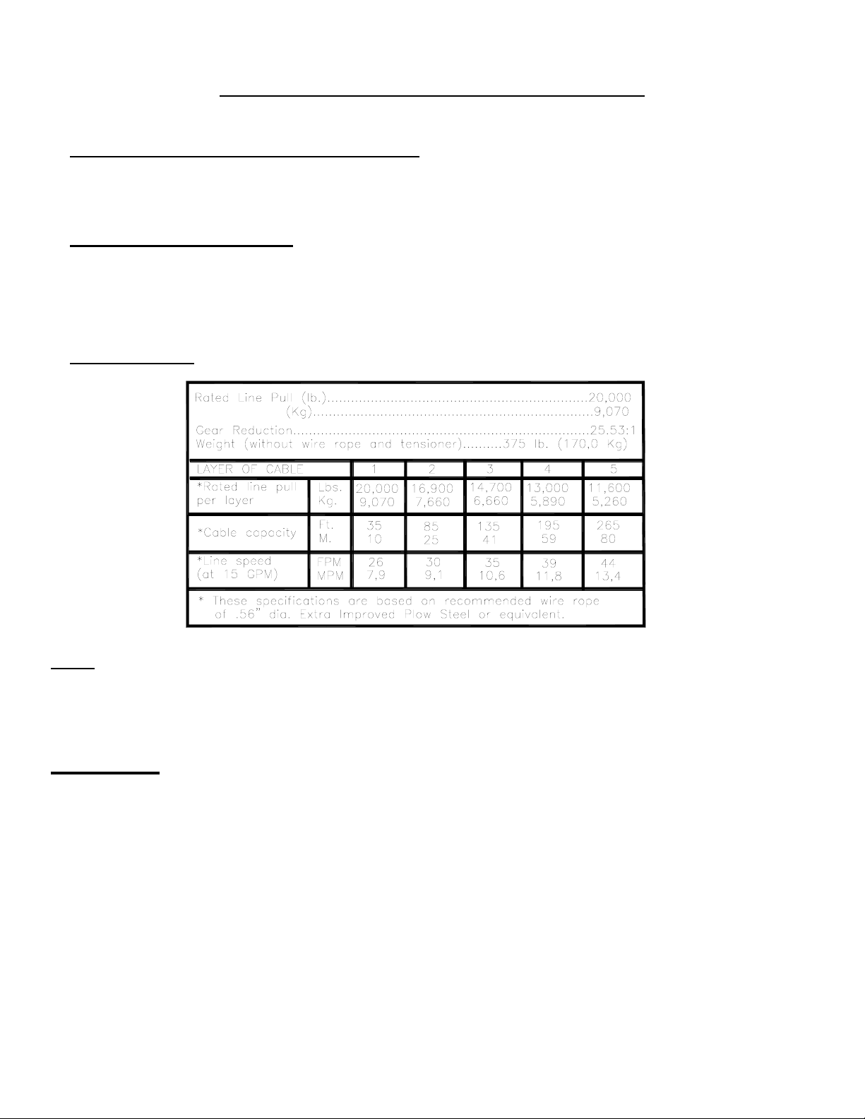
SPECIFICATIONS*
NOTE:
The rated line pulls shown are for the winch only. Consult the wire rope manufacturer for wire rope ratings.
WARNINGS:
CLUTCH MUST BE TOTALLY ENGAGED BEFORE STARTING THE WINCHING OPERATION.
DO NOT START WINCH MOTOR BEFORE ENGAGING CLUTCH.
DO NOT DISENGAGE CLUTCH UNDER LOAD.
STAY OUT FROM UNDER AND AWAY FROM RAISED LOADS.
STAND CLEAR OF CABLE WHILE PULLING. DO NOT TRY TO GUIDE CABLE.
DO NOT EXCEED MAXIMUM LINE PULL RATINGS SHOWN IN TABLE.
DO NOT USE WINCH TO LIFT, SUPPORT, OR OTHERWISE TRANSPORT PEOPLE.
A MINIMUM OF 5 WRAPS OF CABLE AROUND THE DRUM BARREL IS NECESSARY TO HOLD THE LOAD.
CABLE ANCHOR IS NOT DESIGNED TO HOLD LOAD.
1 OM-914032-0503-D
Page 4
WINCH FRAME MOUNTING
Use (8) 1/2" diameter grade 5 or better bolts to attach mounting frame to the wrecker.
CABLE INSTALLATION
The RPH-20000 winch has two tapered pockets cast into the drum. One pocket is for installations
with the wire rope wound over the drum. The other pocket is for an underwound wire rope. When
properly used, the wedge pocket design is one of the most secure anchoring methods available.
1. Unwind cable by rolling it out along the ground to prevent kinking. Securely wrap end of wire
rope, opposite hook, with plastic or similar tape to prevent fraying.
2. Slide the wire rope through narrow end of pocket against the drum flange and wrap the wire rope
around the anchor “puck” and pull the wire rope and anchor back into the wide end of the pocket.
Use a soft hammer to drive the back side of the wire rope, firmly seating the wire rope and anchor,
into the pocket.
3. Carefully run the winch in the “reel-in” direction. Keeping tension on end of cable, spool all the
cable onto the cable drum, taking care to form neatly wrapped layers.
The wire rope can easily be removed from the drum by driving the anchor out the wide end of the
pocket.
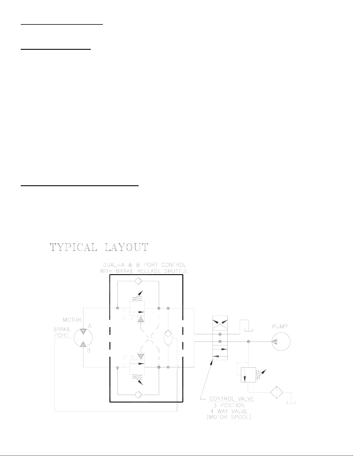
HYDRAULIC SYSTEM REQUIREMENTS
Refer to the performance charts, below, to properly match your hydraulic system to RPH-20000 winch
performance. The charts consist of:
(1) Line pull (lb.) first layer vs. working pressure (PSI) and (2) Line speed, first layer (FPM) vs. gallons per
minute (GPM). Performance based on a motor displacement of 8.0 cubic inches with 15 GPM maximum
flow rate. See page 13 for motor port size.
2 OM-914032-0503-D
Page 5

PERFORMANCE CHARTS
CLUTCH OPERATION
To engage clutch:
BASED ON 8.0 CU. IN/REV. MOTOR
1. Move the clutch control valve to the “clutch engaged” position.
2. Anytime the temperature is below freezing, run the motor in the “cable out” direction only until the
drum starts to turn. In extreme cold temperatures (below 0o F/-18o C), pull out on the cable by
hand only until the drum starts to turn.
3. Wait at least 3 seconds for the clutch to fully engage, after which the winch is ready to winch in
the cable.
WARNING: Do not attempt to engage the clutch by first running the winch motor and then moving
the clutch control valve to the "clutch-engaged" position while the motor is running. Do not start
picking up the load at the same time the clutch is being engaged.
To disengage clutch:
Run the winch in the "cable out" direction until the load is off the cable.
1.
2. Move the clutch control valve to the "clutch-disengaged" position.
The cable may now be pulled off by hand.
WINCH OPERATION
The best way to get acquainted with how your winch operates is to make test runs before you use
it. Plan your test in advance. Remember, you hear your winch, as well as see it operate; learn to
recognize the sounds of a light steady pull, a heavy pull, and sounds caused by load jerking or
shifting. Gain confidence in operating your winch and its use will become second nature with you.
The uneven spooling of cable, while pulling a load, is not a problem, unless there is a cable pileup
on one end of drum. If this happens reverse the winch to relieve the load and move your anchor
point further to the center of the vehicle. After the job is done you can unspool and rewind for a
neat lay of the cable.
3 OM-914032-0503-D
Page 6

MAINTENANCE
Adhering to the following maintenance schedule will keep your winch in top condition and performing
as it should with a minimum of repair.
A. WEEKLY
Check the oil level and maintain it to the oil level plug. If oil is leaking out, determine location and
1.
repair.
2. Check the pressure relief plug in top of the gear housing. Be sure that it is not plugged. Lubricate
cable with light oil.
B. MONTHLY
1. Check the winch mounting bolts. If any are missing, replace them and securely tighten any that are
loose. Use grade 5 or better bolts.
2. Inspect the cable. If the cable has become frayed with broken strands, replace immediately.
C. ANNUALLY
1. Drain the oil from the winch annually or more often if winch is used frequently.
2. Fill the winch to the oil level plug with clean kerosene. Run the winch a few seconds with no load in the
reel in direction. Drain the kerosene from the winch.
3. Refill the winch to the oil level plug with all purpose SAE 80W-140 gear oil.
4. Inspect frame and surrounding structure for cracks or deformation.
TROUBLE SHOOTING GUIDE
--------------------------------------------------------------------------------------------------------------------------------------
CONDITIONS POSSIBLE CAUSE CORRECTION
--------------------------------------------------------------------------------------------------------------------------------------
OIL LEAKS FROM WINCH 1. Seals damaged or worn. 1. Replace seal.
2. Too much oil. 2. Drain excess oil. Refer
to OPERATION.
3. Damaged gaskets. 3. Replace gaskets.
--------------------------------------------------------------------------------------------------------------------------------------
WINCH RUNS TOO SLOW 1. Low flow rate 1. Check flow rate. Refer to
HYDRAULIC SYSTEMS performance
chart page 3.
2. Hydraulic motor worn out. 2. Replace motor.
-------------------------------------------------------------------------------------------------------------------------------------
CABLE DRUM WILL NOT 1. Clutch not disengaged 1. Check air pressure to clutch
FREESPOOL cylinder 90 PSI minimum
required-Refer to page 13.
--------------------------------------------------------------------------------------------------------------------------------------
BRAKE WLL NOT RELEASE 1. Air in hydraulic system 1. Bleed air from brake. Refer to
page 12.
4 OM-914032-0503-D
Page 7

INSTRUCTIONS FOR OVERHAUL
1. Drain oil from gear housing #9 by removing pipe cap #43 from pipe nipple in end bearing.
Remove reducer #41 and relief fitting #35. If new air cylinder is required, remove air cylinder
#30 from cover by removing (4) capscrews #23.
Remove washer #25, nut #26, setscrew #22, and insert #28 from end of air cylinder rod. Apply
Loc-tite to threads of nut #26 and thread onto setscrew #22 to 3/8” from drive end, as shown
below. Apply Loc-tite to threads of setscrew and thread insert #28 over end of setscrew and
against nut. Use setscrew and nut to thread insert #28 into end of air cylinder rod. Tighten nut
against cylinder rod, keeping 3/8” distance from drive end of setscrew to nut. If breather vent is
damaged, remove and replace.
2. Disconnect tube #46 from elbows #29, as shown. Remove motor #37 and gasket #32 by
removing (2) capscrews #20. Remove valve #47, if needed, from motor by loosening (3)
capscrews #19, as shown on page 14.
5 OM-914032-0503-D
Page 8

3. Remove brake assembly (item #31) by removing (2) mounting screws (item #21) attaching brake
to end bearing (item #8). Remove coupling (item #5) and gasket (item #34) from end bearing.
Take note of mounting configuration for proper mounting of parts during re-assembly.
4. Remove winch from upright mounting frame (item #1) by removing (4) capscrews and
lockwashers. Pull motor end bearing (item #8) from drum assembly (item #2).
6 OM-914032-0503-D
Page 9

5. Pull drum assembly (item #2) upward from end bearing (item #9). Remove quad-rings (item #39 &
#38) from grooves in drum bushings. Remove input shaft (item #11), clutch spring (item #45) and
washer (item #27) from end bearing (item #9). Examine splined ends of input shaft for signs of
wear, replace if damaged.
Examine drum assembly (item #2) for signs of wear. If splines inside of drum driver (332166) are
damaged, drum driver must be replaced. Remove drum driver by unscrewing (8) capscrews
(414462). Place well-oiled o-ring (462053) into drum driver groove and attach driver to drum
(332165) using (8) capscrews (414462). Torque capscrews to 55 ft. lbs. each, in criss-cross
pattern.
Press old bushings from drum and drum driver. Remove o-rings (462055 & 462052) from grooves
in drum and drum driver-bushing (412092). Place well-oiled o-rings (462055 & 462052) into
grooves in drum and outer diameter of drum driver bushing (412092). Press new bushing
(412091) into end of drum opposite drum driver and press bushing (412092) into drum driver until
flange of bushings are flush against drum and driver. Secure bushings to drum and drum driver
using (2) capscrews (414819).
7 OM-914032-0503-D
Page 10

6. Remove output coupling (item #7) and coupling shaft (item #6) from end bearing (item #9).
Examine bearings (item #13), pressed in output coupling (item #7), for signs of wear. Replace
bearings, if necessary, by pressing old bearings from coupling and press new bearings (item #13)
into each end of output coupling (item #7). Place coupling shaft (item #6) into bearings (item
#13).
7. Remove (8) capscrews (item #15) to pull gear-housing cover from ring gear. Remove input thrust
washer, sun gear, carrier assemblies, and spacer (item #13) from inside of ring gear. Examine
splines of ring gear and if necessary, remove ring gear from end bearing (item #9) by removing
(12) capscrews (item #16). Examine bushing (item #14) for signs of wear. Replace bushing, if
necessary, by pressing old bushing from housing and pressing new bushing into place.
Apply RTV sealing compound to ring gear-mounting surface of end bearing (item #9). Place ring
gear onto end bearing, aligning holes in ring gear with holes and gear housing end bearing.
Secure ring gear to end bearing using (12) capscrews (item #16). Torque to 44 ft.lbs, each in a
criss-cross pattern. Examine shifter shaft (item #12) for signs of wear, replace if necessary.
8 OM-914032-0503-D
Page 11

9. NOTE: DETERMINE MOUNTING CONFIGURATION OF WINCH (R.H. or L.H. MOUNTED) BEFORE ATTACHING
FRONT AND REAR FRAME ASSEMBLY TO WINCH, TO ASSURE PARTS ARE MOUNTED TO PROPER SIDE,
REFER TO WINCH MOUNTING CONFIGURATIONS, STEP 15 PAGE 12.
Seat well-oiled quad-rings (item #38 & #39) into groove of bushing in each end of drum assembly
(item #2), as shown. Carefully set drum assembly (item #2) down over motor end bearing (item
#9). Lift gear-housing end bearing (item #8) and set into place on drum assembly. Install frame
assembly (item #1) using capscrews and lockwashers shown below. Tighten (4) capscrews
securely, check rotation of cable drum.
10.Liberally apply grease to shoulder of input shaft (item #11). Place spring (item #45) over longer
splined end of shaft. Use grease to hold spring in place against shoulder of shaft.
Place spring and shaft through motor end bearing (item #9) and drum until shaft extends through
bushing (item #14) in end bearing (item #8). Place clutch washer (item #27) over splined end of
shaft and against spring. Place end of output coupling assembly (item #7), with longest spline
inward, through end bearing bushing (item #14) and mesh shaft coupling spline with splined end
of shaft. Place short splined end of shifter shaft (item #12) through washer (item #27) and into
shaft coupling (item #6), meshing splines of shifter shaft with splines in shaft coupling. Place
spacer (item #13) over output coupling assembly (item #7).
9 OM-914032-0503-D
Page 12

11.Place (2) gear carrier assemblies into ring gear meshing carrier gears with ring gear. Make sure
that ring gear and carrier assemblies are securely against end bearing (item #9). Inspect cover oring for damage and replace if necessary. Attach cover to ring gear. Use (8) capscrews (item
#15) to secure gearbox cover to gear housing end bearing. Torque capscrews to 18 ft. lbs. each,
in criss-cross pattern.
12. Pull rod from air cylinder as far as possible. Slide washer (item #33) over setscrew (item #22)
and against nut attached to air cylinder rod. Place setscrew into hole of shifter shaft (item #12).
Attach new air cylinder (item #30) and gasket (item #33) with sealer, to adapter using (4)
capscrews (item #23). Apply Loc-tite PST thread sealer to threads of capscrews. Torque
capscrews to 5 ft. lbs. each, in criss-cross pattern.
10 OM-914032-0503-D
Page 13

13. With pin (item #44) installed in coupling, slide coupling (item #5) over end of input shaft below.
Slide coupling over end of shaft (item #12). Place gasket (Item #34) into position on motor
mounting surface of end bearing (item #8). Insert brake shaft into coupling. Use (2) screws (item
#21) to attach brake assembly to motor end bearing. Torque capscrews to 85 ft lbs each.
14. Attach motor (item #37) with well oiled gasket (item #32) to brake (item #31). Use (2) capscrews
(item #20) and torque to 74 ft. lbs. each. Securely connect tube (item #46) to elbow (item #29), in
valve (item #47), and brake (item #31).
11 OM-914032-0503-D
Page 14

15. Apply Permatex to threads of pipe cap (item #43). Thread pipe cap onto pipe nipple in
bottom of gear housing end bearing (item #9). Pour approx. 1.75 pints of SAE 80W-140 oil into
end bearing. Check oil level by removing oil plug noted below. Insert relief fitting (item #35) and
thread reducer (item #41) into end bearing at oil fill hole.
Install winch and connect pressure lines. Apply at least 230 PSI pressure to release brake and
verify that brake releases, by observing that the winch drum rotates.
12 OM-914032-0503-D
Page 15

13
Page 16

14
RPH 20000
Page 17

15
PARTS LIST – RPH 20000
BEGINNING SERIAL NO. 1000171
ITEM
1 1 242167 ASSY-FRAME 25 12 418218 LOCKWASHER 1/2 MED SECT
2 1 234170 DRUM ASSEMBLY 26 1 418432 WASHER – THRUST
3 1 296504 GEAR BOX 27 1 418433 NUT – 5/16-24 NF X 3/16 THK LOCK
4 1 314010 CABLE ANCHOR 28 2 418462 WASHER – CLUTCH
5 1 324290 COUPLING – BRAKE 29 1 426045 INSERT
6 1 324294 COUPLING – SHAFT 30 2 432018
7 1 324299 COUPLING – OUTPUT 31 1 433014 AIR CYLINDER
8 1 338294 END BEARING – MOTOR 32 1 438020 BRAKE
9 1 338315 END BEARING – GEAR 33 1 442215 GASKET – BRAKE & MOTOR END*
10 2 342194 KEY – RD END 34 1 442217 GASKET – AIR CYLINDER*
11 1 357496 SHAFT – INPUT 35 1 442224 GASKET – BRAKE OUTPUT FACE*
12 1 358073 SHIFTER SHAFT 36 1 456008 RELIEF FITTING
QTY. PART # DESCRIPTION ITEM QTY. PART
NO.
DESCRIPTION
FITTING – HYD 7/16-20 90° ELBOW
13 1 362269 SPACER 37 1 456038 BREATHER VENT
14 2 402119 BEARING 38 1 458081 MOTOR – HYDRAULIC
15 1 412090 BUSHING – THRUST 39 1 462012 QUAD. RING*
16 8 415152 BOLT – M8X1.25X30MM LG. HX HD GR 8.8 Z/P 40 1 462050 QUAD. RING*
17 12 415207 BOLT – M10X1.25X60MM LG. HX HD GR 8.8 41 1 468017 PIPE PLUG
18 10 414561 CAPSCREW ½-13 NC X 1-1/4 LG HX HD GR 5 42 1 468024 REDUCER
19 2 414564 CAPSCREW ½-13 NC X 1-1/2 LG HX HD GR 5 43 1 468036 PIPE NIPPLE
20 3 414935 CAPSCREW 3/8-16NC X 2-1/2 LG HX SOC HD 44 1 468037 PIPE CAP
21 2 414948 CAPSCREW 1/2-13NC X 1-1/4 LG SOC HD 45 1 470091 PIN
22 2 414958 CAPSCREW 1/2-13NC X 4 LG SOC HD 46 1 494108 SPRING
23 1 416051 SETSCREW 5/16-24 NF X 1 LG SOC HD 47 1 509006 TUBE ASSEMBLY
24 4 416234 CAPSCREW #10-24NC X 2-1/4 LG HX SOC HD 48 1 516011 CONTROL VALVE
* THESE ITEMS ARE PART OF SEAL AND GASKET KIT #246047 WHICH ALSO INCLUDES (3) O-RINGS USED IN DRUM ASSEMBLY #234170 (SEE PAGE 7) AND ORING USED ON GEAR BOX COVER (SEE PAGE 10).
Page 18

S
LIMITED WARRANTY
RAMSEY WINCH warrants each new RAMSEY WINCH to be free from defects in
material and workmanship for a period of one (1) year from date of purchase.
The obligation under this warranty, statutory or otherwise, is limited to the
replacement or repair at the Manufacturer's factory, or at a point designated by the
Manufacturer, of such part that shall appear to the Manufacturer, upon inspection of
such part, to have been defective in material or workmanship.
This warranty does not obligate RAMSEY WINCH to bear the cost of labor or
transportation charges in connection with the replacement or repair of defective
parts, nor shall it apply to a product upon which repair or alterations have been
made, unless authorized by Manufacturer, or for equipment misused, neglected or
which has not been installed correctly.
RAMSEY WINCH shall in no event be liable for special or consequential damages.
RAMSEY WINCH makes no warranty in respect to accessories such as being
subject to the warranties of their respective manufacturers.
RAMSEY WINCH, whose policy is one of continuous improvement, reserves the
right to improve its products through changes in design or materials as it may deem
desirable without being obligated to incorporate such changes in products of prior
manufacture.
If field service at the request of the Buyer is rendered and the fault is found not to
be with RAMSEY WINCH's product, the Buyer shall pay the time and expense to
the field representative. Bills for service, labor or other expenses that have been
incurred by the Buyer without approval or authorization by RAMSEY WINCH will not
be accepted.
ee warranty card for details.
RAMSEY WINCH COMPANY
Post Office Box 581510 Tulsa, Oklahoma 74158-1510
Telephone: (918) 438-2760 FAX: (918) 438-6688
OM-914032-0503-D
 Loading...