

Page 1

OPERATING, SERVICE AND
MAINTENANCE MANUAL
Intended Purpose: Vehicle Recovery and Pulling of Loads
CAUTION
AND OPERATION OF WINCH. SEE WARNINGS!
: READ AND UNDERSTAND THIS MANUAL BEFORE INSTALLATION
Page 2

TABLE OF CONTENTS
INTRODUCTION……………………………………………………………………………………………………………….1
WARRANTY INFORMATION………………………………………………………………………………………………...1
SPECIFICATIONS……………………………………………………………………………………………………………..1
WARNINGS…………………………………………………………………………………………………………………….1
WINCH MOUNTING…………………………………………………………………………………………………………...2
CABLE INSTALLATION……………………………………………………………………………………………………….3
HYDRAULIC SYSTEM REQUIREMENTS………………………………………………………………………………….4
PERFORMANCE CHARTS………………………………………………………………………………………………….. 4
OPERATION……………………………………………………………………………………………………………………5
MANUAL CLUTCH SHIFTER………………………………………………………………………………………………...5
AIR CYLINDER CLUTCH SHIFTER………………………………………………………………………………………... 5
MAINTENANCE………………………………………………………………………………………………………………..5
TROUBLE SHOOTING GUIDE………………………………………………………………………………………………6
INSTRUCTIONS FOR OVERHAUL………………………………………………………………………………………….7-11
DIMENSIONAL DRAWINGS
RPH 15,000T WITH MANUAL CLUTCH SHIFTER……………………………………………………………………12
RPH 15,000T WITH AIR CYLINDER CLUTCH SHIFTER…………………………………………………………… 13
PARTS LIST AND PARTS DRAWINGS
RPH 15,000T WITH MANUAL CLUTCH SHIFTER……………………………………………………………………14-15
RPH 15,000T WITH AIR CYLINDER CLUTCH SHIFTER……………………………………………………………. 16-17
LIMITED WARRANTY………………………………………..……………………………………………………………18
Page 3
RAMSEY HYDRAULIC PLANETARY WINCH MODEL RPH-15,000T
PLEASE READ THIS MANUAL CAREFULLY
This manual contains useful ideas in obtaining the most efficient operation from your Ramsey Winch, and safety
procedures one needs to know before operating a Ramsey Winch. Do not operate this winch until you have
carefully read and understand the "WARNING" and "OPERATION" sections of this manual.
WARRANTY INFORMATION
Ramsey Winches are designed and built to exacting specifications. Great care and skill go into every winch we
make. If the need should arise, warranty procedure is outlined on the back of your self-addressed postage paid
warranty card. Please read and fill out the enclosed warranty card and send it to Ramsey Winch Company. If you
have any problems with our winch, please follow instructions for prompt service on all warranty claims. Refer to
back page for limited warranty.
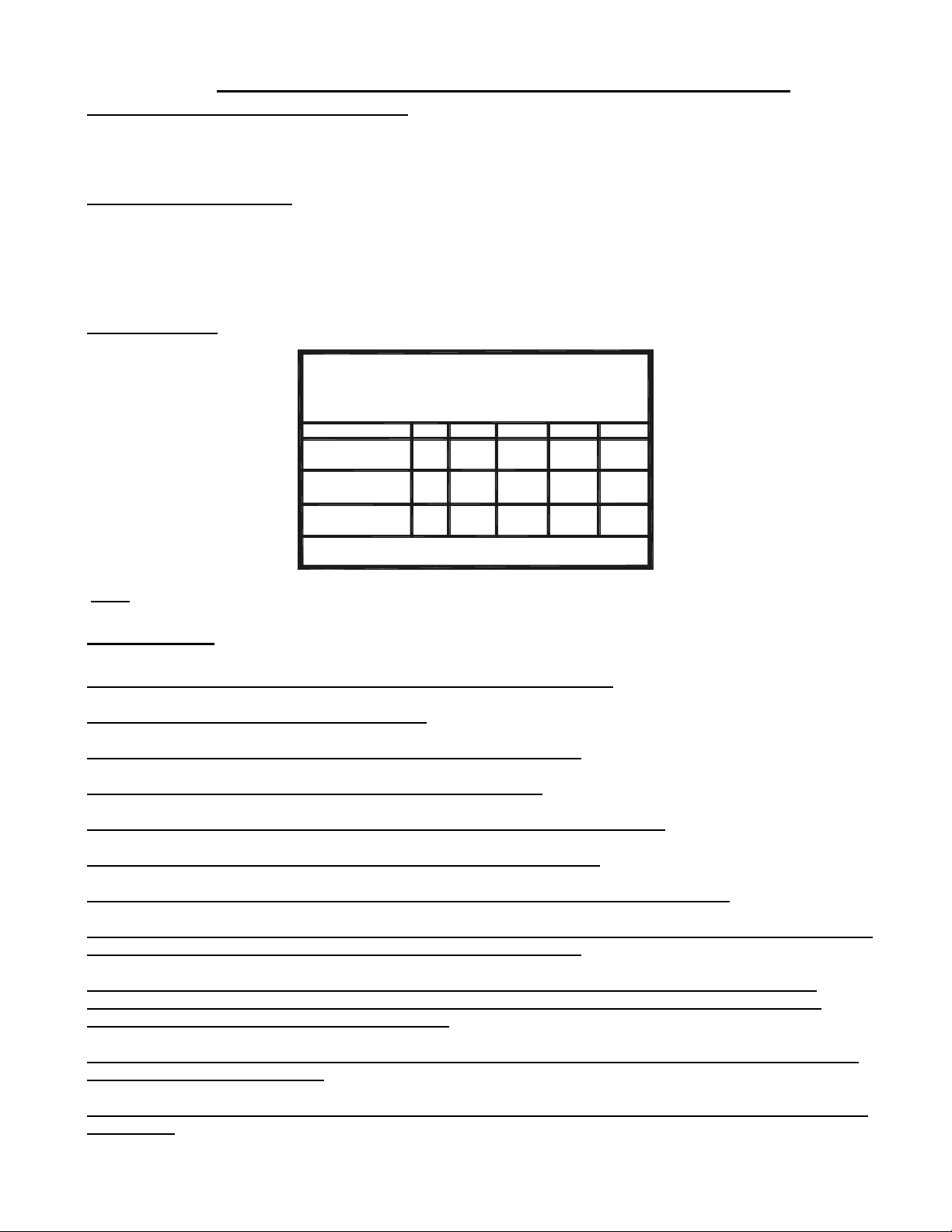
SPECIFICATIONS*
NOISE LEVEL: 74 dB(A)
Rated Line Pull (lbs.).........................................................................15,000
(Kn).............................................................................................. 57
Gear Reduction....................................................................................7.7:1
Weight (without cable)....................................................300 lbs. (136 kgs.)
LAYER OF CABLE 1 2 3 4
*Rated line pull
per layer
Cable capacity
Line speed
(at 15 GPM)
*These specifications are based on recommended 13 mm
wire rope and a 24.9 Cu. In./Rev. motor.
Lbs.
Kn.
Ft.
M.
FPM
MPM
10,88012,810 9,460 8,365
48.4 42.0 37.0
75
22
29
8,8
35
10
7,6
25
57.0
125
38
34
10,3
177
53
39
11,8
NOTE: The rated line pulls shown are for the winch only. Consult the wire rope manufacturer for wire rope ratings.
WARNINGS:
CLUTCH MUST BE FULLY ENGAGED BEFORE STARTING THE WINCH.
DO NOT DISENGAGE CLUTCH UNDER LOAD.
DO NOT LEAVE CLUTCH ENGAGED WHEN WINCH IS NOT IN USE.
STAY OUT FROM UNDER AND AWAY FROM RAISED LOADS.
STAND CLEAR OF CABLE WHILE PULLING. DO NOT TRY TO GUIDE CABLE.
DO NOT EXCEED MAXIMUM LINE PULL RATINGS SHOWN IN TABLE.
DO NOT USE WINCH TO LIFT, SUPPORT, OR OTHERWISE TRANSPORT PERSONNEL.
A MINIMUM OF 5 WRAPS OF CABLE AROUND THE DRUM BARREL IS NECESSARY TO HOLD THE LOAD.
CABLE CLAMP (SETSCREW) IS NOT DESIGNED TO HOLD LOAD.
IN CAR CARRIER APPLICATIONS, AFTER PULLING VEHICLE ON CARRIER, BE SURE TO SECURE
VEHICLE TO CARRIER BED. DO NOT MAINTAIN LOAD ON WINCH CABLE WHILE TRANSPORTING
VEHICLE. DO NOT USE WINCH AS A TIE DOWN.
WHEN PULLING A HEAVY LOAD PLACE A BLANKET, JACKET, OR TARPAULIN OVER THE CABLE FIVE
OR SIX FEET FROM THE HOOK.
AVOID CONDITIONS WHERE LOAD SHIFTS OR JERKS OCCUR, AS THEY MAY INDICATE A DANGEROUS
SITUATION.
1
OM-914020-0199-A
Page 4
WINCH MOUNTING
ESSENTIAL MOUNTING INSTRUCTIONS TO MAINTAIN ALIGNMENT OF PLANETARY WINCH
COMPONENTS
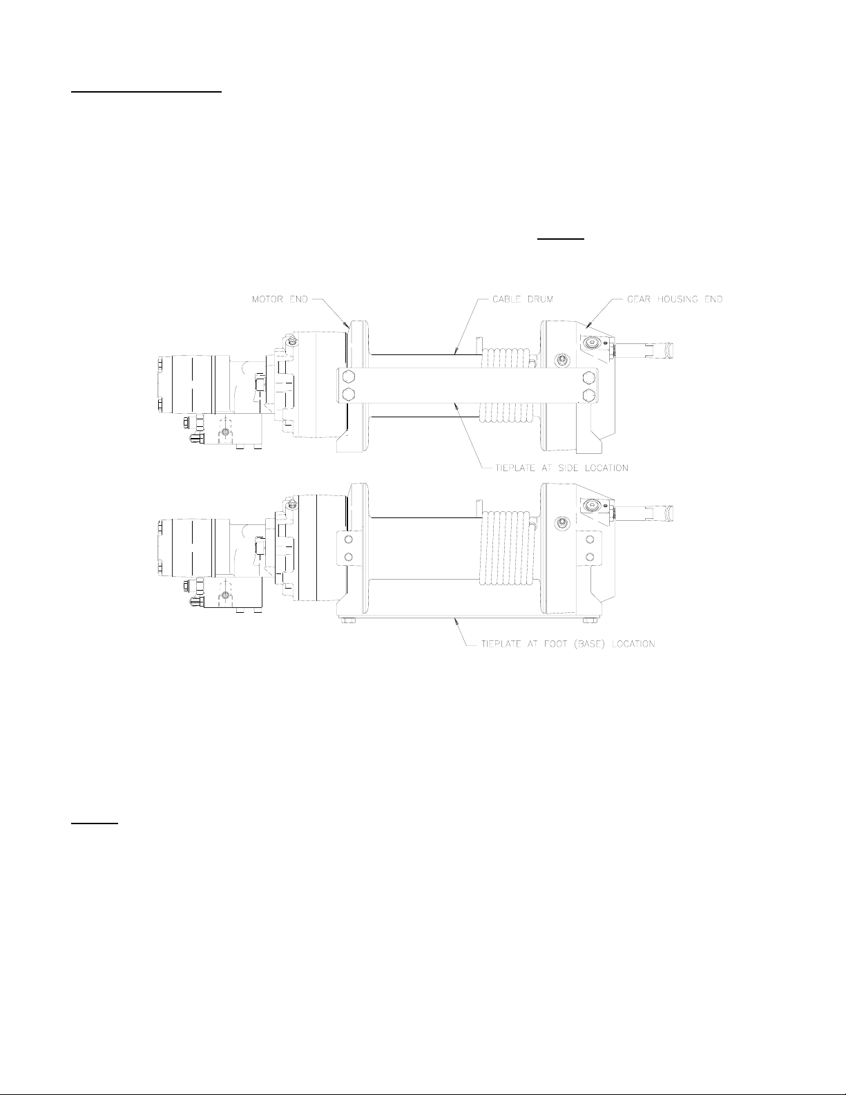
It is most important that this winch be mounted securely so that the three major sections (the motor end,
the cable drum and the gear-housing end) are properly aligned. Excessive bushing wear and difficulty in
freespooling are usually symptoms of misalignment.
In the as-installed condition, if the winch is mid mounted then at least one tie plate must be attached to
the mounting feet at the bottom of the winch to maintain alignment. NOTE:
then at least one tie plate must remain mounted at mid point of winch to maintain alignment. It is
always desirable to use both tie plates in the final installed configuration.
If the winch is foot mounted
Angle Mounting Kit, #251173 is recommended for maximum ease in mounting the winch. The angle kit
will allow the winch to be mounted in upright or midmount applications and will meet the criteria of
serving as a solid and true mounting surface.
When mounting the winch with other than the recommended Ramsey Angle Kit, the mounting hole
patterns described on page 12 must be used. The mounting surface must be flat within .015 inch and
sufficiently stiff to resist flexing. If a steel plate is used for foot mounting it should be .750 inch thick. For
this mounting application eight (8) 5/8-11NC x 1-1/2 Lg. Gr. 5 capscrews with lockwashers will be
needed to mount winch. Capscrews should be torqued to 173 ft. lb. (235 Nm.).
NOTE: If angles or a steel plate are used in mounting winch, tie plates provided with winch are to be
attached to the remaining mounting pads, whether they be side or foot.
2
OM-914020-0199-A
Page 5
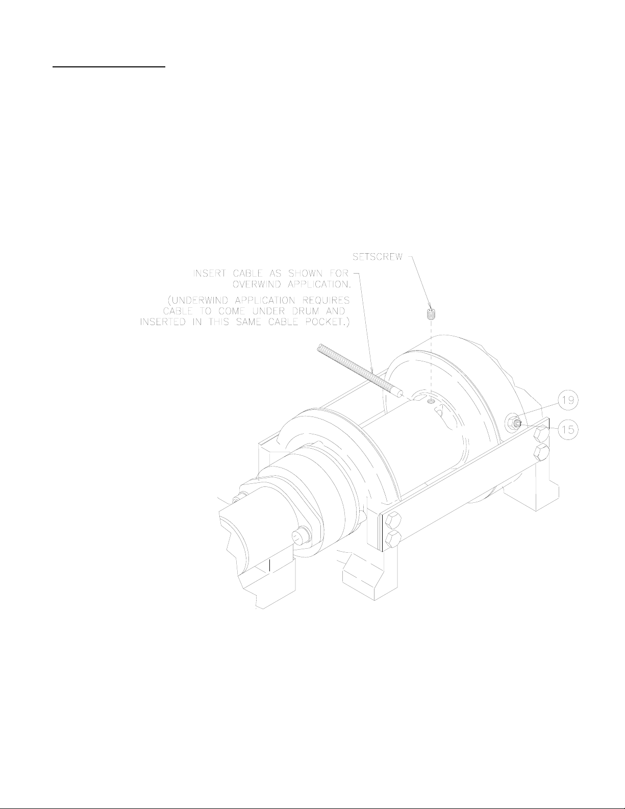
CABLE INSTALLATION
1. Unwind cable by rolling it out along the ground to prevent kinking. Securely wrap end of cable,
opposite hook, with plastic or similar tape to prevent fraying.
2. Place taped end of cable into hole in cable drum, as shown below. Use 3/8-16NC x 1/2 lg. Hex. Soc.
drive setscrew (part of 234173 to secure cable to drum.
3. Carefully run winch in the "reel-in" direction. Keeping tension on end of cable, spool all the cable onto
the cable drum, taking care to form neatly wrapped layers.
After installing cable, check freespool operation. Disengage clutch and pull on cable at a walking speed.
If cable "Birdnests", loosen jam nut (item #19) and turn nylon screw (item #15) clockwise to increase
drag on drum. If cable pull is excessive loosen nylon setscrew by turning counterclockwise. Tighten jam
nut when proper setting is obtained. CAUTION: Over-tightening of jam nut may strip nylon
setscrew.
3
OM-914020-0199-A
Page 6
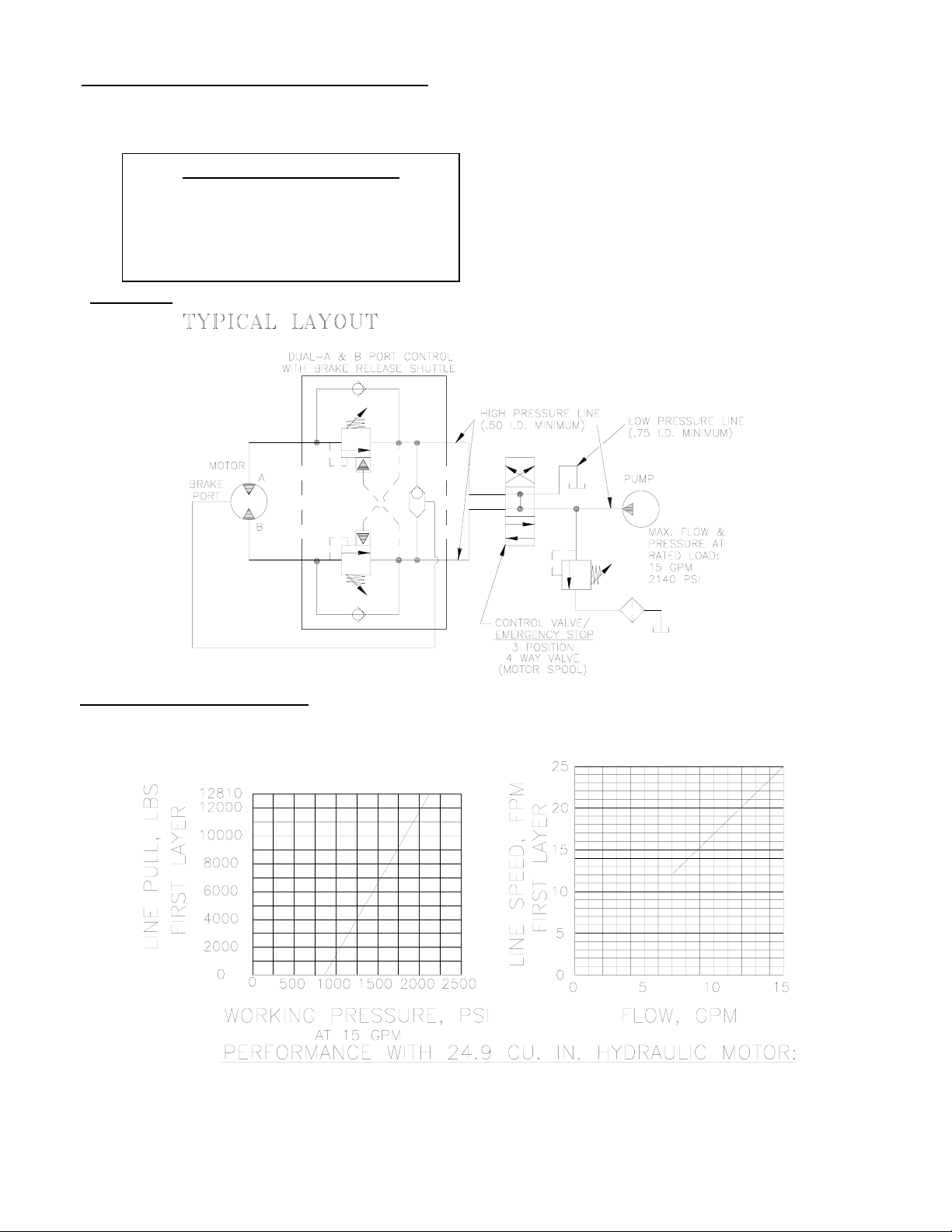
HYDRAULIC SYSTEM REQUIREMENTS
Refer to the performance charts below to properly match your hydraulic system to the winch performance. The
charts consist of: (1) line pull (LB) first layer vs. working pressure (PSI) and (2) line speed, first layer (FPM) vs.
flow (GPM). A motor spool directional control valve is recommended.
INSTALLER MUST DETERMINE TYPE OF
EMERGENCY STOP REQUIRED. A MANUAL
CONTROL VALVE ALSO SERVES AS AN
EMERGENCY STOP VALVE. AN EMERGENCY
STOP VALVE MAY BE REQUIRED WITH OTHER
SYSTEM REQUIREMENTS:
2140 PSI RELIEF VALVE SETTING
15 GPM FLOW RATE*
10 MICRON NOMINAL FILTRATION
1000 PSI MAXIMUM BACK PRESSURE
EMERGENCY STOP VALVE
TYPES OF CONTROL VALVES.
*CAUTION: DO NOT EXCEED 20 GPM. IF EXCEEDED, MOTOR AND WINCH MAY BE DAMAGED.
PERFORMANCE CHARTS
4
OM-914020-0199-A
Page 7

OPERATION
The best way to get acquainted with how your winch operates is to make test runs before you actually use it. Plan
your test in advance. Remember that you hear your winch, as well as see it operate. Get to recognize the sounds
of a light steady pull, a heavy pull, and sounds caused by load jerking or shifting. Avoid conditions where load shifts
or jerks occur, as they may indicate a dangerous situation.
The uneven spooling of cable, while pulling a load, is not a problem, unless there is a cable pileup on one end of
drum. If this happens, reverse the winch to relieve the load and move your anchor point further to the center of the
vehicle. After the job is done you can unspool and rewind for a neat lay of the cable.
When pulling a heavy load, place a blanket, jacket or tarpaulin over the cable about five or six feet behind the hook.
In the event of a broken cable, this will slow the snap back of the cable and could prevent serious injury.
The winch clutch allows rapid unspooling of the cable, from cable drum, for hooking onto the load. The clutch is
operated by the clutch shifter lever or air shifter.
WARNING:
DO NOT DISENGAGE CLUTCH UNDER LOAD.
MANUAL CLUTCH SHIFTER (Refer to page 12)
TO DISENGAGE CLUTCH: Run the winch in the reverse (reel out) direction until load is off the cable. Pull handle
out and rotate 90o. With handle in the "DISENGAGED" position cable may now be free-spooled from drum.
TO ENGAGE CLUTCH: Pull handle out, rotate 90o and release handle. Run the winch in reverse until the clutch
handle snaps fully into the "ENGAGED" position. DO NOT attempt to pull a load unless the handle is fully at the
"ENGAGED" position. If manual shift indicator light is present, the green light is lit when clutch is fully "ENGAGED".
DO NOT attempt to pull a load unless the green light is lit. To hookup light to the vehicle electrical system refer to
the Electrical Schematic on page 13.
AIR CYLINDER CLUTCH SHIFTER (Refer to page 13)
TO DISENGAGE CLUTCH: Run the winch in the reverse (reel out) direction until load is off the cable. Apply air
pressure to the .125-27 NPT port: 80 PSI (min.), 150 PSI (max.). CAUTION:
TO ENGAGE CLUTCH: Remove air pressure from the cylinder (a return spring engages the plunger). Run winch in
reverse until the clutch engagement indicator light (green light) is lit. DO NOT attempt to pull a load unless the
green light is lit. To hookup light to the vehicle electrical system refer to the Electrical Schematic on page 13.
MAINTENANCE
1. Inspect the cable for damage and lubricate frequently. If the cable becomes frayed with broken strands, replace
immediately.
2. Check that the clutch is fully engaging. See OPERATION instructions, above for the appropriate clutch shifter.
FOR MANUAL CLUTCH ONLY: Monthly disengage clutch, put several drops of oil on the shaft and work clutch
IN and OUT several times to lubricate inside of clutch cylinder
Pressure must not exceed 150 PSI.
3. Check to see that drum cable does not overrun (BIRDNEST) when freespooling. Refer to page 3.
4. Replace drum bushings and seals when seals begin to seep grease. Refer to OVERHAUL INSTRUCTIONS,
page 8. Add additional lubricant, Mobilith SHC 007, to gears if required.
5
OM-914020-0199-A
Page 8

TROUBLE SHOOTING GUIDE
CONDITIONS POSSIBLE CAUSE CORRECTION ____ _
DRUM WILL NOT ROTATE Winch not mounted squarely, Check mounting. Refer to
AT NO LOAD causing end bearings to bind up drum. WINCH MOUNTING page 2.
Brake damaged. Inspect and replace brake.
Gears damaged. Inspect and replace damaged gears.
------------------------------------------------------------------------------------------------------------------------------------------------------------------DRUM WILL NOT ROTATE Load greater than rated Refer to Specifications pg.1
UNDER LOAD capacity of winch. for line pull rating.
Low hydraulic system Check pressure. Refer to HYDRAULIC
pressure. SYSTEMS performance charts pg. 4.
Winch not mounted squarely, Check mounting. Refer to
causing end bearing to bind WINCH MOUNTING pg. 2.
up drum.
------------------------------------------------------------------------------------------------------------------------------------------------------------------WINCH RUNS TOO SLOW Low hydraulic system flow rate. Check flow rate. Refer to
HYDRAULIC SYSTEMS flow chart page 4.
Motor worn out. Replace motor.
------------------------------------------------------------------------------------------------------------------------------------------------------------------DRUM WILL NOT Clutch not disengaged. Check OPERATION. Refer to page 5.
FREESPOOL Check ADJUSTMENT. Refer to page 10.
Winch not mounted squarely, Check mounting. Refer to WINCH
causing end bearings to bind drum. MOUNTING pg. 2
------------------------------------------------------------------------------------------------------------------------------------------------------------------BRAKE WILL NOT RELEASE Air in hydraulic system Bleed air from brake. Refer to page 11.
------------------------------------------------------------------------------------------------------------------------------------------------------------------CABLE BIRDNESTS WHEN Drag screw improperly Adjust nylon drag screw.
CLUTCH IS DISENGAGED adjusted. Refer to pg. 3.
------------------------------------------------------------------------------------------------------------------------------------------------------------------EXCESSIVE NOISE Hydraulic system flow too high Check flow rate. Refer to HYDRAULIC
SYSTEMS flow chart pg. 4.
Drum in bind, winch not Check mounting. Refer to
mounted squarely. WINCH MOUNTING pg. 2
------------------------------------------------------------------------------------------------------------------------------------------------------------------DRUM CHATTERS, Low hydraulic system flow. Check flow rate. Refer to HYDRAULIC
in "REEL IN" direction SYSTEMS flow chart pg. 4.
Low hydraulic system Check relief valve setting. Refer to
relief pressure setting. HYDRAULIC SYSTEMS pg. 4.
------------------------------------------------------------------------------------------------------------------------------------------------------------------BRAKE WILL NOT RELEASE Air in hydraulic system Bleed air from brake. Refer to page 11.
-------------------------------------------------------------------------------------------------------------------------------------------------------------------
6
OM-914020-0199-A
Page 9

INSTRUCTIONS FOR OVERHAUL OF RAMSEY WINCH
MODEL RPH 15,000T
DISASSEMBLY
Take note of mounting configuration for proper mounting of parts during re-assembly.
Disconnect tube (item #29) from elbows on bottom of brake (item #22) and valve (item #30).
Remove motor (item #24) from brake (item #22) by unscrewing capscrews (item #17). Tap
motor lightly to disengage.
Remove brake assembly screws from brake (item #22) to access (2) mounting screws (item
#16) attaching brake to end bearing (item #6). Remove coupling (item #3) and gasket (item
#23) from end bearing. If coupling is being replaced, be sure pin (item #26) is removed from
old coupling and installed into new coupling. If necessary, remove valve (item #31) from
motor by removing capscrews (item #14). If valve is removed, make sure two square cross
section o-rings remain seated in their counter bores in valve.
7
OM-914020-0199-A
Page 10

Remove tie plates (item #9) from end bearings (items #5 & #6) by unscrewing capscrews
(item #13), as shown. Slide motor end bearing (item #6) from drum (item #1) and drum from
gear housing end bearing (item #5). Remove input shaft (item #8) and thrust washers (items
#32, #33 & #34 ) from end bearings. Inspect gear teeth of shaft (item #8) and key (item #7)
for signs of wear. If necessary replace shaft and/or key.
8
OM-914020-0199-A
Page 11

Remove o-ring (item #25) from motor end bearing (item #6). Dip new o-ring in oil and seat
into groove of end bearing.
Remove seal (item #29) from gear housing end bearing (item #5). Loosen nut (item #19) and
remove nylon setscrew (item #15) and remove ring gear (item #4) from gear housing end
bearing. Install ring gear and nylon setscrew and nut. Ring gear must be fully seated in gear
housing end bearing (item #5) and slot in ring gear must be aligned with clutch shifter hole.
Dip new seal in oil and install in gear housing end bearing, with sharp edge of seal outward.
9
OM-914020-0199-A
Page 12

Generously apply grease (MOBILITH SHC 007) to teeth of ring gear (item #4), teeth of planet gears in drum (item
#1) and to bushing in end bearing (item #5). Apply grease to teeth of gear and short end of shaft (item #8).
Place gear end of shaft through backside of drum (item #1) rotate shaft to mesh shaft gear with planet gear in
drum. Apply grease to end of shaft and to I.D. and O.D. of bushing protruding from drum. Place thrust washer
(item #32) over end of shaft and against gear teeth of shaft. Set thrust washer (item #34) over bushing and
against drum. Place drum assembly into end bearing meshing planet gears with output gear on shaft and with
ring gear in end bearing. End of drum shaft is placed into bearing pressed in end bearing (item #5).
Apply grease to and O.D. of bushing protruding from drum. Set thrust washer (item #33) over bushing and
against drum. Assemble motor end bearing (item #6) to drum assembly and use tie plates (item #9) and
capscrews (item #13) to hold both end bearings together. Tighten capscrews to 173 Ft. Lbs. (235 Nm.). If
necessary, remove and replace appropriate shifter assembly (item #2 or #3), as follows:
MANUAL CLUTCH SHIFTER ASSEMBLY
Remove by loosening setscrew (item #18), jam nut and unscrewing clutch shifter. Be sure slot in ring gear is not
aligned with clutch shifter hole in end bearing. Rotate drum, if necessary, to insure hole and slot are not aligned.
Reinstall clutch shifter with plunger, jam nut and handle positioned in cylinder housing, as shown. Thread
assembly (with handle engaged in cylinder slot) into the end bearing. Pull drum toward the gear housing end
bearing to remove play. Hold drum in this position and continue threading the shifter assembly in until the gap
between the end of the handle and cylinder is 7/16
shown below. NOTE: This gap will vary with drum endplay. With the drum pulled against the gear housing, the
gap should be 3/8 inch. Lightly tighten jam nut. Rotate drum until handle snaps fully into the engaged position.
Pull handle out and rotate 90o. Verify that drum can be rotated freely (at least one full revolution) with clutch
shifter at DISENGAGED position. Securely tighten jam nut while holding the handle. Tighten setscrew securely.
Re-check clutch operation as described on page 5.
AIR CYLINDER SHIFTER ASSEMBLY
Remove by loosening setscrew (item #18), jam nut and unscrewing clutch shifter. To reinstall, thread air cylinder
into housing. Install one or two shims (item #34) under cylinder head, if needed, to orient air cylinder port for
pneumatic connections. Tighten setscrew. Refer to page 5 and check for proper operation of the clutch.
+0
inch and handle is in the horizontal position, as
-1/16
10
OM-914020-0199-A
Page 13

With pin (item #26) installed in coupling, align keyway of coupling (item #3) with key and end of input shaft below.
Slide coupling over end of shaft (item #8). Place gasket (Item #23) into position on motor mounting surface of end
bearing (item #6). Insert brake shaft (with key) into coupling. Use (2) screws (item #16) to attach brake
cover/shaft assembly to motor end bearing. Torque capscrews to 85 ft lbs each. Re-attach brake module
assembly to brake cover/shaft assembly using brake module assembly screws. Torque capscrews to 85 ft. lbs.
each.
NOTE: Care must be taken to assure cover and brake module are seated properly prior to installing 1/2-13UNC
assembly bolts. Damage will occur to rotor stack or shaft snap ring if not properly seated.
11
OM-914020-0199-A
Page 14

Attach motor (item #24) to brake (item #22). Use (2) capscrews (item #17) with lockwashers (item #20) and torque
to 74 ft. lbs. each. Securely connect tube (item #29) to elbows (item #21) in bottom of valve (item #30) and in
bottom of brake (item #22).
Bleed pressure release section of brake by loosening bleeder fitting on brake and allowing air to escape while
slowly appling hydraulic system pressure to the winch. Apply at least 230 PSI pressure to release brake and verify
that brake releases, by observing that the winch drum rotates.
12
OM-914020-0199-A
Page 15

13
OM-914020-0199-A
Page 16

14
OM-914020-0199-A
Page 17

PARTS LIST RPH 15,000T WITH MANUAL CLUTCH SHIFTER
ITEM QTY. PART NO. DESCRIPTION
1 1 234173 DRUM ASS'Y.
2 1 276052 SHIFTER ASS'Y.-MANUAL
3 1 324287 COUPLING-BRAKE
4 1 334177 GEAR-RING
5 1 338297 HOUSING-GEAR, END BEARING
6 1 338298 END BEARING-MOTOR
7 2 342081 KEY
8 1 357503 SHAFT-INPUT
9 2 395236 TIE PLATE
10 1 402120 BEARING
11 1 412095 BUSHING-DRUM (MTR. END)
12 1 412096 BUSHING-DRUM (G.HSG. END)
13 8 414664 CAPSCREW-5/8-11NC X 1 LG. HX. HD., GR. 5
14 4 415153 SCREW-M8-1.25 X 60MM LG., HX. SOC. HD.
15 1 414926 SETSCREW-3/8-16NC X 1 LG., SOCKET, NYLON
16 2 414947 CAPSCREW-1/2-13NC X 1 LG., SOC. HD.
17 2 414952 CAPSCREW-1/2-13NC X 1-1/2 LG., SOC. HD. PLTD.
18 1 416016 SETSCREW-1/4-20NC X 1/4 LG., HX. SOC. HD.
19 1 418036 NUT 3/8-16NC HEX. JAM
20 2 418218 LOCKWASHER-1/2 ID MED. SECT.
21 2 432018 FITTING-7/16 ELBOW
22 1 438021 BRAKE-"A" MOUNT
23 2 442215 GASKET
24 1 458088 MOTOR-HYDRAULIC
25 1 462061 O-RING (DRUM)
26 1 470089 ROLL PIN
27 1 472052 PLUG
28 1 486081 SEAL-GEAR HSG.
29 1 509008 TUBE ASSEMBLY
30 1 516012 VALVE-MOTOR CONTROL
31 1 518037 THRUST WASHER
32 1 518047 THRUST WASHER
33 1 518053 THRUST WASHER (MTR. END) 3.03 I.D. X 3.75 O.D. X .256 TK.
34 1 518054 THRUST WASHER (G. H. END) 2.76 I.D. X 3.87 O.D. X .250 TK.
15
OM-914020-0199-A
Page 18

16
OM-914020-0199-A
Page 19

PARTS LIST RPH 15,000T WITH AIR-CYLINDER CLUTCH SHIFTER
ITEM QTY. PART NO. DESCRIPTION
1 1 234173 DRUM ASS'Y.
2 1 236020 LIGHT ASS'Y.
3 1 276053 SHIFTER ASS'Y.-AIR
4 1 312526 BRACKET-LIGHT MTG.
5 1 324287 COUPLING-BRAKE
6 1 334177 GEAR-RING
7 1 338297 HOUSING-GEAR, END BEARING
8 1 338298 END BEARING-MOTOR
9 2 342081 KEY
10 1 357503 SHAFT-INPUT
11 2 395236 TIE PLATE
12 1 402120 BEARING
13 1 412095 BUSHING-DRUM (MTR. END)
14 1 412096 BUSHING-DRUM (G.HSG. END)
15 2 414036 CAPSCREW-1/4-20NC X 1/2, HX. HD., GR. 5, F/B
16 8 414664 CAPSCREW-5/8-11NC X 1 LG. HX. HD., GR. 5
17 4 415153 SCREW-M8-1.25 X 60MM LG., HX. SOC. HD.
18 1 414926 SETSCREW-3/8-16NC X 1, SOCKET, NYLON
19 2 414947 CAPSCREW-1/2-13NC X 1, SOC. HD.
20 2 414952 CAPSCREW-1/2-13NC X 1-1/2 LG., SOC. HD. PLTD.
21 1 416016 SETSCREW-1/4-20NC X 1/4 HX. SOC. HD.
22 1 418036 NUT 3/8-16NC HEX. JAM
23 2 418218 LOCKWASHER-1/2 ID MED. SECT.
24 2 432018 FITTING-7/16 ELBOW
25 1 438021 BRAKE-"A" MOUNT
26 2 442215 GASKET
27 1 458088 MOTOR-HYDRAULIC
28 1 462061 O-RING (DRUM)
29 1 470089 ROLL PIN
30 1 482013 GROMMET
31 1 482045 RUBBER BOOT
32 1 486081 SEAL-GEAR HSG.
33 2 488007 SHIM
34 1 504021 SWITCH ASS'Y.
35 1 509008 TUBE ASSEMBLY
36 1 516012 VALVE-MOTOR CONTROL
37 1 518047 THRUST WASHER
38 1 518053 THRUST WASHER (MTR. END) 3.03 I.D. X 3.75 O.D. X .256 TK.
39 1 518054 THRUST WASHER (G. H. END) 2.76 I.D. X 3.87 O.D. X .250 TK.
17
OM-914020-0199-A
Page 20

18
OM-914020-0199-A
Page 21

19
Page 22

RAMSEY WINCH warrants each new RAMSEY Winch to be free from defects in material and workmanship
for a period of one (1) year from date of purchase.
The obligation under this warranty, statutory or otherwise, is limited to the replacement or repair at the
Manufacturer's factory, or at a point designated by the Manufacturer, of such part that shall appear to the
Manufacturer, upon inspection of such part, to have been defective in material or workmanship.
This warranty does not obligate RAMSEY WINCH to bear the cost of labor or transportation charges in
connection with the replacement or repair of defective parts, nor shall it apply to a product upon which
repair or alterations have been made, unless authorized by Manufacturer, or for equipment misused,
neglected or which has not been installed correctly.
LIMITED WARRANTY
RAMSEY WINCH shall in no event be liable for special or consequential damages. RAMSEY WINCH
makes no warranty in respect to accessories such as being subject to the warranties of their respective
manufacturers.
RAMSEY WINCH, whose policy is one of continuous improvement, reserves the right to improve its
products through changes in design or materials as it may deem desirable without being obligated to
incorporate such changes in products of prior manufacture.
If field service at the request of the Buyer is rendered and the fault is found not to be with RAMSEY
WINCH's product, the Buyer shall pay the time and expense to the field representative. Bills for service,
labor or other expenses that have been incurred by the Buyer without approval or authorization by
RAMSEY WINCH will not be accepted
RAMSEY WINCH COMPANY
Post Office Box 581510 Tulsa, Oklahoma 74158-1510
Telephone: (918) 438-2760 FAX: (918) 438-6688
OM-914020-0199-A
 Loading...