

Page 1
OPERATING, SERVICE AND
MAINTENANCE MANUAL
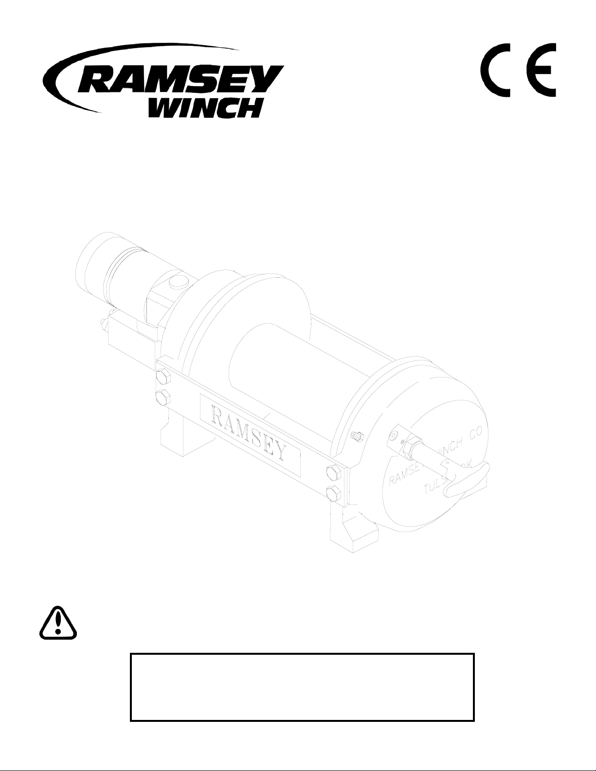
MODEL RPH-15000 PLANETARY WINCH
CAUTION: READ AND UNDERSTAND THIS MANUAL BEFORE INSTALLATION AND
OPERATION OF WINCH. SEE WARNINGS!
English . . . . . . . . . . . . . . . . . . . . .1
Français . . . . . . . . . . . . . . . . . . .17
Deutsch . . . . . . . . . . . . . . . . . . .33
Español . . . . . . . . . . . . . . . . . . .49
Ramsey Winch Company
P.O. Box 581510 - Tulsa, OK 74158-1510 USA
Phone: (918) 438-2760 - Fax (918) 438-6688
Visit us at http://www.ramsey.com
OM-914197-0309-C
Page 2

TABLE OF CONTENTS
I
NTRODUCTIONS . . . . . . . . . . . . . . . . . . . . . . . . . . . . . . . . . . . . . . . . . . . . . . . . . . . . . . . . . . . . . . . . . . . . . . .3
WARRANTY INFORMATION . . . . . . . . . . . . . . . . . . . . . . . . . . . . . . . . . . . . . . . . . . . . . . . . . . . . . . . . . . . . . . .3
SPECIFICATIONS . . . . . . . . . . . . . . . . . . . . . . . . . . . . . . . . . . . . . . . . . . . . . . . . . . . . . . . . . . . . . . . . . . . . . . .3
WARNINGS . . . . . . . . . . . . . . . . . . . . . . . . . . . . . . . . . . . . . . . . . . . . . . . . . . . . . . . . . . . . . . . . . . . . . . . . . . .3
WINCH MOUNTING . . . . . . . . . . . . . . . . . . . . . . . . . . . . . . . . . . . . . . . . . . . . . . . . . . . . . . . . . . . . . . . . . . . . .4
CABLE INSTALLATION . . . . . . . . . . . . . . . . . . . . . . . . . . . . . . . . . . . . . . . . . . . . . . . . . . . . . . . . . . . . . . . . . . .4
MAINTENANCE . . . . . . . . . . . . . . . . . . . . . . . . . . . . . . . . . . . . . . . . . . . . . . . . . . . . . . . . . . . . . . . . . . . . . . . .5
OPERATION . . . . . . . . . . . . . . . . . . . . . . . . . . . . . . . . . . . . . . . . . . . . . . . . . . . . . . . . . . . . . . . . . . . . . . . . . . .5
HYDRAULIC SYSTEM REQUIREMENTS . . . . . . . . . . . . . . . . . . . . . . . . . . . . . . . . . . . . . . . . . . . . . . . . . . . . . .6
TYPICAL LAYOUT . . . . . . . . . . . . . . . . . . . . . . . . . . . . . . . . . . . . . . . . . . . . . . . . . . . . . . . . . . . . . . . . . . . . . .6
PERFORMANCE CHARTS . . . . . . . . . . . . . . . . . . . . . . . . . . . . . . . . . . . . . . . . . . . . . . . . . . . . . . . . . . . . . . . . .6
TROUBLE SHOOTING GUIDE . . . . . . . . . . . . . . . . . . . . . . . . . . . . . . . . . . . . . . . . . . . . . . . . . . . . . . . . . . . . . .7
OVERHAUL INSTRUCTIONS . . . . . . . . . . . . . . . . . . . . . . . . . . . . . . . . . . . . . . . . . . . . . . . . . . . . . . . . . . . .8-10
DIMENSIONAL DRAWINGS . . . . . . . . . . . . . . . . . . . . . . . . . . . . . . . . . . . . . . . . . . . . . . . . . . . . . . . . . . . .11-12
PARTS LIST AND PARTS DRAWINGS . . . . . . . . . . . . . . . . . . . . . . . . . . . . . . . . . . . . . . . . . . . . . . . . . . . .13-16
LIMITED WARRANTY
RAMSEY WINCH warrants each new RAMSEY Winch to be free from defects in material and workmanship for a period of one (1) year
from date of purchase.
The obligation under this warranty, statutory or otherwise, is limited to the replacement or repair at the Manufacturer's factory, or at a point
designated by the Manufacturer, of such part that shall appear to the Manufacturer, upon inspection of such part, to have been defective in
material or workmanship.
This warranty does not obligate RAMSEY WINCH to bear the cost of labor or transportation charges in connection with the replacement or
repair of defective parts, nor shall it apply to a product upon which repair or alterations have been made, unless authorized by
Manufacturer, or for equipment misused, neglected or which has not been installed correctly.
RAMSEY WINCH shall in no event be liable for special or consequential damages. RAMSEY WINCH makes no warranty in respect to
accessories such as being subject to the warranties of their respective manufacturers.
RAMSEY WINCH, whose policy is one of continuous improvement, reserves the right to improve its products through changes in design or
materials, as it may deem desirable without being obligated to incorporate such changes in products of prior manufacture.
If field service at the request of the Buyer is rendered and the fault is found not to be with RAMSEY WINCH's product, the Buyer shall pay
the time and expense to the field representative. Bills for service, labor or other expenses that have been incurred by the Buyer without
approval or authorization by RAMSEY WINCH will not be accepted.
See warranty card for details.
Page 3
PLEASE READ THIS MANUAL CAREFULLY
This manual contains useful ideas for obtaining the most efficient operation from your Ramsey Winch, and safety procedures
one needs to know before operating a Ramsey Winch. Do not operate this winch until you have carefully read and understand
the "WARNING" and "OPERATION" sections of this manual.
WARRANTY INFORMATION
Ramsey Winches are designed and built to exacting specifications. Great care and skill go into every winch we make. If the
need should arise, warranty procedure is outlined on the back of your self-addressed postage paid warranty card. Please read
and fill out the enclosed warranty card and send it to Ramsey Winch Company. If you have any problems with your winch,
please follow instructions for prompt service on all warranty claims. Refer to back page for limited warranty.
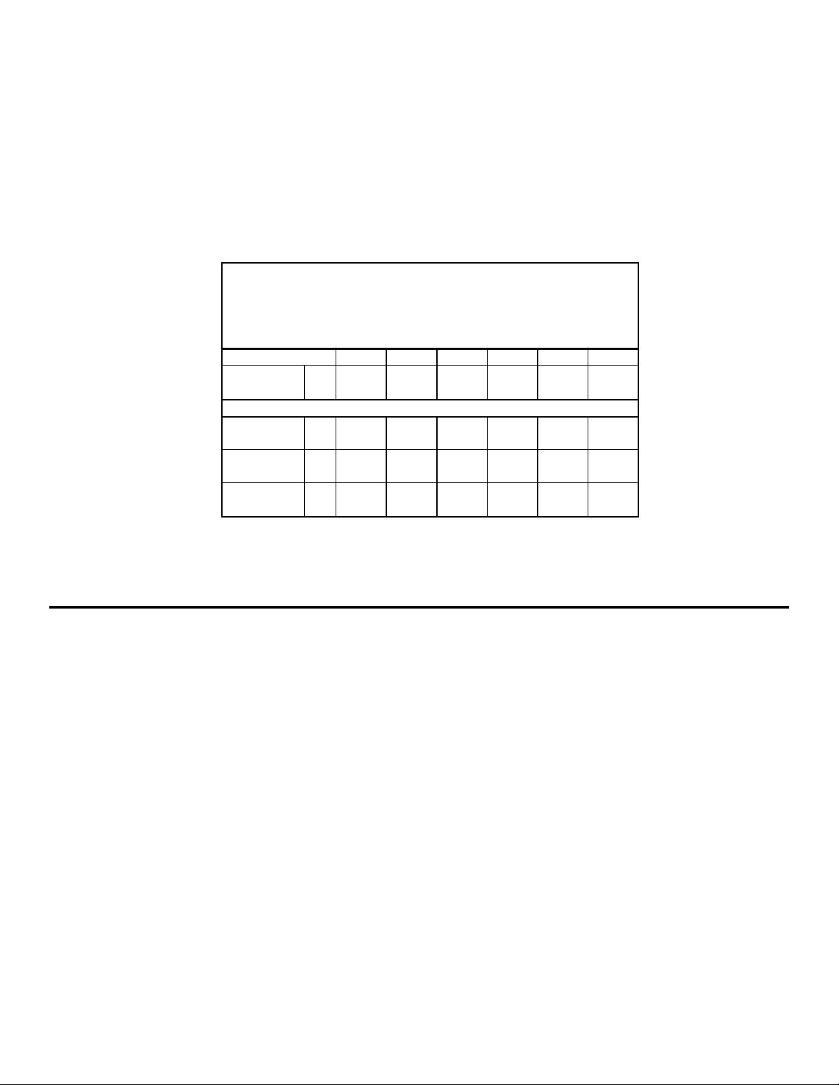
SPECIFICATIONS*
NOTE: The rated line pulls shown are for the winch only. Consult the wire rope manufacturer for wire rope ratings.
WARNINGS:
CLUTCH MUST BE FULLY ENGAGED BEFORE STARTING THE WINCH.
DO NOT DISENGAGE CLUTCH UNDER LOAD.
DO NOT LEAVE CLUTCH ENGAGED WHEN WINCH IS NOT IN USE.
STAY OUT FROM UNDER AND AWAY FROM RAISED LOADS.
STAND CLEAR OF CABLE WHILE PULLING. DO NOT TRY TO GUIDE CABLE.
DO NOT EXCEED MAXIMUM LINE PULL RATINGS SHOWN IN TABLE.
DO NOT USE WINCH TO LIFT, SUPPORT, OR OTHERWISE TRANSPORT PERSONNEL.
A MINIMUM OF 5 WRAPS OF CABLE AROUND THE DRUM BARREL IS NECESSARY TO HOLD THE LOAD. CABLE CLAMP
(SETSCREW) IS NOT DESIGNED TO HOLD LOAD.
IN CAR CARRIER APPLICATIONS, AFTER PULLING VEHICLE ON CARRIER, BE SURE TO SECURE VEHICLE TO CARRIER
BED. DO NOT MAINTAIN LOAD ON WINCH CABLE WHILE TRANSPORTING VEHICLE. DO NOT USE WINCH AS A TIEDOWN.
WHEN PULLING A HEAVY LOAD PLACE A BLANKET, JACKET, OR TARPAULIN OVER THE CABLE FIVE OR SIX FEET FROM
THE HOOK.
AVOID CONDITIONS WHERE LOAD SHIFTS OR JERKS OCCUR, AS THEY MAY INDICATE A DANGEROUS SITUATION.
3
Rated Line Pull (lbs.)
…………………………………………………………………
15,000
(Kg.) …………………………………………………………….. 6,800
Gear Reduction 7.7:1
STD. Drum ……..…....………. 300 lbs. (136 Kg)
"Y" Drum ………….………….. 290 lbs. (131 Kg)
123456**
lbs. 15,000 12,600 10,800 9,500 8,500 7,600
Kg. 6,800 5,710 4,890 4,300 3,850 3,440
ft. 35 75 125 180 240 310
m 102238547394
ft. 20 45 75 110 150 195
m 6 13 22 33 45 60
FPM252934394448
MPM 7,6 8,8 10,3 11,8 13,4 14,6
"Y" DRUM
* These specifications are based on recommended wire rope of 1/2" (13 mm) EIPS cable
and a 24.0 cu.in./Rev. motor.
* Cable Capacity per Layer
** Last layer does not comply with SAE J-706.
……………………………………………………………
Weight (without cable)
LAYER OF CABLE
*Rated line pull
per layer
STD. DRUM
* Line Speed (at
15 GPM)
Page 4
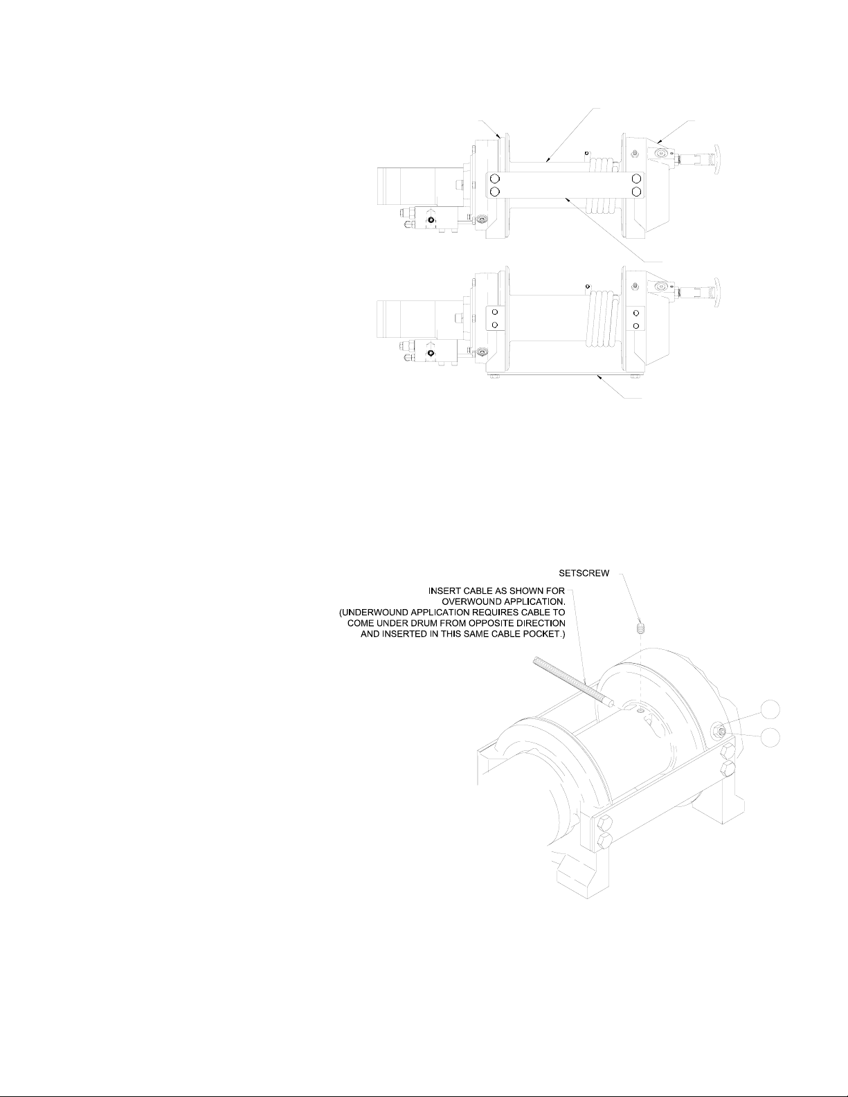
WINCH MOUNTING
ESSENTIAL MOUNTING INSTRUCTIONS TO MAINTAIN ALIGNMENT OF PLANETARY WINCH COMPONENTS:
I
t is most important that this winch be mounted
securely so that the three major sections (the motor
end, the cable drum, and the gear housing end) are
properly aligned. Excessive bushing wear and difficulty
in freespooling are usually symptoms of misalignment.
In the as-installed condition, if the winch is midmounted, then at least one tie-plate must be attached
to the mounting feet at the bottom of the winch to
maintain alignment. If the winch is foot mounted then
at least one tie-plate must remain mounted at midpoint
of winch to maintain alignment. It is always preferred
to used BOTH tie-plates in the final installed configuration.
Angle Mounting Kit, P/N 251173 is recommended for
maximum ease in mounting the winch. The angle kit
will allow the winch to be mounted in upright or midmount applications and will meet the criteria of serving
as a solid and true mounting surface.
When mounting the winch with other than the recommended Ramsey Angle Kit, the mounting hole patterns described in the Dimensional drawings on pages 11-12 should be used. The mounting surface must be flat within .015 inch and sufficiently stiff to resist flexing. If a steel plate is used for foot mounting, it should be .750 inch
thick. For this mounting application eight (8) 5/8-11NC x 1-1/2” long grade 5 capscrews with lockwashers will be needed to mount winch.
Capscrews should be tightened to 173 ft-lb (235 Nm) torque.
NOTE: If angles or a steel plate are used in mounting winch, tie-plates provided with winch are to be attached to the remaining mounting
pads, whether they be side or foot.
CABLE INSTALLATION
1. Unwind cable by rolling it out along the ground
to prevent kinking. Securely wrap end of cable,
opposite hook, with plastic or similar tape to
prevent fraying.
2. Place taped end of cable into hole in cable drum
as shown below. Use the 3/8-16NC x 1/2” long
hex socket drive setscrew (part of drum assembly item 234171) to secure cable to drum.
3. Carefully run winch in the "reel-in" direction.
Keeping tension on end of cable, spool all the
cable onto the cable drum, taking care to form
neatly wrapped layers.
After installing cable, check freespool operation.
Disengage clutch and pull on cable at a walking
speed. If cable “birdnests”, loosen jam nut (item
#22) and turn nylon setscrew (item #19) clockwise to increase drag on drum. If cable pull is
excessive, loosen nylon setscrew by turning counterclockwise. Tighten jam nut when proper setting is
obtained.
CAUTION: OVER-TIGHTENING OF JAM NUT MAY STRIP NYLON SETSCREW.
MOTOR END
TIEPLATE AT SIDE LOCATION
TIEPLATE AT FOOT (BASE) LOCATION
GEAR HOUSING END
CABLE DRUM
FOOT MOUNT
MID MOUNT
19
22
4
Page 5

MAINTENANCE
1. Inspect the cable for damage and lubricate frequently. If the cable becomes frayed with broken strands, replace immediately.
2. Check that the clutch is fully engaging. See OPERATION instructions, above, for the appropriate clutch shifter. FOR MANUAL CLUTCH
ONLY: Monthly, disengage clutch, put several drops of oil on the clutch handle shaft and work clutch handle IN and OUT several times
to lubricate inside the shifter assembly.
3. Check to see that the drum cable does not overrun (“birdnest”) when freespooling. Refer to page 4 if it does.
4. Replace drum bushings and seals if seals begin to seep grease. Refer to the Overhaul Instructions, pages 8-10. Add additional lubri-
cant, Mobilith SHC 007, to gears and drum bearings if required.
OPERATION
The best way to get acquainted with how your winch operates is to make test runs before you actually use it. Plan your test in advance.
Remember, you hear your winch as well as see it operate. Get to recognize the sounds of a light steady pull, a heavy pull, and sounds
caused by load jerking or shifting. Avoid conditions where load shifts or jerks occur, as they may indicate a dangerous situation.
The uneven spooling of cable, while pulling the load, is not a problem, unless there is a cable pileup on one end of the drum. If this happens,
reverse the winch to relieve the load, and move your anchor point further to the center of the vehicle. After the job is done you can unspool
and rewind for a neat lay of the cable.
When pulling a heavy load, place a blanket, jacket, and tarpaulin over the cable about five or six feet behind the hook. In the event of a broken cable, this will slow the snap back of the cable and could prevent serious injury.
The winch clutch allows rapid unspooling of the cable, from the cable drum, for hooking onto the load. The clutch is operated by the clutch
shifter lever or air shifter.
WARNING: DO NOT DISENGAGE CLUTCH UNDER LOAD!
MANUAL CLUTCH SHIFTER (Refer to dimensional drawing page 11):
TO DISENGAGE CLUTCH: Run the winch in the reverse (reel out) direction until the load is off the cable. Pull handle out and rotate 90°. With
handle in the “DISENGAGED” position, cable may now be free-spooled from the drum.
TO ENGAGE CLUTCH: Pull handle out, rotate 90° and release handle. Run the winch in reverse until the clutch handle snaps fully into the
“ENGAGED” position. DO NOT attempt to pull a load unless the handle is fully at the “ENGAGED” position. If manual shift indicator light is
present, the green light is lit when clutch is fully “ENGAGED”. DO NOT attempt to pull a load unless the green light is lit.
AIR CYLINDER CLUTCH SHIFTER (Refer to the dimensional drawing page 12):
TO DISENGAGE CLUTCH: Run the winch in the reverse (reel out) direction until load is off the cable. Apply air pressure to the .125-27 NPT
port: 80 PSI (min.)-150 PSI (max.). CAUTION: PRESSURE MUST NOT EXCEED 150 PSI.
TO ENGAGE CLUTCH: Remove air pressure from the cylinder (a return spring engages the plunger). Run winch in reverse until the clutch
engagement indicator light (green light) is lit. To install light to the vehicle electrical system refer to the Electrical Schematic on page 12.
5
Page 6
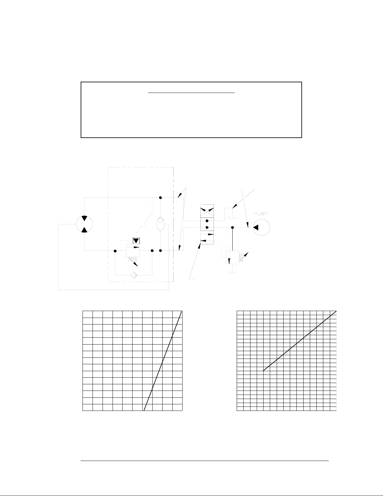
HYDRAULIC SYSTEM REQUIREMENTS
Refer to the performance charts below to properly match your hydraulic system to the winch performance. The
charts consist of:
(1) Line Pull first layer (lb.) vs. Working Pressure (PSI)
(2) Line Speed, first layer (FPM) vs. flow (GPM)
SYSTEM REQUIREMENTS
2500 PSI RELIEF VALVE SETTING
15 GPM FLOW RATE
DO NOT EXCEED 20 GPM--MOTOR AND WINCH MAY BE DAMAGED
10 MICRON NOMINAL FILTRATION
SYSTEM
RELIEF
3 POSITION
4 WAY VALVE
(MOTOR SPOOL)
MAX. FLOW &
PRESSURE AT
RATED LOAD:
15 GPM
2500 PSI
HIGH PRESSURE LINE
(.50 I.D. MINIMUM)
LOW PRESSURE LINE
(.75 I.D. MINIMUM)
PORT CONTROL
B
WITH BRAKE RELEASE SHUTTLE
MOTOR
BRAKE
PORT
A
PERFORMANCE WITH 24.0 CU. IN. HYDRAULIC MOTOR:
LINE PULL, LBS
FIRST LAYER
FIRST LAYER
LINE SPEED, FPM
WORKING PRESSURE, PSI
AT 15 GPM
500
0
0
250020001000 1500
3000
6000
FLOW, GPM
0
0
15510
5
10
15000
9000
12000
25
15
20
6
TYPICAL LAYOUT
PERFORMANCE CHARTS
Page 7

CONDITIONS POSSIBLE CAUSE CORRECTION/ACTION
DRUM WILL NOT ROTATE
AT NO LOAD
Winch not mounted squarely, causing end bearing
to bind up
Check mounting. Refer to Winch Mounting, page 4.
Brake damaged Inspect and replace brake
Gears damaged Inspect and replace damaged gears
DRUM WILL NOT ROTATE
UNDER LOAD
Load greater than rated capacity of winch Refer to Specifications page 3 for line pull rating.
Low hydraulic system pressure Check pressure. Refer to Hydraulic Systems per-
formance charts page 6.
WINCH RUNS TOO SLOW Low hydraulic system flow rate Check flow rate. Refer to Systerm Requirements and
Typical Layout page 6.
Motor worn out Replace motor
DRUM WILL NOT
FREESPOOL
Clutch not disengaged. Check Adjustment of Manual
Shifter, page 9.
Check Operation, page 5.
Winch not mounted squarely, causing end bearing
to bind up
Check mounting. Refer to Winch Mounting, page 4.
BRAKE WILL NOT
RELEASE
Brake damaged Inspect and replace brake
CABLE BIRDNESTS WHEN
CLUTCH IS DISENGAGED
Drag screw improperly adjusted Adjust nylon drag screw. Refer to Cable Installation,
page 4.
EXCESSIVE NOISE Hydraulic system flow too high Check flow rate. Refer to Typical Layout page 6.
DRUM CHATTERS IN
“REEL IN” DIRECTION
Low hydraulic system flow rate Check flow rate. Refer to Typical Layout page 6.
Low hydraulic system relief pressure setting Check relief valve setting.
OIL SEEPAGE FROM
BREATHER VENT OF
BRAKE HOUSING
Brake piston not sealing properly Replace o-ring and backup rings on brake piston.
Refer to pages 8 and 10.
GREASE SEEPAGE FROM
JOINTS IN MOTOR
Grease applied to seals during assembly by motor
manufacturer.
NONE. Normal condition during the first few times
the winch is operated.
TROUBLESHOOTING GUIDE
7
Page 8
INSTRUCTIONS FOR OVERHAUL RPH-15000 SERIES WINCH
Take note of mounting configurations for proper mounting of parts during re-assembly. Replace all gaskets, o-rings,
and seals during re-assembly.
Disconnect tube (item #44) from elbows (item #26) on bottom of brake (item #7) and valve (item #45). Remove motor
(item #31) from brake housing (item #7) by unscrewing
capscrews (item #20). Tap motor lightly to disengage.
Replace all gaskets, o-rings and seals with new ones during
re-assembly.
Remove coupling (item #25) from brake housing. Examine
coupling for signs of wear, replace if necessary. If necessary,
remove valve (item #45) from motor by removing capscrews
(item #16) and lockwashers (item #23). If valve is removed
make sure two square cross section o-rings remain seated in
their counter bores in valve.
Remove brake housing (item #7) from end bearing (item #3)
by unscrewing (6) capscrews (item #17) in a criss-cross
pattern (2 turns each) until all capscrews are removed from
brake housing. Remove brake parts from brake housing.
Examine brake discs (item #27) for signs of wear, and
replace if necessary. Examine o-rings (items #33 & #34)
and backup rings (items #35 & #36) for signs of wear.
Remove o-rings and backup rings from grooves in brake piston (item #4).
Remove and examine springs (items #42 & #43) for damage, replace if necessary.
Examine fitting (item #30) to assure that fittings are in proper
working condition, replace if necessary.
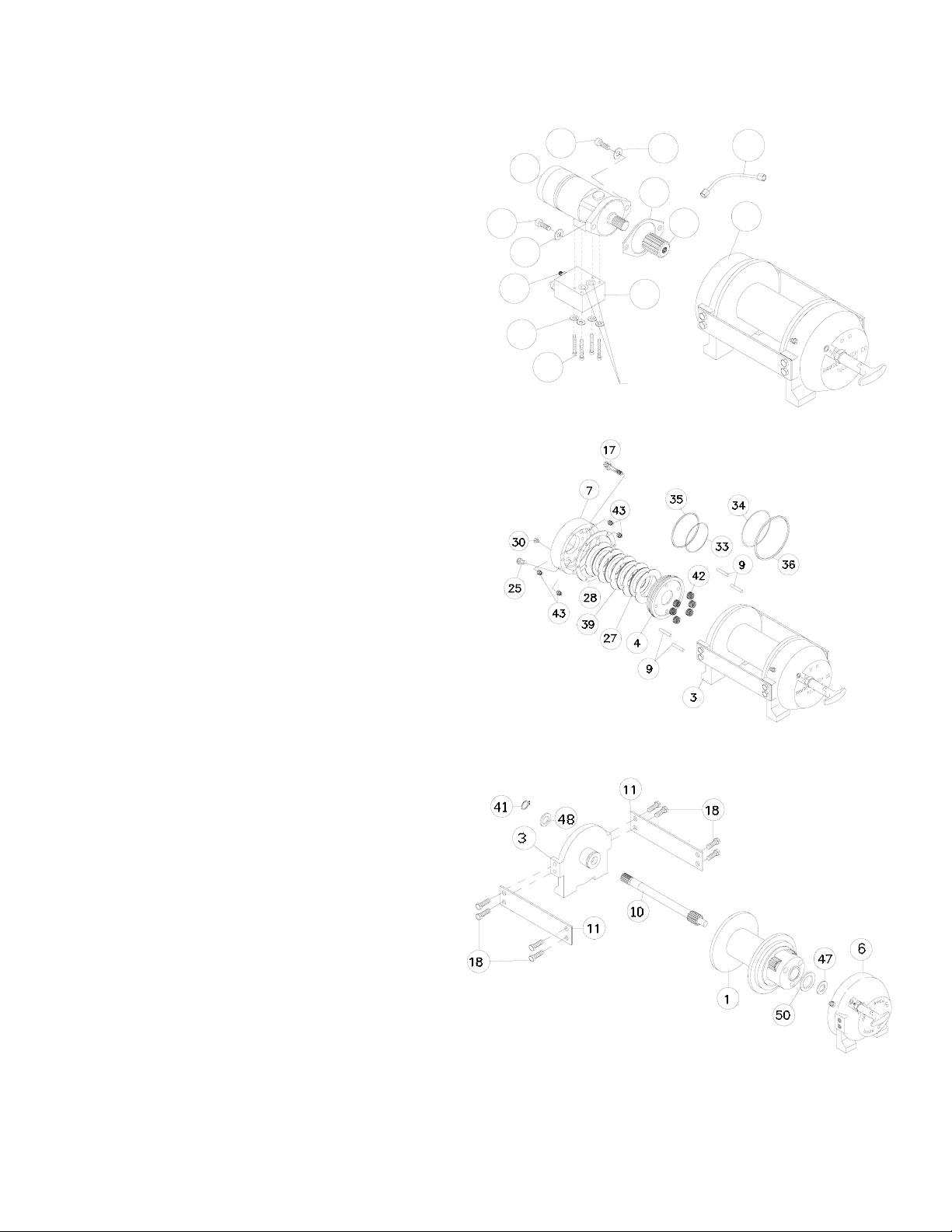
Remove tie plates (item #11) from end bearings (items #3 &
#6) by unscrewing capscrews (item #18), as shown.
Remove snap ring (item #41) and thrust washer (item #48)
from shaft. Slide motor end bearing (item #3) from drum
(item #1) and drum from gear housing end bearing (item
#6).
Remove input shaft (item #10) and thrust washers (item #47
& 50) from end bearing. Inspect gear teeth and splined end of
shaft for signs of wear. If damaged, it will be necessary to
replace shaft.
8
SQUARE CROSS
SECTION O-RING
16
24
31
26
20
45
20
29
25
24
7
44
23
Page 9
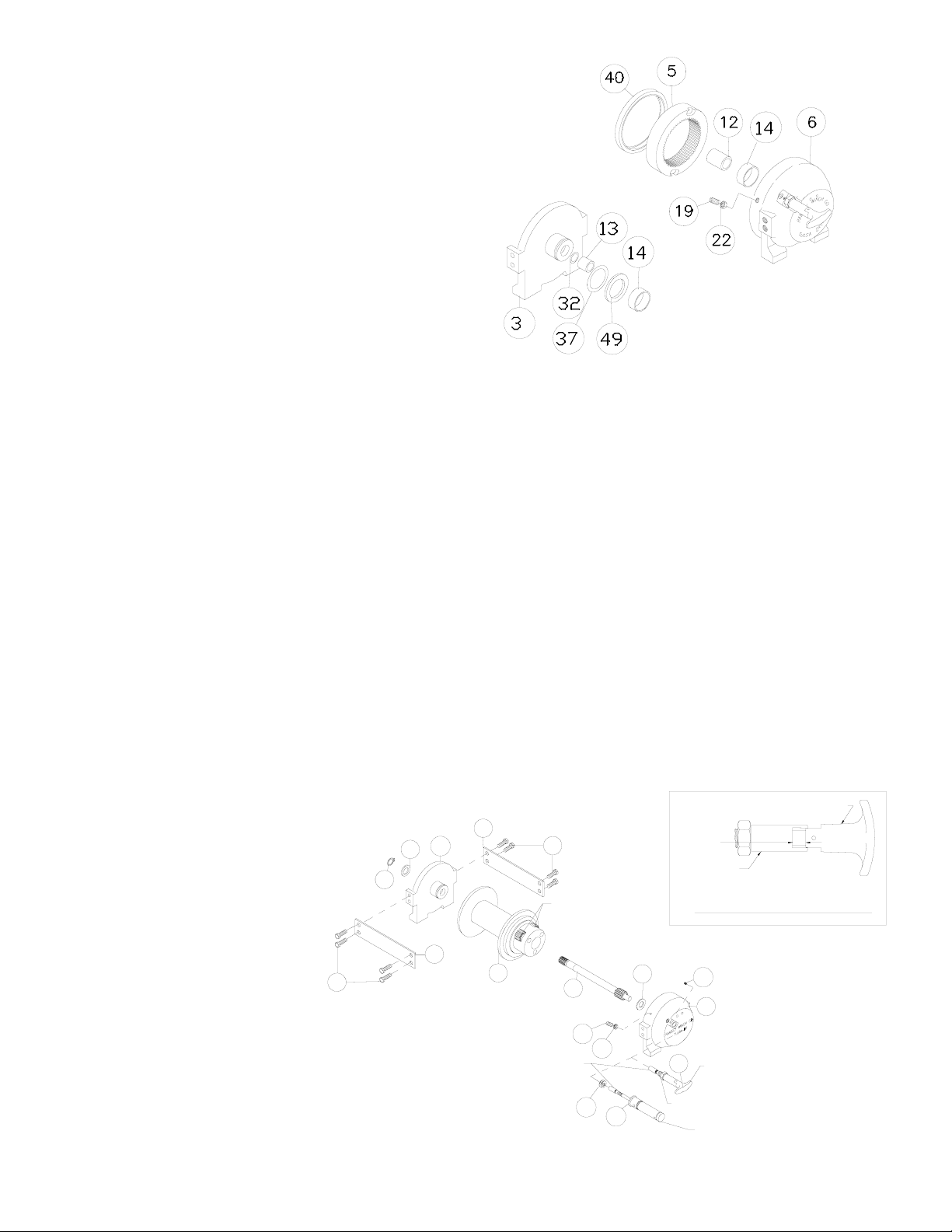
Remove o-ring (item #37), bushing (item #14) from outside of
motor end bearing (item #3), remove o-ring (item #32), bearing
(item #13) from inside of motor end bearing (item #3). Place
new, well oiled, o-ring (item #32) into groove inside of end
bearing and press new bearing (item #13) into end bearing.
Press bushing (item #14) onto end bearing and dip o-ring (item
#37) in oil and seat into groove of end bearing.
Remove seal (item #40) from gear housing end bearing (item
#6). Loosen nut (item #22) and remove nylon setscrew (item
#19) and remove ring gear (item #5) from gear housing end
bearing, if necessary. Remove bushing (item #14) and bearing
(item #12) from gear housing end bearing (item #6). Press
new bushing (item #14) and bearing (item #12) into place in
end bearing. Install ring gear and nylon setscrew and nut. Ring
gear must be fully seated in gear housing end bearing (item #6)
and slot in ring gear must NOT be aligned with clutch shifter
hole. Install new seal in gear housing end bearing, with sharp
edge of seal outward.
Generously apply grease (MOBILITH SHC 007) to teeth of ring gear (item #5), teeth of planet gears in drum (item #1) and to bushing in
gear housing end bearing (item #6). Apply a small amount of grease to base of bushing on motor end bearing (item #4). Apply grease to
teeth of gear and short end of shaft (item #10). Place gear end of shaft through thrust washer (item #49) and into bearing in end bearing
(item #6). Place drum over shaft and rotate drum to engage planet gears with output gear on shaft and with ring gear in end bearing.
Assemble end bearing (item #3) to drum assembly and use tie plates (item #11) and capscrews (item #18) to hold both end bearings
together. Tighten capscrews to 55 Ft. Lbs. (75 Nm.). Slide thrust washer (item #48) over end of shaft and against end bearing (item #3).
Place snap ring (item #41) into groove in splined end of shaft.
If necessary, remove and replace appropriate shifter assembly (item #2 or #3), as follows:
MANUAL CLUTCH SHIFTER ASSEMBLY
Remove by loosening setscrew (item #21), jam nut and unscrewing clutch shifter. Be sure slot in ring gear is not aligned with clutch shifter
hole. Rotate drum, if necessary, to insure hole and slot are not aligned. Reinstall clutch shifter with plunger, jam nut and handle positioned
in cylinder housing, as shown. Thread assembly (with handle engaged in cylinder slot) into the end bearing. Pull drum toward the brake
housing end bearing to remove play. Hold drum in the position and continue threading the shifter assembly in until the gap between the end
of the handle and cylinder is 7/16
+0
-1/16
inch and handle is in the horizontal position, as shown below. NOTE: This gap will vary with
drum endplay. With the drum pulled against the gear housing, the gap should be 3/8 inch. Lightly tighten jam nut. Rotate drum until handle
snaps fully into the engaged position. Pull handle out and rotate 90
o
. Verify that drum can be rotated freely (at least one full revolution) with
clutch shifter at DISENGAGED position. Securely tighten jam nut while holding the handle. Tighten setscrew securely. Re-check clutch
operation as described on page 5.
AIR CYLINDER SHIFTER ASSEMBLY
Remove by loosening setscrew (item #21),
jam nut and unscrewing clutch shifter. To
reinstall, thread air cylinder into housing.
Install one or two shims (item #44) under
cylinder head, if needed, to orient air cylinder port for pneumatic connections.
Tighten setscrew. Refer to page 5 and
check for proper operation of the clutch.
+0
-1/16
7/16
CYLINDER
HANDLE (HORIZONTAL)
MANUAL CLUTCH ADJUSTMENT
3
47
21
6
2
3
JAM NUT
MANUAL CLUTCH
SHIFTER
AIR-CYLINDER
CLUTCH SHIFTER
22
19
8
50
44
18
11
11
1
PLUNGER
PLANET
GEARS
18
41
9
Page 10
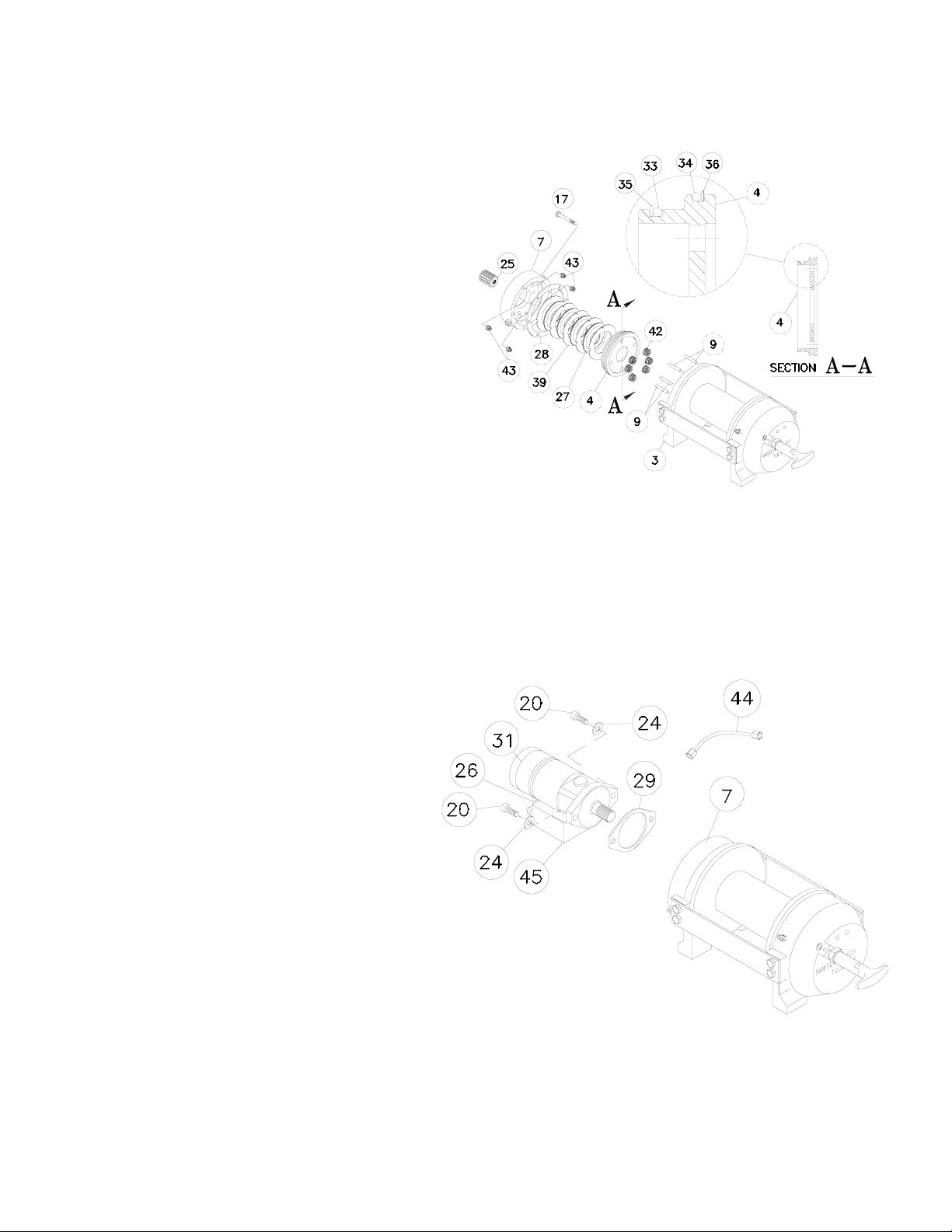
Set winch on gear housing end with motor end bearing (item #3) up. Insert (6) springs (item #42) into pockets of motor end
bearing (item #3), as shown, leaving top and bottom pockets empty. Install coupling (item #25) over splined end of shaft
(item #8). Put (4) brake pins (item #9) into (4) holes in motor end bearing. Install well-oiled o-ring (items #33 & #34) and
backup rings (items #35 & #36) into grooves in O.D. of piston (item #4). Place o-rings into portions of grooves nearest to
center of piston in both cases. See SECTION A-A below.
Piston (item #4), brake disc (item #27) and separator plates
(item #39) must be clean and free of grease and oil.
Place piston over pins (item #9) and on top of springs (item
#42). Place separator plates (item #39) and brake disc alternately on top of piston, as shown below. Press larger diameter end of (4) springs (item #43) into pockets in brake housing (item #7). Place gasket (item #28) on top of end bearing
(item #3). Place brake housing over brake parts with fitting
ports downward toward mounting feet. Align mounting holes
and force brake housing down onto end bearing (item #3).
Apply 271 Loc-tite to 6 capscrews (item #17) and finger
tighten until flush with surface of brake housing. Torque capscrews (2 turns each) in a criss-cross pattern until a torque of
30 ft-lbs., per capscrew, is achieved.
Place gasket (item #29) into position on mounting surface of motor (item #31). Slide motor shaft into coupling and attach
motor to brake housing (item #7). Use (2) capscrews (item #20) with lockwashers (item #24) and torque to 87 ft. lbs. (118
Nm) each. Securely connect tube (item #44) to elbows (item #26) in valve (item #45) and in bottom of brake housing (item
#7).
Apply at least 550 PSI hydraulic system pressure to release brake and verify that brake releases, by observing that the winch
drum rotates.
10
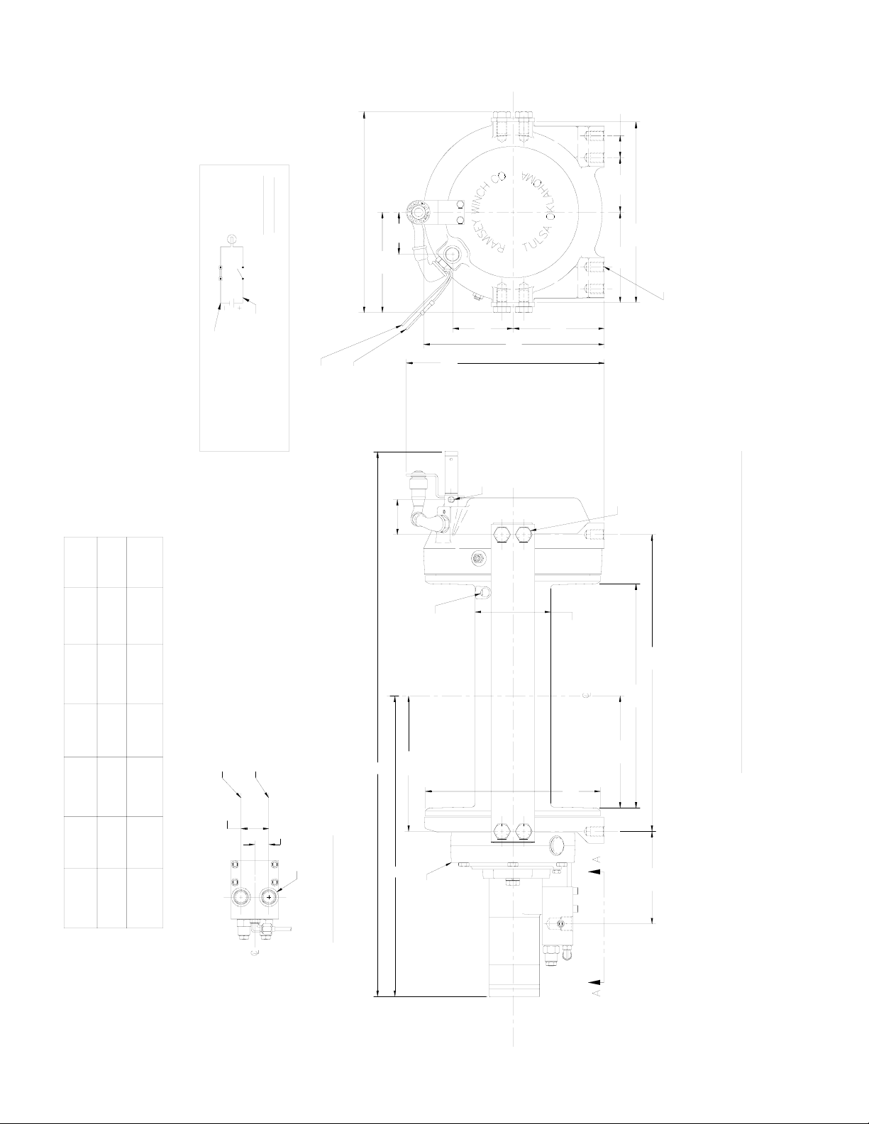
Page 11
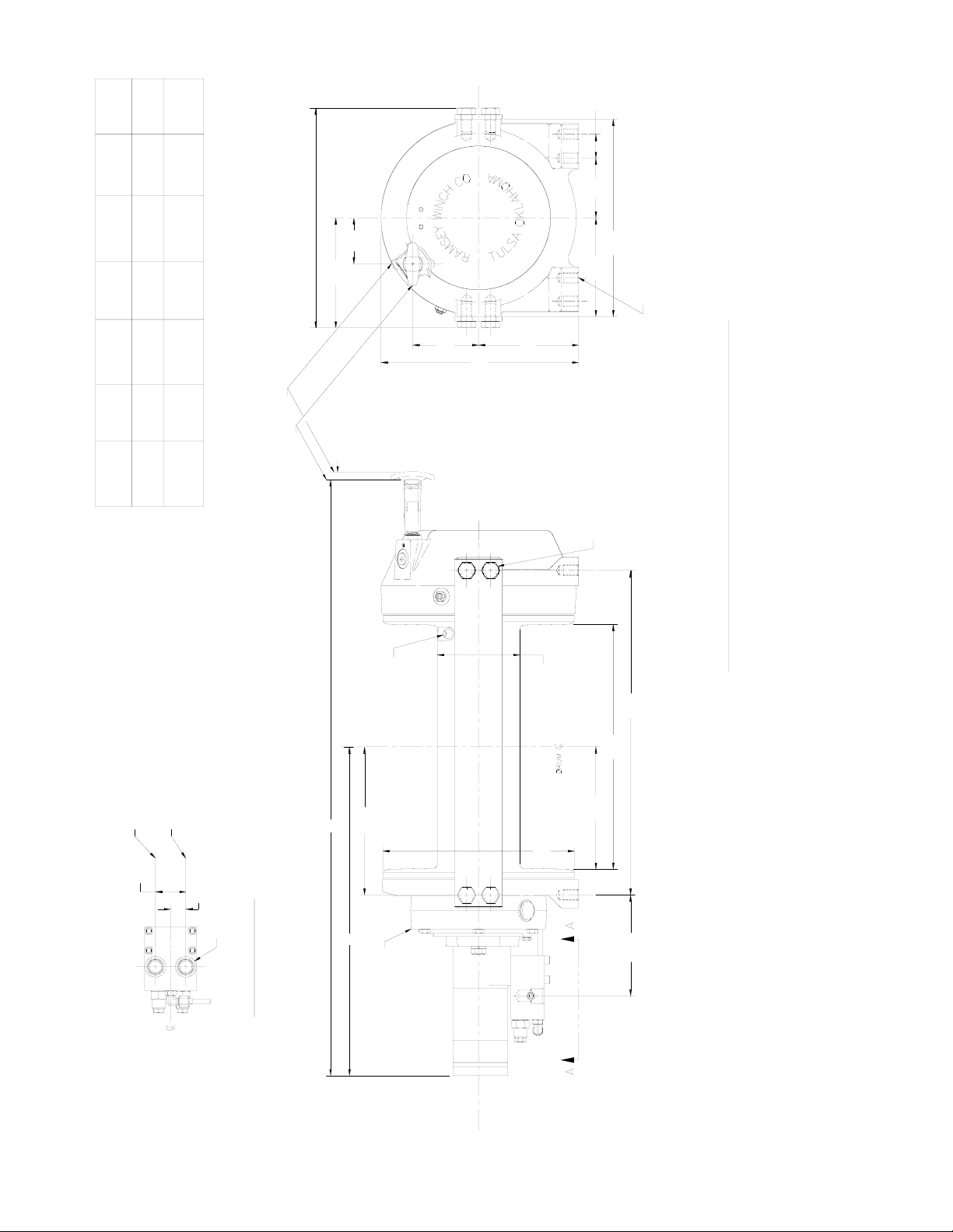
C
DIA. CABLE HOLE
15,7
.62
ROTATION VIEWED FROM MOTOR END
PRESSURE IN GIVES CLOCKWISE DRUM
ROTATION VIEWED FROM MOTOR END
PRESSURE IN GIVES COUNTER-CLOCKWISE DRUM
22,4
.88
44,5
1.75
TAPPED HOLE (4-PLACES EACH END BEARING)
5/8-11UNC X .88" (22,4MM) DEEP
TAPPED HOLE (4-PLACES EACH SIDE OF WINCH)
5/8-11UNC X .88" (22,4MM) DEEP
289,1
146,1
5.75
11.38
144,5
5.69
(TYP)
87,4
*3.44
35,1
*1.38
(TYP)
5.81
147,5
A
B
STATIC LOAD
HOLDING BRAKE
12,7
.50
CLUTCH DISENGAGED POSITION
CLUTCH ENGAGED POSITION
289,1
11.38
96,3
3.79
67,3
6.33
160,8
2.65
321,5
12.66
DIMENSIONS SHOWN ARE INCHES OVER MILLIMETERS
E
279,4
11.00
D
FLANGE DIA.
F
BARREL DIA.
120,7
4.75
MOTOR CONTROL VALVE DETAIL
VIEW A-A
O-RING PORT (2-PLACES)
7/8-14 SAE STRAIGHT THREAD
WINCH
DRUM DIM DIM DIM DIM DIM DIM
SIZE A B C D E F*
STD 34.32 18.93 8.53 7.06 14.12 18.69
871,7 480,8 216,7 179,3 358,6 474,7
"Y" 29.07 16.37 5.97 4.50 9.00 13.56
738,3 415,7 151,6 114,3 228,6 344,4
* NOTE: THESE HOLE LOCATIONS MUST BE HELD WITHIN ±.03" (0,8 mm) OF
TRUE POSITION. RECOMMENDED MOUNTING HOLE DIAMETER IS .66" (16,8 mm).
11
RPH-15000 MANUAL SHIFTER
Page 12
2.19
289,1
11.38
96,3
3.79
67,3
6.33
160,8
2.65
ATTACH TO 12V DC (+)
(SEE ELECTRICAL SCHEMATIC)
ATTACH TO GROUND (SEE
321,5
12.66
DIMENSIONS SHOWN ARE INCHES OVER MILLIMETERS
5.81
147,5
A
B
STATIC LOAD
HOLDING BRAKE
ENGAGED AND "OFF" WHEN CLUTCH IS DISENGAGED.
NOTE: LIGHT SHOULD BE "ON" WHEN CLUTCH IS
RECEIVE 12V DC WHEN PTO IS ENGAGED.
ATTACH TO PTO INDICATOR SWITCH TO
12V BATTERY
WIRE SUPPLIED BY CUSTOMER)
ATTACH TO GROUND (16 GA.
SWITCH
SCHEMATIC
ELECTRICAL
IS ENGAGED)
(ON WHEN CLUTCH
INDICATOR LIGHT
CONNECTOR
BUTT
* NOTE: THESE HOLE LOCATIONS MUST BE HELD WITHIN ±.03" (0,8 mm) OF
TRUE POSITION. RECOMMENDED MOUNTING HOLE DIAMETER IS .66" (16,8 mm).
"Y" 29.07 16.37 5.97 4.50 9.00 13.56
738,3 415,7 151,6 114,3 228,6 344,4
STD 34.32 18.93 8.53 7.06 14.12 18.69
871,7 480,8 216,7 179,3 358,6 474,7
DIM DIM DIM DIM DIM DIM
A B C D E F*
C
DIA. CABLE HOLE
14,2
.56
ROTATION VIEWED FROM MOTOR END
PRESSURE IN GIVES CLOCKWISE DRUM
ROTATION VIEWED FROM MOTOR END
PRESSURE IN GIVES COUNTER-CLOCKWISE DRUM
22,4
.88
44,5
1.75
TAPPED HOLE (4-PLACES EACH END BEARING)
5/8-11UNC X .88" (22,4MM) DEEP
TAPPED HOLE (4-PLACES EACH SIDE OF WINCH)
5/8-11UNC X .88" (22,4MM) DEEP
289,1
146,1
5.75
11.38
144,5
5.69
(TYP)
87,4
*3.44
35,1
*1.38
(TYP)
ELECTRICAL SCHEMATIC)
12.45
316,2
CLUTCH). CAUTION: AIR PRESSURE
MUST NOT EXC EED 150 PSI.
PRESSURE LINE TO DISENGAGE
1/8-27NPT PORT
(CONNECT 80 TO 150 PSI
55,5
E
279,4
11.00
D
FLANGE DIA.
DRUM
F
BARREL DIA.
120,7
4.75
MOTOR CONTROL VALVE DETAIL
VIEW A-A
O-RING PORT (2-PLACES)
7/8-14 SAE STRAIGHT THREAD
WINCH
12
RPH-15000 AIR SHIFTER
Page 13
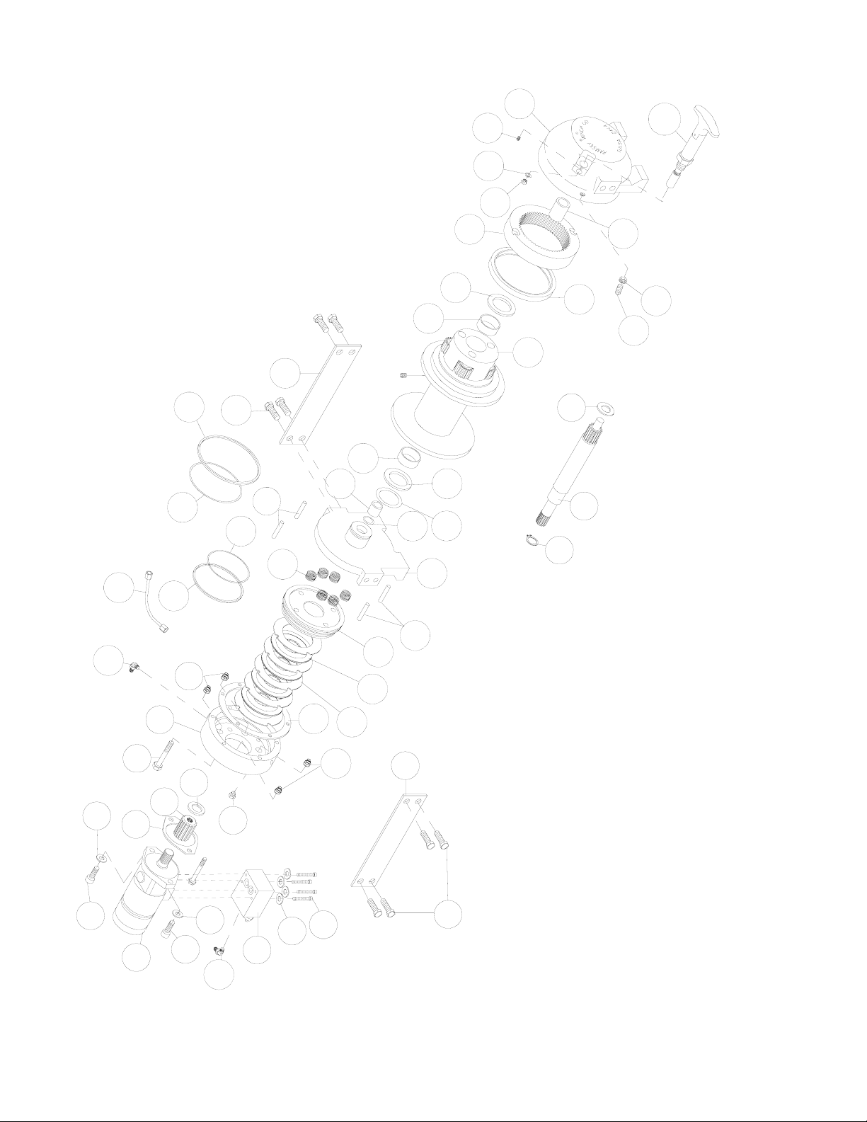
24
18
45
26
16
23
2
38
6
21
3
42
33
9
36
7
17
29
48
25
24
43
26
35
34
44
13
32
10
47
41
37
18
14
11
15
1
50
40
22
19
12
46
5
49
20
31
20
39
11
27
9
4
28
43
30
13
RPH-15000 MANUAL SHIFTER
Page 14

14
PARTS LIST RPH 15000 WITH MANUAL CLUTCH SHIFTER
ITEM QTY. PART NO. DESCRIPTION
1 1 234173 STD. DRUM ASS'Y.
1 234200 "Y" DRUM ASS'Y.
2 1 276052 SHIFTER ASS'Y. - MANUAL
3 1 296611 END BEARING - MOTOR
4 1 306042 PISTON - BRAKE
5 1 334177 GEAR-RING
6 1 338297 HOUSING - GEAR, END BEARING
7 1 338302 HOUSING - BRAKE
9 4 346045 PIN - BRAKE
10 1 357518 SHAFT - INPUT (STD. DRUM)
1 357521 SHAFT - INPUT ("Y" DRUM)
11 2 395236 TIE PLATE (STD. DRUM)
2 474224 TIE PLATE ("Y" DRUM)
12 1 402120 BEARING
13 1 402121 BEARING - MOTOR END BEARING
14 1 412095 BUSHING - DRUM (MTR. END)
15 1 412096 BUSHING - DRUM (G.HSG. END)
16 4 414159 CAPSCREW - 5/16-18 X 1-1/2 LG HX HD GR5 Z/P
17 6 414303 CAPSCREW - 3/8-16NC X 2-1/2 LG. HX HD GR5 PLTD
18 8 414664 CAPSCREW - 5/8-11NC X 1 LG. HX. HD., GR. 5
19 1 414926 SETSCREW - 3/8-16NC X 1 LG., SOCKET, NYLON
20 2 414948 CAPSCREW - 1/2-13NC X 1-1/4 LG., HX. SOC. HD.
21 1 416016 SETSCREW - 1/4-20NC X 1/4 LG., HX. SOC. HD.
22 1 418036 NUT 3/8 - 16NC HEX. JAM
23 4 418063 LOCKWASHER - 5/16 MED SECT Z/P
24 2 418218 LOCKWASHER - 1/2 ID MED. SECT.
25 1 431015 COUPLING - BRAKE
26 2 432018 FITTING - 7/16 ELBOW
27 4 438022 DISC - BRAKE
28 1 442220 GASKET - BRAKE
29 1 442223 GASKET - MOTOR
30 1 456038 FITTING - VENT
31 1 458090 MOTOR-HYDRAULIC
32 1 462056 O-RING
33 1 462057 O-RING
34 1 462058 O-RING
35 1 462059 O-RING
36 1 462060 O-RING
37 1 462061 O-RING (DRUM)
38 1 472052 PLUG
39 5 474111 PLATE SEPARATOR
40 1 486081 SEAL-GEAR HSG.
41 1 490037 SNAP RING
42 6 494110 SPRING - BRAKE
43 4 494112 SPRING
44 1 509009 TUBE ASSEMBLY
45 1 516013 VALVE - MOTOR CONTROL
46 1 518037 THRUST WASHER
47 1 518047 THRUST WASHER
48 1 518052 THRUST WASHER
49 1 518053 THRUST WASHER (MTR. END)
50 1 518054 THRUST WASHER (G. HSG. END)
Page 15
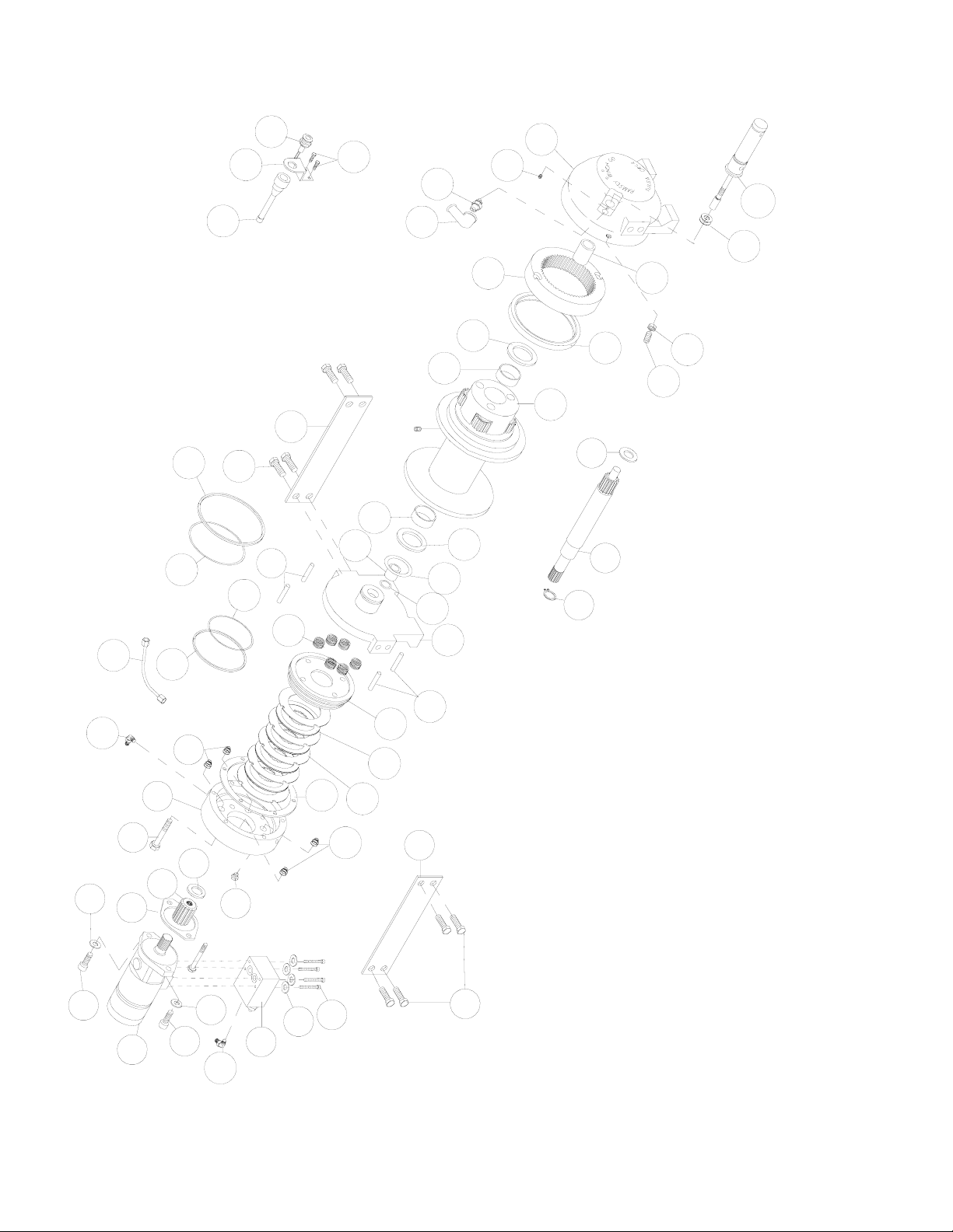
53
26
20
50
47
32
8
23
3
44
14
34
28
18
25
22
33
15
40
12
29
10
5
30
39
20
15
12
16
1
54
43
24
21
13
7
4
46
35
10
38
9
1931
52
27
26
47
28
37
36
49
6
17
42
2
11
51
45
40
48
15
RPH-15000 AIR SHIFTER
Page 16

16
PARTS LIST RPH 15000 WITH AIR-CYLINDER CLUTCH SHIFTER
ITEM QTY. PART NO. DESCRIPTION
1 1 234173 STD. DRUM ASS'Y.
1 234200 “Y” DRUM ASS'Y.
2 1 236020 LIGHT ASS'Y
3 1 276053 SHIFTER ASS'Y. - AIR
4 1 296611 END BEARING - MOTOR
5 1 306042 PISTON - BRAKE
6 1 312526 BRACKET - LIGHT MTG.
7 1 334177 GEAR-RING
8 1 338297 HOUSING -GEAR, END BEARING
9 1 338302 HOUSING - BRAKE
10 4 346045 PIN - BRAKE
11 1 357518 SHAFT - INPUT (STD. DRUM)
1 357521 SHAFT - INPUT (“Y” DRUM)
12 2 395236 TIE PLATE (STD. DRUM)
2 395236 TIE PLATE (“Y” DRUM)
13 1 402120 BEARING
14 1 402121 BEARING - MOTOR END BEARING
15 1 412095 BUSHING - DRUM (MTR. END)
16 1 412096 BUSHING - DRUM (G.HSG. END)
17 2 414036 CAPSCREW - 1/4-20NC X 1/2 HX HD GR5 F/B
18 4 414159 CAPSCREW - 5/16-18 X 1-1/2 LG HX HD GR5 Z/P
19 6 414303 CAPSCREW - 3/8-16NC X 2-1/2 LG. HX HD GR5 PLTD
20 8 414664 CAPSCREW - 5/8-11NC X 1 LG. HX. HD., GR. 5
21 1 414926 SETSCREW - 3/8-16NC X 1 LG., SOCKET, NYLON
22 2 414948 CAPSCREW - 1/2-13NC X 1-1/4 LG., HX. SOC. HD.
23 1 416016 SETSCREW - 1/4-20NC X 1/4 LG., HX. SOC. HD.
24 1 418036 NUT 3/8 - 16NC HEX. JAM
25 4 418063 LOCKWASHER - 5/16 MED SECT Z/P
26 2 418218 LOCKWASHER - 1/2 ID MED. SECT.
27 1 431015 COUPLING - BRAKE
28 2 432018 FITTING - 7/16 ELBOW
29 4 438022 DISC - BRAKE
30 1 442220 GASKET - BRAKE
31 1 442223 GASKET - MOTOR
32 1 456038 FITTING - VENT
33 1 458090 MOTOR-HYDRAULIC
34 1 462056 O-RING
35 1 462057 O-RING
36 1 462058 O-RING
37 1 462059 O-RING
38 1 462060 O-RING
39 1 462061 O-RING (DRUM)
40 5 474111 PLATE SEPARATOR
41 1 482013 GROMMET
42 1 482045 RUBBER BOOT
43 1 486081 SEAL-GEAR HSG.
44 2 488007 SHIM
45 1 490037 SNAP RING
46 6 494110 SPRING - BRAKE
47 4 494112 SPRING
48 1 504021 SWITCH ASS'Y
49 1 509009 TUBE ASSEMBLY
50 1 516013 VALVE - MOTOR CONTROL
51 1 518047 THRUST WASHER
52 1 518052 THRUST WASHER
53 1 518053 THRUST WASHER (MTR. END)
54 1 518054 THRUST WASHER (G. HSG. END)
Page 17
MANUEL D’UTILISATION,
DE DÉPANNAGE
ET D’ENTRETIEN
TREUIL À PLANÉTAIRE MODÈLE RPH-15000
MISE EN GARDE : ASSUREZ-VOUS DE LIRE ET DE COMPRENDRE CE MANUEL AVANT D’INSTALLER
ET D’UTILISER LE TREUIL. N’OUBLIEZ PAS LES AVERTISSEMENTS ET MISES EN GARDE.
Ramsey Winch Company
P.O. Box 581510 - Tulsa, OK 74158-1510 USA
Phone: (918) 438-2760 - Fax (918) 438-6688
Visit us at http://www.ramsey.com
Page 18

TABLE DES MATIÈRES
INTRODUCTIONS . . . . . . . . . . . . . . . . . . . . . . . . . . . . . . . . . . . . . . . . . . . . . . . . . . . . . . . . . . . . . . . . . . . . . .19
INFORMATIONS DE GARANTIE . . . . . . . . . . . . . . . . . . . . . . . . . . . . . . . . . . . . . . . . . . . . . . . . . . . . . . . . . . .19
CARACTÉRISTIQUES TECHNIQUES . . . . . . . . . . . . . . . . . . . . . . . . . . . . . . . . . . . . . . . . . . . . . . . . . . . . . . . .19
AVERTISSEMENTS . . . . . . . . . . . . . . . . . . . . . . . . . . . . . . . . . . . . . . . . . . . . . . . . . . . . . . . . . . . . . . . . . . . .19
FIXATION DU TREUIL . . . . . . . . . . . . . . . . . . . . . . . . . . . . . . . . . . . . . . . . . . . . . . . . . . . . . . . . . . . . . . . . . . .20
INSTALLATION DU CÂBLE . . . . . . . . . . . . . . . . . . . . . . . . . . . . . . . . . . . . . . . . . . . . . . . . . . . . . . . . . . . . . . .20
ENTRETIEN DU TREUIL . . . . . . . . . . . . . . . . . . . . . . . . . . . . . . . . . . . . . . . . . . . . . . . . . . . . . . . . . . . . . . . . .21
FONCTIONNEMENT . . . . . . . . . . . . . . . . . . . . . . . . . . . . . . . . . . . . . . . . . . . . . . . . . . . . . . . . . . . . . . . . . . . .21
SYSTÈMES HYDRAULIQUES . . . . . . . . . . . . . . . . . . . . . . . . . . . . . . . . . . . . . . . . . . . . . . . . . . . . . . . . . . . . .22
MONTAGE HYDRAULIQUE TYPE . . . . . . . . . . . . . . . . . . . . . . . . . . . . . . . . . . . . . . . . . . . . . . . . . . . . . . . . . .22
DIAGRAMMES DE PERFORMANCES . . . . . . . . . . . . . . . . . . . . . . . . . . . . . . . . . . . . . . . . . . . . . . . . . . . . . . .22
GUIDE DE RÉSOLUTION DES PROBLÈMES . . . . . . . . . . . . . . . . . . . . . . . . . . . . . . . . . . . . . . . . . . . . . . . . . .23
INSTRUCTIONS DE RÉVISION DES TREUILS . . . . . . . . . . . . . . . . . . . . . . . . . . . . . . . . . . . . . . . . . . . . . .24-26
PLAN COTÉ . . . . . . . . . . . . . . . . . . . . . . . . . . . . . . . . . . . . . . . . . . . . . . . . . . . . . . . . . . . . . . . . . . . . . . .27-28
LISTE ET SCHÉMA DES PIÈCES . . . . . . . . . . . . . . . . . . . . . . . . . . . . . . . . . . . . . . . . . . . . . . . . . . . . . . . .29-32
GARANTIE LIMITÉE
RAMSEY WINCH garantit chaque treuil RAMSEY neuf contre tout défaut de matériau et de fabrication pendant une période d’un (1) an à
partir de la date d’achat. L'obligation aux termes de cette garantie, statutaire ou autre, est limitée au remplacement ou à la réparation à l’usine du fabricant, ou à un endroit désigné par le fabricant, de la pièce qui semblera présenter un défaut de fabrication ou de matériau, suite
à l'inspection effectuée par le fabricant.
Cette garantie n’oblige pas RAMSEY WINCH à s’acquitter des frais de main-d'ouvre ou de transport liés au remplacement ou à la réparation des pièces défectueuses, et ne s'applique pas à un produit ayant subi des réparations ou des modifications (sauf si elles ont été
autorisées par le fabricant), ou en cas de mauvaise utilisation de l’équipement, de négligence ou de matériel mal installé.
RAMSEY WINCH ne pourra en aucun cas être tenue responsable des dommages particuliers et indirects. RAMSEY WINCH n’émet aucune
garantie au sujet des accessoires et portant par exemple sur les garanties de leurs fabricants respectifs. RAMSEY WINCH s’efforce de
poursuivre une politique d’amélioration constante et se réserve par conséquent le droit d'améliorer ses produits par le biais de modifications de leur conception ou des matériaux employés, selon les besoins, et sans être obligée d'incorporer ces modifications aux produits
fabriqués précédemment.
En cas d’intervention sur le terrain à la demande de l’acquéreur, et si la défaillance s’avère ne pas provenir du produit RAMSEY WINCH,
l’acquéreur s’engage à s’acquitter auprès du représentant des frais correspondant au temps et aux dépenses.
Les factures d'entretien, de main-d’ouvre et autres frais engagés par l’acquéreur sans l'accord ou l'autorisation de RAMSEY WINCH ne
seront pas acceptées.
Reportez-vous à la carte de garantie pour les détails.
Page 19

VEUILLEZ LIRE ATTENTIVEMENT CE MANUEL.
Ce manuel contient des conseils utiles pour l'utilisation efficace de votre treuil Ramsey ; il aborde aussi les procédures de sécurité à connaître absolument avant l’utilisation d’un tel équipement.
INFORMATIONS DE GARANTIE
Les treuils Ramsey sont conçus et fabriqués selon des spécifications rigoureuses. Ils font tous l’objet d’un travail soigné et
compétent. En cas de besoin, la procédure de recours en garantie est détaillée au verso de votre carte de garantie préadressée
à port payé. Veuillez lire et remplir la carte de garantie ci-jointe, et l'envoyer à Ramsey Winch Company. En cas de problème
avec votre treuil, suivez les instructions fournies afin d’obtenir un service rapide de recours en garantie.
*CARACTÉRISTIQUES TECHNIQUES
Remarque : les tractions nominales indiquées sont uniquement pour le treuil. Consultez le fabricant du câble pour les caractéristiques nomi-
nales de ce dernier.
AVERTISSEMENTS :
L’EMBRAYAGE DOIT ÊTRE ENTIÈREMENT ENCLENCHÉ AVANT DE COMMENCER TOUT TREUILLAGE.
NE RELÂCHEZ JAMAIS L’EMBRAYAGE EN PRÉSENCE D’UNE CHARGE.
NE LAISSEZ PAS L’EMBRAYAGE ENCLENCHÉ LORSQUE LE TREUIL N’EST PAS UTILISÉ.
NE VOUS PLACEZ JAMAIS SOUS UNE CHARGE SOULEVÉE NI À PROXIMITÉ.
RESTEZ À L’ÉCART DU CÂBLE LORS DU TREUILLAGE. N’ESSAYEZ PAS DE GUIDER LE CÂBLE.
NE DÉPASSEZ PAS LES CARACTÉRISTIQUES DE TRACTION NOMINALES MAXIMALES INDIQUÉES DANS LE TABLEAU.
N’UTILISEZ PAS LE TREUIL POUR SOULEVER, MAINTENIR OU TRANSPORTER DES PERSONNES.
IL CONVIENT DE CONSERVER AU MINIMUM CINQ TOURS DE CÂBLE AUTOUR DU TAMBOUR POUR MAINTENIR LA
CHARGE. L’ATTACHE DU CÂBLE N’EST PAS CONÇUE POUR ASSURER LE MAINTIEN D’UNE CHARGE.
DANS LES APPLICATIONS DE TRANSPORT D’AUTOMOBILES, VEILLEZ À BIEN FIXER LE VÉHICULE SUR LE PORTE-
VOITURES. LA CHARGE IMPOSÉE AU CÂBLE DU TREUIL NE DOIT PAS ÊTRE MAINTENUE PENDANT LE TRANSPORT. N’UTILISEZ PAS LE TREUIL COMME DISPOSITIF D’ATTACHE.
LORSQUE VOUS TREUILLEZ UNE LOURDE CHARGE, PLACEZ UNE COUVERTURE, UNE VESTE OU UNE BÂCHE SUR LE
CÂBLE À ENVIRON 1,8 m DU CROCHET.
ÉVITEZ TOUS RISQUES DE GLISSEMENT DE LA CHARGE OU D’À-COUPS À SON NIVEAU, CAR ILS POURRAIENT
S’AVÉRER DANGEREUX.
19
(lbs.)
…………………………………………………………………
15,000
(Kg.) …………………………………………………………….. 6,800
Démultiplication 7.7:1
300 lbs. (136 Kg)
290 lbs. (131 Kg)
123456**
lbs. 15,000 12,600 10,800 9,500 8,500 7,600
Kg. 6,800 5,710 4,890 4,300 3,850 3,440
ft. 35 75 125 180 240 310
m 102238547394
ft. 20 45 75 110 150 195
m 6 13 22 33 45 60
FPM252934394448
MPM 7,6 8,8 10,3 11,8 13,4 14,6
*Ces caractéristiques techniques sont basées sur un câble EIPS de 13 mm et sur un
moteur de 393 cm³/tr.
* Capacité De Câble Par Couche
** La sixième couche n’est pas conforme à la norme SAE J706.
Traction du câble
nominale
STD. Drum ……..…….....……………..…….
"Y" Drum ………………..……….…………..
……………………………………………………………
Poids (sans le câble)
Couche de câble
*Traction Nominale
Par Couche De
Câble
STD. DRUM
* Vitesse du
câble (à 56 l/min)
"Y" DRUM
Page 20
FIXATION DU TREUIL
INSTRUCTIONS DE MONTAGE IMPORTANTES POUR MAINTENIR L’ALIGNEMENT DES ÉLÉMENTS DU TREUIL À PLANÉTAIRE :
Ce treuil doit absolument être monté correctement
afin que les trois principales parties soient alignées
(l’extrémité du carter d’embrayage, le tambour du
câble et l’extrémité de la boîte d'engrenages).
À des fins de conformité, s’il s’agit d’un montage de
treuil intermédiaire, il convient de fixer au moins une
plaque de serrage aux pieds de fixation au bas du
treuil pour maintenir l’alignement. REMARQUE : si le
treuil est installé sur pieds, au moins une plaque de
serrage doit être placée au point intermédiaire pour
maintenir l’alignement. Il est toujours souhaitable d’utiliser les deux plaques de serrage pour l’installation
finale.
Il est conseillé d’utiliser le coffret de montage sur
cornières, nº 251173 pour faciliter l’installation du
treuil. Ce coffret permet de s’adapter aux installations
verticales ou intermédiaires, et constitue une surface
de montage droite et solide.
Si vous installez le treuil sans le coffret de cornières
Ramsey recommandé, il convient alors d’utiliser les trous de fixation décrits en page 27-28. La surface de fixation doit être plane, à 0,38 mm
près, et suffisamment rigide pour ne pas fléchir. Si une plaque d’acier est employée pour l’installation sur pied, elle doit mesurer 19 mm d’épaisseur. Pour ce type de montage, vous aurez besoin de huit vis d’assemblage 5/8-11NC x 1,5 po de long, grade 5, avec leurs rondelles de
sécurité. Ces vis devront être serrées à un couple de 235 Nm.
REMARQUE : si des cornières ou une plaque d’acier sont utilisées pour l’installation du treuil, les plaques de serrage fournies doivent être
fixées aux cales de montage restantes, qu’elles soient latérales ou inférieures.
INSTALLATION DU CÂBLE
1. Déroulez le câble sur le sol pour éviter qu'il ne se
torde. Recouvrez bien l’extrémité du câble opposée
au crochet d’un ruban adhésif plastique ou de type
équivalent pour éviter qu’il ne s’effiloche.
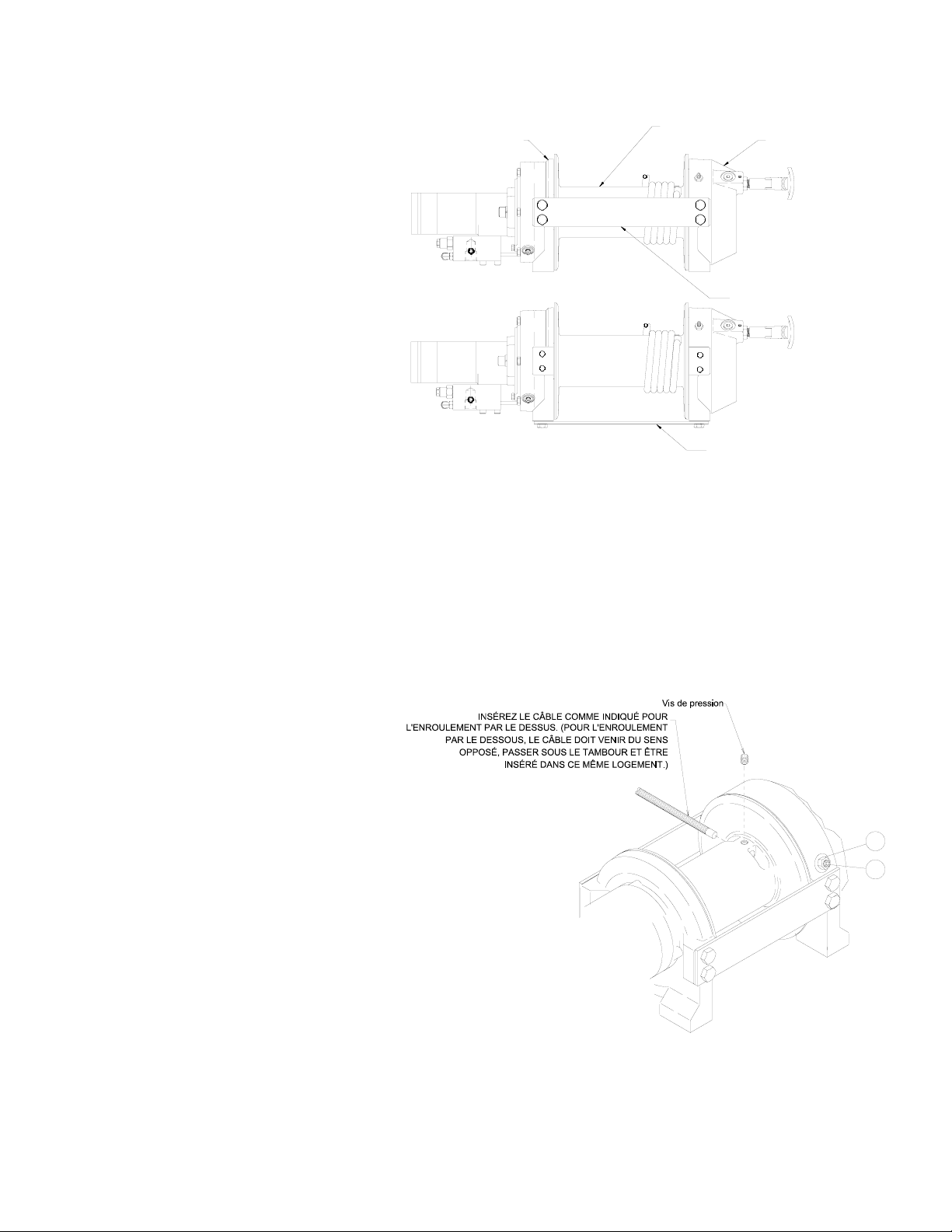
2. Placez l’extrémité effilée du câble dans le trou du
tambour, comme indiqué ci-dessous. Utilisez une vis
de pression à tête creuse hexagonale 3/8-16 NC x ½
po de long (sur le tambour 234171) pour fixer le
câble au tambour.
3. Faites tourner avec précaution le treuil dans le sens
de l’enroulement. Conservez une tension sur l’extrémité du câble et enroulez tout le câble sur le tambour en veillant à former des couches régulières.
Une fois le câble installé, vérifiez que le tambour tourne
librement. Désenclenchez l’embrayage et tirez sur le
câble en marchant. Si le câble se détend et forme des
boucles autour du tambour, desserrez le contre-écrou
(pièce nº 19) et tournez la vis en Nylon (pièce nº 22)
dans le sens des aiguilles d’une montre pour augmenter
le frottement sur le tambour. Si le frottement est trop important, desserrez cette vis en la tournant dans le sens inverse des aiguilles d’une
montre. Serrez le contre-écrou une fois le réglage correct obtenu.
MISE EN GARDE : tout serrage excessif du contre-écrou pourrait fausser le filet de la vis de pression en Nylon.
EXTRÉMITÉ MOTEUR
PLAQUE DE SERRAGE LATÉRALE
PLAQUE DE SERRAGE AU PIED (BASE)
EXTRÉMITÉ BOÎTE
TAMBOUR DU CÂBLE
MONTAGE SUR PIED
MONTAGE INTERMÉDIAIRE
D’ENGRENAGES
19
22
20
Page 21

ENTRETIEN
1. Examinez l’état du câble et lubrifiez-le fréquemment. Tout câble effiloché ou comportant des brins brisés doit être remplacé immédiate-
ment.
2. Assurez-vous que l’embrayage est complètement enclenché. Reportez-vous aux instructions de la rubrique FONCTIONNEMENT, ci-
dessus, selon le type d’embrayage. POUR LES EMBRAYAGES MANUELS UNIQUEMENT : tous les mois, désenclenchez l'embrayage,
placez plusieurs gouttes d'huile sur l'arbre et manipulez plusieurs fois l'embrayage pour lubrifier l’intérieur du cylindre.
3. Assurez-vous que le câble ne se détend pas pour former de larges boucles lors du déroulement libre. Reportez-vous à la page 20.
4. Remplacez les bagues du tambour ainsi que les joints lorsqu'ils commencent à perdre de la graisse. Reportez-vous aux INSTRUC-
TIONS DE RÉVISIONS en page 26-28. Le cas échéant, ajoutez du lubrifiant, Mobilith SHC 007, aux engrenages.
FONCTIONNEMENT
Pour vous familiariser avec votre treuil, il est vivement conseillé de l’essayer avant de vraiment l’utiliser. Préparez votre essai à l’avance.
N’oubliez pas que vous entendez votre treuil autant que vous le voyez fonctionner. Apprenez à reconnaître le son d'une traction légère et
régulière, celui d'une lourde charge ou encore celui provoqué par des à-coups ou une déviation de la charge. Évitez tous risques de glissements de la charge ou d’à-coups à son niveau, car ils pourraient représenter de dangereuses conditions.
L’embrayage du treuil permet un déroulement rapide du câble, à partir du tambour, afin de le fixer à une charge. L’embrayage est actionné au
moyen de sa manette ou du cylindre pneumatique.
AVERTISSEMENT : NE RELÂCHEZ JAMAIS L’EMBRAYAGE EN PRÉSENCE D’UNE CHARGE!
EMBRAYEUR MANUEL (cf. page 27)
POUR DÉSENCLENCHER L’EMBRAYAGE – Faites fonctionner le treuil dans le sens de déroulement jusqu'à ce que le câble ne tracte plus la
charge. Tirez sur la poignée et tournez-la de 90º. Avec la poignée en position « DÉSENCLENCHÉE », le tambour peut désormais tourner
librement.
POUR ENCLENCHER L’EMBRAYAGE – Tirez sur la poignée, faites-la tourner de 90º, puis relâchez-la. Faites fonctionner le treuil dans le sens
inverse jusqu’à ce que la poignée s’enclenche en position « ENCLENCHÉE ». N’essayez PAS de treuiller une charge si la poignée n'est pas
complètement « ENCLENCHÉE ».
EMBRAYEUR À CYLINDRE PNEUMATIQUE (cf. page 28)
POUR DÉSENCLENCHER L’EMBRAYAGE – Faites fonctionner le treuil dans le sens de déroulement jusqu'à ce que le câble ne tracte plus la
charge. Appliquez une pression pneumatique à l’orifice de 0,125-27 NPT de 550 kPa (minimum) à 1 030 kPa (maximum). MISE EN GARDE :
la pression ne doit pas dépasser 1 030 kPa.
POUR ENCLENCHER L’EMBRAYAGE – Retirez la pression pneumatique du cylindre (un ressort de rappel enclenche le piston plongeur). Faites
fonctionner le treuil dans le sens inverse jusqu'à ce que le témoin lumineux d'enclenchement de l'embrayage (voyant vert) s’allume.
N’essayez PAS de treuiller une charge si le témoin vert n’est pas allumé. Pour brancher ce voyant sur le système électrique du véhicule,
reportez-vous au schéma de câblage en page 28.
21
Page 22

CARACTÉRISTIQUES DU SYSTÈME HYDRAULIQUE
Reportez-vous aux diagrammes de performances ci-dessous pour établir une correspondance entre votre système
hydraulique et le fonctionnement de votre treuil. Ces diagrammes sont constitués des éléments suivants :
(1) Traction du câble, première couche (lb) / Pression de fonctionnement (PSI)
(2) Vitesse du câble, première couche en pieds par minute (FPM) / débit en gallons par minute (GPM)
CARACTÉRISTIQUES DU SYSTÈME
SOUPAPE DE SURPRESSION SUR 17 200 kPa (2 500 PSI)
DÉBIT DE 56 L/MIN
NE DOIT PAS DÉPASSER 75 L/MIN - RISQUE D’ENDOMMAGEMENT DU MOTEUR ET DU TREUIL
FILTRATION NOMINALE DE 10 MICRONS
Échappement
Du Système
Valve À 3
Positions Et 4 Voies
(Distributeur Moteur)
Débit Et Pression
Maximum À Charge
Nominale :
56 L/Min
17 200 Kpa (2 500 PSI)
Conduite Haute Pression
(Diamètre Interne
Conduite Basse Pression
(Diamètre Interne Minimum De 19 mm)
Pompe
Contrôle D’entrée
Minimum De 12 mm)
B
Avec Navette De Desserrage Du Frein
Moteur
Entrée
Frein
A
5
10
15000
9000
12000
25
15
20
3
CES PERFORMANCES SONT BASÉES SUR UNE CYLINDRÉE DU MOTEUR DE 393 CM
TRACTION DU CÂBLE,
PREMIÈRE COUCHE (LB.)
PREMIÈRE COUCHE (ft/min.)
VITESSE DU CÂBLE,
PRESSION DE FONCTIONNEMENT
EN PSI À 56 L/MIN
500
0
0
250020001000 1500
3000
6000
DÉBIT (GPM)
0
0
15510
22
DIAGRAMMES DE PERFORMANCES
DISPOSITION TYPE
Page 23

PROBLÈME CAUSE POSSIBLE SOLUTION
LE TAMBOUR NE TOURNE
PAS EN L’ABSENCE DE
CHARGE.
Treuil mal monté, ce qui entraîne un grippage du
tambour par les roulements de l’extrémité.
Vérifiez le montage. Reportez-vous à la rubrique
Fixation du treuil de la page 20.
Frein endommagé. Examinez le frein et remplacez-le.
Pignons endommagés. Examinez les pignons endommagés et remplacez-
les.
LE TAMBOUR NE TOURNE
PAS EN PRÉSENCE D’UNE
CHARGE.
Charge dont le poids dépasse la capacité nominale
du treuil.
Consultez les caractéristiques nominales de traction
à la rubrique Caractéristiques, page 19.
Pression du système hydraulique faible. Vérifiez la pression. Reportez-vous aux diagrammes
des performances des systèmes hydrauliques de la
page 22.
LE TREUIL FONCTIONNE
TROP LENTEMENT.
Débit faible. Vérifiez le débit. Reportez-vous aux diagrammes des
SYSTÈMES HYDRAULIQUES.
Moteur hydraulique usé. Remplacez le moteur.
LE TAMBOUR NE
RELÂCHE PAS LE REMBOBINAGE.
Embrayage non désenclenché. Vérifiez le RÉGLAGE.
Reportez-vous à la page 25.
Vérifiez le fonctionnement, page 21.
Treuil mal monté, ce qui entraîne un grippage du
tambour par les roulements de l’extrémité.
Vérifiez le montage. Reportez-vous à la
rubrique FIXATION DU TREUIL.
LE FREIN NE SE
DESSERRE PAS
Frein endommagé. Examinez le frein et remplacez-le.
LE CÂBLE SE DÉTEND
LORSQUE L’EMBRAYAGE
EST RELÂCHÉ.
Vis de rappel mal réglée. Réglez la vis de rappel en Nylon. Reportez-vous à la
rubrique Installation du câble en page 20.
BRUIT EXCESSIF Débit du système hydraulique trop élevé. Vérifiez le débit. Reportez-vous à la rubrique
Disposition type en page 22.
LE TAMBOUR BROUTE
DANS LE SENS DE L’ENROULEMENT.
Débit du système hydraulique faible. Vérifiez le débit. Reportez-vous à la rubrique
Disposition type en page 22.
Réglage de pression d’échappement du système
hydraulique faible.
Vérifiez le réglage de la soupape de surpression.
SUINTEMENT D’HUILE AU
NIVEAU DU RENIFLARD DU
CARTER DE FREIN
Problème de joint au niveau du piston de frein Remplacez le joint torique et les bagues d’appui du
piston de frein. Reportez-vous aux pages 24 et 26.
SUINTEMENT DE GRAISSE
AU NIVEAU DES JOINTS
DU MOTEUR
Graisse placée sur les joints d’étanchéité lors du
montage par le fabricant du moteur.
État normal lors des premières utilisations du treuil.
GUIDE DE RÉSOLUTION DES PROBLÈMES
23
Page 24

INSTRUCTIONS DE RÉVISION DES TREUILS RAMSEY RPH-15000
Prenez note de l’aspect du montage pour assembler correctement les pièces lors du remontage.
Débranchez le tube (pièce nº 44) des coudes (pièce nº 26) au
niveau du bas du frein (pièce nº 7) et de la valve (pièce nº
45). Retirez le moteur (pièce nº 31) du carter de frein (pièce
nº 7) en dévissant les vis d’assemblage (pièce nº 20).
Tapotez le moteur pour le dégager. Remplacez tous les joints
statiques, les joints toriques et les joints d’étanchéité par des
neufs lors du remontage.
Retirez le raccordement (pièce nº 25) du carter de frein.
Examinez-le afin de déceler toute trace d'usure et remplacez-le
si nécessaire. Le cas échéant, retirez la valve (pièce nº 45) du
moteur en dévissant les vis d’assemblage (pièce nº 16) et les
rondelles de sécurité (pièce nº 23). Si la valve est retirée,
assurez-vous que les deux joints toriques à section carrée
restent bien dans leur contre-alésage dans la valve.
Pour retirer le carter de frein (pièce nº 7) du palier d’extrémité
(pièce nº 3), dévissez six vis d’assemblage (pièce nº 17) en
procédant progressivement en croix (2 tours chacune) jusqu’à
ce qu'elles soient toutes retirées. Retirez les pièces du frein du
carter. Examinez les disques de frein (pièce nº 27) afin de
déceler toute trace d'usure et remplacez-les si nécessaire.
Examinez l’état des joints toriques (pièces nº 33 et 34) et des
bagues d'appui (pièces nº 35 et 36). Retirez les joints toriques
et les bagues d’appui des rainures du piston de frein (pièce nº
4).
Retirez les ressorts (pièces nº 42 et 43), examinez leur état et
remplacez-les si nécessaire.
Examinez le raccord (pièce nº 30) pour vous assurer de son
bon état et le remplacer si nécessaire.
Retirez les plaques de serrage (pièce nº 11) des paliers d’extrémité (pièces nº 3 et 6) en dévissant les vis d’assemblage
(pièce nº 18) comme indiqué sur le schéma. Retirez le circlip
(pièce nº 41) et la rondelle de butée (pièce nº 48) de l'arbre.
Faites glisser le palier d’extrémité du moteur (pièce nº 3) du
tambour (pièce nº 1) et le tambour du palier d’extrémité de la
boîte d’engrenages (pièce nº 6).
Retirez l’arbre d’entrée (pièce nº 10) et la rondelle de butée
(pièce nº 47 & 50) du palier d’extrémité. Examinez l’état des
dents de la roue et de l’extrémité cannelée de l'arbre. En cas
de détérioration, l’arbre doit être remplacé.
24
23
JOINT TORIQUE
À SECTION CARRÉE
16
24
31
26
20
45
20
29
25
24
7
44
Page 25

Retirez le joint torique (pièce nº 37) et la bague (pièce nº 14) de l’extérieur du palier d’extrémité du moteur (pièce nº 3), retirez le joint
torique (pièce nº 32) et le palier (pièce nº 13) de l’intérieur du palier
d'extrémité du moteur (pièce nº 3). Placez le joint torique neuf et bien
huilé (pièce nº 32) dans la rainure à l'intérieur du palier d'extrémité et
pressez la bague neuve (pièce nº 12) sur le palier. Placez la bague
(pièce nº 14) sur le palier d'extrémité et plongez le joint torique (pièce nº
37) dans l’huile avant de le placer dans la rainure du palier d’extrémité.
Retirez le joint d’étanchéité (pièce nº 40) du palier d’extrémité de la
boîte d'engrenages (pièce nº 6). Desserrez l’écrou (pièce nº 22) et
retirez la vis de pression en Nylon (pièce nº 19), puis retirez la couronne
(pièce nº 5) du palier d’extrémité de la boîte d’engrenages, si nécessaire. Retirez la bague (pièce nº 14) et le roulement (pièce nº 12) du
palier d’extrémité de la boîte d'engrenages (pièce nº 6). Placez la bague
neuve (pièce nº 14) et le roulement (pièce nº 12) dans le palier d’extrémité. Installez la couronne, puis la vis de pression en Nylon et l'écrou.
La couronne doit être bien en place sur le palier d'extrémité de la boîte
d’engrenages (pièce nº 6), et sa rainure ne doit PAS être alignée sur
l’orifice de l'embrayeur. Placez un joint d’étanchéité neuf sur le palier d’extrémité de la boîte d’engrenages, avec le bord effilé tourné vers l’extérieur.
Appliquez une quantité généreuse de graisse (MOBILITH SHC 007) sur les dents de la couronne (pièce nº 5) et des roues planétaires du tambour (pièce nº
1), ainsi que sur la bague du palier d’extrémité de la boîte d'engrenages (pièce nº 6). Appliquez une petite quantité de graisse à la base de la bague du palier
d’extrémité du moteur (pièce nº 3). Appliquez de la graisse sur les dents du pignon et sur l’extrémité courte de l’arbre (pièce nº 10). Placez l’extrémité à
pignon de l’arbre dans la rondelle de butée (pièce nº 50) et dans le palier au bout du palier d’extrémité (pièce nº 6). Placez le tambour sur l’arbre et faites
tourner le tambour pour engager les roues planétaires sur la roue de sortie de l'arbre et sur la couronne du palier d’extrémité.
Assemblez le palier d’extrémité (pièce nº 3) sur le tambour et utilisez les plaques de serrage (pièce nº 11) et les vis d’assemblage (pièce nº 18) pour maintenir les deux paliers d'extrémité ensemble. Serrez les vis d’assemblage à un couple de 75 Nm. Faites glisser la rondelle de butée (pièce nº 48) sur l’extrémité de l’arbre et contre le palier d’extrémité (pièce nº 3). Placez le circlip (pièce nº 41) dans la rainure de l'extrémité cannelée de l’arbre.
Le cas échéant, retirez et remplacez l’embrayeur approprié (pièce nº 2 ou 3), comme indiqué ci-dessous.
EMBRAYEUR MANUEL
Pour la dépose, desserrez la vis de pression (pièce nº 21) et le contre-écrou, et dévissez l’embrayeur. Assurez-vous que la rainure de la couronne n’est pas
alignée sur le trou de l’embrayeur. Faites tourner le tambour, si nécessaire, pour vous assurer que le trou et la rainure ne sont pas alignés. Réinstallez l’embrayeur avec le piston plongeur, le contre-écrou et la poignée dans la boîte du cylindre, comme indiqué ci-dessous. Enfilez l’ensemble (avec la poignée
insérée dans la rainure du cylindre) dans le palier d’extrémité. Tirez le tambour vers le palier d’extrémité du carter de frein afin d’éliminer le jeu. Maintenez le
tambour en place et continuez d’enfiler l’embrayeur jusqu’à ce que l’espace entre le bout de la poignée et le cylindre soit de 11
+0
-1,5
mm et que la
poignée soit en position horizontale (cf. ci-dessous). REMARQUE : cet espace varie en fonction du jeu axial du tambour. Lorsque le tambour est tiré contre la
boîte d’engrenages, l’espace doit être de 9 mm. Serrez légèrement le contre-écrou. Faites tourner le tambour jusqu’à ce que la poignée s’enclenche complètement. Tirez sur la poignée et tournez-la de 90º. Assurez-vous que le tambour peut tourner librement (au moins un tour complet) avec l’embrayeur en
position DÉSENCLENCHÉE. Serrez fermement le contre-écrou tout en maintenant la poignée. Serrez fermement la vis de pression. Revérifiez le fonctionnement de l’embrayage comme indiqué en page 21.
EMBRAYEUR À CYLINDRE PNEUMATIQUE
Pour la dépose, desserrez la vis de pression
(pièce nº 21) et le contre-écrou, et dévissez l’embrayeur. Pour réinstaller, enfilez le cylindre pneumatique dans le carter. Placez une ou deux cales
(pièce nº 44) sous la tête du cylindre, si nécessaire, afin d’orienter l’orifice du cylindre pneumatique pour les raccordements pneumatiques.
Serrez la vis de pression. Reportez-vous à la
page 21 et vérifiez le fonctionnement correct de
l'embrayage.
2
3
22
19
8
50
44
18
11
11
1
3
48
21
6
ROUES
PLANÉTAIRES
18
41
Contre-Écrou
Piston
Embrayeur À Cylindre
Pneumatique
Embrayeur Boîte
Manuelle
Réglage Boîte Manuelle
Poignée (Horizontale)
Cylindre
Plongeur
25
Page 26

26
Placez le treuil sur l’extrémité de la boîte d’engrenages avec le palier d’extrémité du moteur (pièce nº 3) vers le haut. Insérez six
ressorts (pièce nº 42) dans les logements du palier d’extrémité du moteur (pièce nº 3), comme indiqué sur le schéma, en laissant les logements inférieur et supérieur vides. Installez le raccordement (pièce nº 25) sur l’extrémité cannelée de l’arbre (pièce
nº 10). Placez quatre goupilles de frein (pièce nº 9) dans les quatre trous du palier d’extrémité du moteur. Installez le joint
torique bien huilé (pièces nº 33 et 34) et les bagues d’appui (pièces nº 35 et 36) dans les rainures du pourtour externe du piston (pièce nº 4). Placez les joints toriques dans les parties des rainures les plus proches du centre du piston dans les deux cas.
Référez-vous à la SECTION A-A ci-dessous.
Le piston (pièce nº 4), le disque de frein (pièce nº 27) et les plaques de séparation (pièce nº 39) doivent être propres et
exempts de graisse ou d’huile.
Placez le piston sur les goupilles (pièce nº 9) et sur le dessus
des ressorts (pièce nº 42). Placez les plaques de séparation
(pièce nº 39) et le disque de frein en alternance au-dessus du
piston, comme indiqué ci-dessous. Placez l’extrémité de plus
grand diamètre des quatre ressorts (pièce nº 43) dans les
logements du carter de frein (pièce nº 7). Placez le joint statique (pièce nº 28) sur le dessus du palier d’extrémité (pièce
nº 3). Placez le carter de frein sur les pièces du frein avec les
orifices de raccordement vers le bas en direction des pieds de
fixation. Alignez les trous de fixation et appuyez sur le carter
de frein pour le placer sur le palier d’extrémité (pièce nº 3).
Appliquez du 271 Loc-tite sur six vis d'assemblage (pièce nº
17) et serrez-les à la main jusqu’à ce qu’elles soient au niveau
de la surface du carter de frein. Serrez les vis d’assemblage
(deux tours chacune) en procédant progressivement en croix
jusqu’à un couple de 40 Nm.
Placez le joint statique (pièce nº 29) sur la surface de
montage du moteur (pièce nº 31). Faites glisser l'arbre du
moteur dans le raccordement et fixez le moteur sur le
carter de frein (pièce nº 7). Utilisez deux vis d’assemblage (pièce nº 20) avec leurs rondelles de sécurité
(pièce nº 24), et serrez-les à un couple de 118 Nm chacune. Raccordez fermement le tube (pièce nº 44) sur les
coudes (pièce nº 26) de la valve (pièce nº 45) et du bas
du carter de frein (pièce nº 7).
Appliquez une pression d’au moins 3 790 kPa du système hydraulique pour relâcher le frein et vérifiez qu’il se
relâche en observant si le tambour tourne.
Page 27

5.81
147,5
A
B
STATIC LOAD
HOLDING BRAKE
12,7
.50
289,1
11.38
96,3
3.79
67,3
6.33
160,8
2.65
321,5
12.66
DIM DIM DIM DIM DIM DIM
A B C D E F*
STD 34.32 18.93 8.53 7.06 14.12 18.69
871,7 480,8 216,7 179,3 358,6 474,7
"Y" 29.07 16.37 5.97 4.50 9.00 13.56
738,3 415,7 151,6 114,3 228,6 344,4
L'ENTRÉE DE PRESSION DONNE UNE ROTATION DU TAMBOUR DANS LE SENS
CONTRAIRE DES AIGUILLES D’UNE MONTRE VUE DE L'EXTRÉMITÉ MOTEUR
L'ENTRÉE DE PRESSION DONNE UNE ROTATION DU TAMBOUR DANS LE
SENS DES AIGUILLES D’UNE MONTRE VUE DE L'EXTRÉMITÉ MOTEUR
*REMARQUE : L’EMPLACEMENT DE CES TROUS DOIT SE TROUVER À ± 0,8 MM DE LA POSITION
EXACTE. LE DIAMÈTRE RECOMMANDÉ POUR LES TROUS DE FIXATION EST DE 13,5 MM.
EMBRAYAGE EN POSITION ENCLENCHÉE
EMBRAYAGE EN POSITION DÉSENCLENCHÉE
ORIFICE DE JOINT TORIQUE À FILETAGE
DROIT 0,875-14 SAE (2 ENDROITS)
VUE A-A
DÉTAIL DE DISTRIBUTEUR DU MOTEUR
LES DIMENSIONS SONT INDIQUÉES EN POUCES PUIS EN MILLIMÈTRES.
TROU TARAUDÉ 5/8-11 UNC X 0,88 PO
DE PROFONDEUR (4 ENDROITS DE CHAQUE
CÔTÉ DU TREUIL)
CÔTÉ DU PALIER D’EXTRÉMITÉ)
DE PROFONDEUR (4 ENDROITS DE CHAQUE
TROU TARAUDÉ 5/8-11 UNC X 0,88 PO
C
DIA. CABLE HOLE
15,7
.62
22,4
.88
44,5
1.75
289,1
146,1
5.75
11.38
144,5
5.69
(TYP)
87,4
*3.44
35,1
*1.38
(TYP)
E
279,4
11.00
D
FLANGE DIA.
F
BARREL DIA.
120,7
4.75
WINCH
27
RPH-15000 À EMBRAYEUR MANUEL
Page 28

6.33
160,8
2.65
321,5
12.66
2.19
289,1
11.38
96,3
3.79
67,3
5.81
147,5
A
B
FREIN DE MAINTIEN
DE CHARGE STATIQUE
"Y" 29.07 16.37 5.97 4.50 9.00 13.56
738,3 415,7 151,6 114,3 228,6 344,4
STD 34.32 18.93 8.53 7.06 14.12 18.69
871,7 480,8 216,7 179,3 358,6 474,7
DIM DIM DIM DIM DIM DIM
A B C D E F*
BATTERIE
ENCLENCHÉ)
12 V C.C.
TÉMOIN LUMINEUX
(ALLUMÉ LORSQUE
L’EMBRAYAGE EST
COMMUTATEUR
CONNECTEUR
D’EXTRÉMITÉ
À RELIER À LA TERRE (FIL DE
CALIBRE 16 FOURNI PAR LE CLIENT)
SCHÉMA
DE CÂBLAGE
À RELIER AU COMMUTATEUR DE L’INDICATEUR DE PRISE DE FORCE POUR
RECEVOIR DU 12 V C.C. LORSQUE LA PRISE DE FORCE EST ENCLENCHÉE.
REMARQUE : LA LUMIÈRE DOIT S’ALLUMER LORSQUE L'EMBRAYAGE EST
ENCLENCHÉ ET S’ÉTEINDRE LORSQU’IL EST DÉSENCLENCHÉ.
EXACTE. LE DIAMÈTRE RECOMMANDÉ POUR LES TROUS DE FIXATION EST DE 13,5 MM.
*REMARQUE : L’EMPLACEMENT DE CES TROUS DOIT SE TROUVER À ± 0,8 MM DE LA POSITION
LES DIMENSIONS SONT INDIQUÉES EN POUCES PUIS EN MILLIMÈTRES.
CÔTÉ DU TREUIL)
À RELIER À LA MASSE
(CF. SCHÉMA DE CÂBLAGE)
À RELIER AU 12 V C.C. (+)
(CF. SCHÉMA DE CÂBLAGE)
DE PROFONDEUR (4 ENDROITS DE CHAQUE
TROU TARAUDÉ 0,500-13 UNC X 0,75 PO
CONTRAIRE DES AIGUILLES D’UNE MONTRE VUE DE L'EXTRÉMITÉ MOTEUR
L'ENTRÉE DE PRESSION DONNE UNE ROTATION DU TAMBOUR DANS LE SENS
L'ENTRÉE DE PRESSION DONNE UNE ROTATION DU TAMBOUR DANS LE SENS
DES AIGUILLES D’UNE MONTRE VUE DE L'EXTRÉMITÉ MOTEUR
A-AVUE
DÉTAIL DE DISTRIBUTEUR DU MOTEUR
ORIFICE DE JOINT TORIQUE À FILETAGE
DROIT 0,875-14 SAE (2 ENDROITS)
ORIFICE NPT D E 0,125-27
(RACCORDEZ UNE PRESSION DE
550 À 1 030 KPA** POUR
DÉSENCLENCHER L'EMBRAYAGE)
** MISE EN GARDE : LA PRESSION
NE DOIT PAS DÉPASSER 1 030
KPA.
TROU TARAUDÉ 0,500-13 UNC X 0,75 PO
DE PROFONDEUR (4 ENDROITS DE CHAQUE
CÔTÉ DU PALIER D’EXTRÉMITÉ)
C
DIA. CABLE HOLE
14,2
.56
22,4
.88
44,5
1.75
289,1
146,1
5.75
11.38
144,5
5.69
(TYP)
87,4
*3.44
35,1
*1.38
(TYP)
12.45
316,2
55,5
E
279,4
11.00
D
FLANGE DIA.
DRUM
F
BARREL DIA.
120,7
4.75
WINCH
28
RPH-15000 À EMBRAYEUR
À CYLINDRE PNEUMATIQUE
Page 29

24
18
45
26
16
23
2
38
6
21
3
42
33
9
36
7
17
29
48
25
24
43
26
35
34
44
13
32
10
47
41
37
18
14
11
15
1
50
40
22
19
12
46
5
49
20
31
20
39
11
27
9
4
28
43
30
29
RPH-15000 À EMBRAYEUR MANUEL
Page 30

30
LISTE DES PIÈCES DU RPH 15,000 AVEC EMBRAYEUR MANUEL
PIÈCE QTÉ Nº RÉF. DESCRIPTION
1 1 234173 TAMBOUR - STD
234200 TAMBOUR - “Y”
2 1 276052 EMBRAYEUR MANUEL
3 1 296611 PALIER D’EXTRÉMITÉ - MOTEUR
4 1 306042 PISTON - FREIN
5 1 334177 COURONNE
6 1 338297 PALIER D’EXTRÉMITÉ - BOÎTE D’ENGRENAGES
7 1 338302 CARTER - FREIN
9 4 346045 GOUPILLE - FREIN
10 1 357518 ARBRE - ENTRÉE (TAMBOUR STD)
1 357521 ARBRE - ENTRÉE (TAMBOUR “Y’)
11 2 395172 PLAQUE DE SERRAGE (TAMBOUR STD)
2 474224 PLAQUE DE SERRAGE (TAMBOUR “Y”)
12 1 402120 PALIER - BOÎTE D’ENGRENAGES
13 1 402121 PALIER - PALIER D’EXTRÉMITÉ MOTEUR
14 1 412095 BAGUE - TAMBOUR (EXTRÉMITÉ MOTEUR)
15 1 412096 BAGUE - TAMBOUR (EXTRÉMITÉ BOÎTE D’ENGRENAGES)
16 4 414159 VIS D’ASSEMBLAGE - 5/16-18 NC x 1,5 po (long) TÊTE HEXAGONALE, GR. 5, ZINC
17 6 414303 VIS D’ASSEMBLAGE - 3/8-16 NC x 2,5 po (long) TÊTE HEX., GR. 5, ZINC
18 8 414664 VIS D’ASSEMBLAGE - 5/8-11 NC x 1 po (long), tête hex., Gr. 5
19 1 414926 VIS DE PRESSION - 3/8-16 NC x 1 po (long) TÊTE CREUSE, NYLON
20 2 414948 VIS D’ASSEMBLAGE - 1/2-13 NC x 1,25 po (long) TÊTE CREUSE
21 1 416016 VIS DE PRESSION - 1/4-20 NC x ¼ po (long), TÊTE CREUSE HEX.
22 1 418036 CONTRE-ÉCROU HEX 3/8-16 NC
23 4 418063 RONDELLE DE SÉCURITÉ - 5/16 SECT. MOY., zinc
24 2 418218 RONDELLE DE SÉCURITÉ - DIAM. INTERNE 1/2 PO, SECT. MOY.
25 1 431015 RACCORDEMENT MOTEUR
26 2 432018 RACCORD COUDÉ 7/16 po
27 4 438022 DISQUE - FREIN
28 1 442220 JOINT STATIQUE - FREIN
29 1 442223 JOINT STATIQUE - MOTEUR
30 1 456038 RACCORD D’ÉVENT
31 1 458090 MOTEUR HYDRAULIQUE
32 1 462056 JOINT TORIQUE
33 1 462057 JOINT TORIQUE
34 1 462058 JOINT TORIQUE
35 1 462059 JOINT TORIQUE D'APPUI
36 1 462060 JOINT TORIQUE D'APPUI
37 1 462061 JOINT TORIQUE (TAMBOUR)
38 1 472052 FICHE
39 5 474111 PLAQUE DE SÉPARATION
40 1 486081 JOINT D’ÉTANCHÉITÉ - BOÎTE D’ENGRENAGES
41 1 490037 CIRCLIP
42 6 494110 RESSORT - FREIN
43 4 494112 RESSORT
44 1 509009 TUBE
45 1 516013 DISTRIBUTEUR DU MOTEUR
46 1 518037 RONDELLE DE BUTÉE
47 1 518047 RONDELLE DE BUTÉE
48 1 518052 RONDELLE DE BUTÉE
49 1 518053 RONDELLE DE BUTÉE
50 1 518054 RONDELLE DE BUTÉE
Page 31

53
26
20
50
47
32
8
23
3
44
14
34
28
18
25
22
33
15
40
12
29
10
5
30
39
20
15
12
16
1
54
43
24
21
13
7
4
46
35
10
38
9
1931
52
27
26
47
28
37
36
49
6
17
42
2
11
51
45
40
48
31
RPH-15000 À EMBRAYEUR
À CYLINDRE PNEUMATIQUE
Page 32

32
LISTE DES PIÈCES DU RPH 15,000 AVEC EMBRAYEUR À CYLINDRE PNEUMATIQUE
PIÈCE QTÉ Nº RÉF. DESCRIPTION
1 1 234173 TAMBOUR - STD
234200 TAMBOUR - “Y”
2 1 236020 LAMPE
3 1 276053 EMBRAYEUR À CYLINDRE PNEUMATIQUE
4 1 296611 PALIER D’EXTRÉMITÉ - MOTEUR
5 1 306042 PISTON - FREIN
6 1 312529 SUPPORT - LAMPE
7 1 334177 COURONNE
8 1 338297 PALIER D’EXTRÉMITÉ - BOÎTE D’ENGRENAGES
9 1 338302 CARTER - FREIN
10 4 346045 GOUPILLE - FREIN
11 1 357518 ARBRE - ENTRÉE (TAMBOUR STD)
357521 ARBRE - ENTRÉE (TAMBOUR “Y’)
12 2 395236 PLAQUE DE SERRAGE (TAMBOUR STD)
474224 PLAQUE DE SERRAGE (TAMBOUR “Y”)
13 1 402120 PALIER - BOÎTE D’ENGRENAGES
14 1 402121 PALIER - PALIER D’EXTRÉMITÉ MOTEUR
15 1 412095 BAGUE - TAMBOUR (EXTRÉMITÉ MOTEUR)
16 1 412096 BAGUE - TAMBOUR (EXTRÉMITÉ BOÎTE D’ENGRENAGES)
17 2 414036 VIS D’ASSEMBLAGE - 1/4-20 NC x 0,5 po (long)
18 4 414159 VIS D’ASSEMBLAGE - 5/16-18 NC x 1,5 po (long) TÊTE HEXAGONALE, GR. 5, ZINC
19 6 414303 VIS D’ASSEMBLAGE - 3/8-16 NC x 2,5 po (long) TÊTE HEX., GR. 5, ZINC
20 8 414664 VIS D’ASSEMBLAGE - 5/8-11 NC x 1 po (long), tête hex., Gr. 5
21 1 414926 VIS DE PRESSION - 3/8-16 NC x 1 po (long) TÊTE CREUSE, NYLON
22 2 414948 VIS D’ASSEMBLAGE - 1/2-13 NC x 1,25 po (long) TÊTE CREUSE
23 1 416016 VIS DE PRESSION - 1/4-20 NC x 0,25 po (long) TÊTE CREUSE HEX.
24 1 418036 CONTRE-ÉCROU HEX 3/8-16 NC
25 4 418063 RONDELLE DE SÉCURITÉ - 5/16 SECT. MOY., zinc
26 2 418218 RONDELLE DE SÉCURITÉ - DIAM. INTERNE 1/2 PO, SECT. MOY.
27 1 431015 RACCORDEMENT MOTEUR
28 2 432018 RACCORD COUDÉ 7/16 po
29 4 438022 DISQUE - FREIN
30 1 442220 JOINT STATIQUE - FREIN
31 1 442223 JOINT STATIQUE - MOTEUR
32 1 456038 RACCORD D’ÉVENT
33 1 458090 MOTEUR HYDRAULIQUE
34 1 462056 JOINT TORIQUE
35 1 462057 JOINT TORIQUE
36 1 462058 JOINT TORIQUE
37 1 462059 JOINT TORIQUE D'APPUI
38 1 462060 JOINT TORIQUE D'APPUI
39 1 462061 JOINT TORIQUE (TAMBOUR)
40 5 474111 PLAQUE DE SÉPARATION
41 1 482013 MANCHON
42 1 482045 MANCHON
43 1 486081 JOINT D’ÉTANCHÉITÉ - BOÎTE D’ENGRENAGE
44 2 488007 CALE
45 1 490037 CIRCLIP
46 6 494110 RESSORT - FREIN
47 4 494112 RESSORT
48 1 504021 COMMUTATEUR
49 1 509009 TUBE
50 1 516013 DISTRIBUTEUR DU MOTEUR
51 1 518047 RONDELLE DE BUTÉE
52 1 518052 RONDELLE DE BUTÉE
53 1 518053 RONDELLE DE BUTÉE
54 1 518054 RONDELLE DE BUTÉE
Page 33

BETRIEBS-, INSTANDHALTUNGS-
UND WARTUNGSHANDBUCH
MODELL RPH-15000 PLANETENWINDE
ACHTUNG: VOR DER INSTALLATION UND INBETRIEBNAHME DER WINDE MUSS DIESES HANDBUCH
GELESEN UND VERSTANDEN WERDEN. ALLE SICHERHEITS- UND WARNHINWEISE LESEN!
Ramsey Winch Company
P.O. Box 581510 - Tulsa, OK 74158-1510 USA
Phone: (918) 438-2760 - Fax (918) 438-6688
Visit us at http://www.ramsey.com
Page 34

Inhaltsverzeichnis
EINFÜHRUNG . . . . . . . . . . . . . . . . . . . . . . . . . . . . . . . . . . . . . . . . . . . . . . . . . . . . . . . . . . . . . . . . . . . . . . . .35
GARANTIEHINWEISE . . . . . . . . . . . . . . . . . . . . . . . . . . . . . . . . . . . . . . . . . . . . . . . . . . . . . . . . . . . . . . . . . . .35
TECHNISCHE DATEN . . . . . . . . . . . . . . . . . . . . . . . . . . . . . . . . . . . . . . . . . . . . . . . . . . . . . . . . . . . . . . . . . . .35
WARNHINWEISE . . . . . . . . . . . . . . . . . . . . . . . . . . . . . . . . . . . . . . . . . . . . . . . . . . . . . . . . . . . . . . . . . . . . . .35
INSTALLATION DER WINDE . . . . . . . . . . . . . . . . . . . . . . . . . . . . . . . . . . . . . . . . . . . . . . . . . . . . . . . . . . . . . .36
INSTALLATION DES WINDENSEILS . . . . . . . . . . . . . . . . . . . . . . . . . . . . . . . . . . . . . . . . . . . . . . . . . . . . . . . .36
WARTUNG DER WINDE . . . . . . . . . . . . . . . . . . . . . . . . . . . . . . . . . . . . . . . . . . . . . . . . . . . . . . . . . . . . . . . . .37
HINWEISE ZUM BETRIEB . . . . . . . . . . . . . . . . . . . . . . . . . . . . . . . . . . . . . . . . . . . . . . . . . . . . . . . . . . . . . . . .37
HYDRAULIKANFORDERUNGEN . . . . . . . . . . . . . . . . . . . . . . . . . . . . . . . . . . . . . . . . . . . . . . . . . . . . . . . . . . .38
TYPISCHE ANORDNUNG . . . . . . . . . . . . . . . . . . . . . . . . . . . . . . . . . . . . . . . . . . . . . . . . . . . . . . . . . . . . . . . .38
LEISTUNGSDIAGRAMME . . . . . . . . . . . . . . . . . . . . . . . . . . . . . . . . . . . . . . . . . . . . . . . . . . . . . . . . . . . . . . . .38
FEHLERSUCHE . . . . . . . . . . . . . . . . . . . . . . . . . . . . . . . . . . . . . . . . . . . . . . . . . . . . . . . . . . . . . . . . . . . . . . .39
ANLEITUNG ZUM ÜBERHOLEN . . . . . . . . . . . . . . . . . . . . . . . . . . . . . . . . . . . . . . . . . . . . . . . . . . . . . . . . .40-42
MASSZEICHNUNGEN . . . . . . . . . . . . . . . . . . . . . . . . . . . . . . . . . . . . . . . . . . . . . . . . . . . . . . . . . . . . . . . .43-44
TEILELISTE UND TEILEZEICHNUNG . . . . . . . . . . . . . . . . . . . . . . . . . . . . . . . . . . . . . . . . . . . . . . . . . . . . .44-48
BESCHRÄNKTE GARANTIE
RAMSEY WINCH garantiert für ein (1) Jahr ab Kaufdatum, dass jede neue RAMSEY Winde frei von Material- und Verarbeitungsfehlern ist.
Die Verpflichtung unter dieser Garantie, ob im gesetzlichen Umfang oder anderweitig, beschränkt sich auf den Ersatz oder die Reparatur
des Teils, bei dem vom Hersteller nach Inspektion ein Material- oder Verarbeitungsfehler bestätigt wird. Reparaturen dürfen nur im
Herstellerwerk oder an einer vom Hersteller bestimmten Stelle durchgeführt werden.
Aus dieser Garantie ausgeschlossen sind Teile, bei denen ohne die Genehmigung des Herstellers Reparaturen oder Modifizierungen
durchgeführt wurden oder Geräte, die missbraucht, vernachlässigt oder falsch installiert wurden und RAMSEY WINCH übernimmt keine
Arbeits- oder Transportkosten in Verbindung mit dem Ersatz oder der Reparatur solcher defekter Teile.
RAMSEY WINCH haftet in keinem Fall für Sonder- oder Folgeschäden. RAMSEY WINCH gibt keine Gewähr in Bezug auf Zubehör, das durch
die Garantie der jeweiligen anderen Hersteller geschützt ist. RAMSEY WINCH behält sich das Recht vor, im Rahmen seines kontinuierlichen
Verbesserungsprogramms Produkte durch Ausführungs- und Materialveränderungen zu verbessern, ohne dass dem Hersteller dadurch
irgendwelche Pflichten zur Änderung früherer Produkte entstehen.
Wenn auf Anfrage des Käufers im Außendienst Reparaturen durchgeführt werden und es wird festgestellt, dass es sich nicht um einen
Defekt des RAMSEY WINCH Produkts handelt, muss der Käufer den Außendienstvertreter für den anfallenden Zeit- und Kostenaufwand
entschädigen.
Rechnungen des Käufers für Reparaturen, Arbeitsaufwand und andere Kosten, die nicht im Voraus von RAMSEY WINCH genehmigt wurden, werden nicht akzeptiert.
Genauere Informationen sind der Garantiekarte zu entnehmen.
Page 35

DIESES HANDBUCH BITTE SORGFÄLTIG DURCHLESEN.
Das Handbuch enthält nützliche Informationen für den effizienten Betrieb der Ramsey Winde sowie Sicherheitsmaßnahmen, mit denen sich
der Benutzer vor der Inbetriebnahme der Ramsey Winde vertraut machen muss.
GARANTIEHINWEISE
Ramsey Winden werden nach strengsten Spezifikationen konstruiert und gebaut. Jede Winde wird mit großer Sorgfalt und fachlichem Knowhow hergestellt. Sollte trotzdem ein Garantiefall eintreten, befolgen Sie bitte die Anweisungen auf der Rückseite der adressierten und
frankierten Garantiekarte. Lesen Sie die beiliegende Garantiekarte, füllen Sie diese aus und senden Sie sie an die Ramsey Winch Company.
Falls Sie mit Ihrer Winde Probleme haben, folgen Sie bitte den Anweisungen, um einen prompten Service bei allen Garantieansprüchen zu
gewährleisten. Die beschränkte Garantie ist auf der Rückseite des Handbuchs aufgeführt.
*TECHNISCHE DATEN:
ANMERKUNG: Die aufgeführte nominale Zugkraft gilt nur für die Winde. Die Nennleistung des Seils muss vom Seilhersteller in
Erfahrung gebracht werden.
WARNINGS:
FÜR DIE BREMSE IST EIN WEGE-VENTIL (MOTORWICKLUNG-DURCHFLUSSSYSTEM) ERFORDERLICH.
VOR BEGINN DES WINDENBETRIEBS MUSS SICHERGESTELLT WERDEN, DASS DIE KUPPLUNG VOLLSTÄNDIG EINGERÜCKT IST.
DIE KUPPLUNG NICHT UNTER LAST AUSRÜCKEN.
DIE KUPPLUNG NICHT EINGERÜCKT LASSEN, WENN DIE WINDE NICHT GEBRAUCHT WIRD.
NIEMALS UNTER ODER NEBEN ANGEHOBENEN LASTEN STEHEN.
WÄHREND DES ZIEHENS EINEN SICHEREN ABSTAND ZUM SEIL EINHALTEN. NICHT VERSUCHEN, DAS SEIL ZU LENKEN.
DIE IN DER TABELLE ANGEFÜHRTE MAXIMALE ZUGKRAFT NICHT ÜBERSCHREITEN.
DIE WINDE NICHT ZUM HEBEN, TRAGEN ODER ANDERWEITIGEN TRANSPORT VON MENSCHEN VERWENDEN.
ZUM HALTEN DER LAST SIND MINDESTENS 5 SEILWICKLUNGEN UM DEN TROMMELZYLINDER NOTWENDIG. DIE SEILKLEMME IST
NICHT FÜR DAS HALTEN DER LAST AUSGELEGT.
FÜR AUTOTRANSPORTER: NACHDEM DAS FAHRZEUG AUF DEN TRANSPORTER GEZOGEN WURDE, MUSS DIESES AUF DER
LADEFLÄCHE GESICHERT WERDEN. WÄHREND DES TRANSPORTS DES FAHRZEUGS DARF DIE LAST NICHT AM WINDENSEIL
HÄNGEN. DIE WINDE DARF NICHT ZUM FESTZURREN DES FAHRZEUGS VERWENDET WERDEN.
BEIM ZIEHEN EINER LAST MUSS CA. 1,5 BIS 1,8 m HINTER DEM HAKEN EINE DECKE, EIN MANTEL ODER EIN SEGELTUCH ÜBER
DAS SEIL GELEGT WERDEN.
BEDINGUNGEN, BEI DENEN SICH DIE LAST VERSCHIEBT ODER RUCKARTIGE BEWEGUNGEN VORKOMMEN, VERMEIDEN, DA DIES
ZU GEFÄHRLICHEN SITUATIONEN FÜHREN KANN.
35
Nominale Zugkraft
(lbs.)
…………………………………………………………………
15,000
(Kg.) …………………………………………………………….. 6,800
Getriebeuntersetzu
7.7:1
STD. Drum ……..…....………. 300 lbs. (136 Kg)
"Y" Drum ………….………….. 290 lbs. (131 Kg)
123456**
lbs. 15,000 12,600 10,800 9,500 8,500 7,600
Kg. 6,800 5,710 4,890 4,300 3,850 3,440
ft. 35 75 125 180 240 310
m 102238547394
ft. 20 45 75 110 150 195
m 6 13 22 33 45 60
FPM252934394448
MPM 7,6 8,8 10,3 11,8 13,4 14,6
* Diese technischen Daten basieren auf dem empfohlenen EIPS Drahtseil (13 mm) dickes,
und einem 393 cm³/R Motor.
* Seilaufnahme pro Lage
** Die 6. Lage ist nicht SAE J706-konform
*Nominale
Zugkraft pro Lage
STD. DRUM
*Seilgeschwindigk
eit (bei 56 l/min)
……………………………………………………………
Gewicht (ohne Seil)
Seillage
"Y" DRUM
Page 36

INSTALLATION DER WINDE
WICHTIGE MONTAGEANWEISUNGEN FÜR DIE AUFRECHTERHALTUNG DER AUSRICHTUNG DER PLANETENWINDENKOMPONENTEN
Es ist sehr wichtig, dass diese Winde sicher befestigt wird,
damit die drei Hauptsegmente (Kupplungsgehäuse,
Seiltrommel und Getriebekasten) richtig ausgerichtet sind.
Wenn die Winde in der Mitte installiert ist, muss mindestens eine Verbindungsplatte an den Montagefüßen am
Boden der Winde angebracht werden, um die Ausrichtung
aufrechtzuerhalten. ANMERKUNG: Wenn die Winde am Fuß
installiert ist, muss mindestens eine Verbindungsplatte am
Mittelpunkt der angebracht sein, um die Ausrichtung
aufrechtzuerhalten. In der fertig installierten Konfiguration
ist es immer wünschenswert, beide Verbindungsplatten
einzusetzen.
Zur optimalen Erleichterung der Windenmontage sollte der
Winkelrahmen-Anbausatz 251173 verwendet werden. Mit
dem Winkelrahmen-Anbausatz kann die Winde in aufrechter
oder zentral montierter Konfiguration angebaut werden.
Dieser Rahmen erfüllt alle Kriterien für eine solide und
fluchtgerechte Anbaufläche.
Wird die Winde mit einem anderen Anbaurahmen als den
Ramsey Winkelrahmen-Anbausatz befestigt, muss das auf
Seite 40-42 beschriebene Bohrmuster verwendet werden.
Die Anbaufläche muss eine Ebenheit von innerhalb von 0,38 mm aufweisen und ausreichend steif und biegungsresistent sein. Wenn für die Fußmontage eine
Stahlplatte verwendet wird, muss diese 19 mm dick sein. Bei dieser Art des Anbaus sind zum Montieren der Winde acht (8) 5/8-11NC x 38 mm lange
Kopfschrauben der Sorte 5 mit Sicherungsscheiben erforderlich. Die Kopfschrauben auf je 235 Nm festziehen.
ANMERKUNG: Wenn zum Anbau der Winde Montagewinkel oder eine Stahlplatte verwendet werden, müssen die im Lieferumfang der Winde enthaltenen
Verbindungsplatten an den frei bleibenden Anbauplatten angebracht werden, egal ob an der Seite oder am Fuß.
INSTALLATION DES WINDENSEILS
1. Zum Abwickeln das Seil am Boden entlang auslegen,
um ein Knicken zu vermeiden. Das dem Haken
gegenüberliegende Seilende mit Plastik- oder ähnlichem
Klebeband umwickeln, um ein Ausfransen zu verhindern.
2. Das zugeklebte Ende des Seils wie unten gezeigt in das
Loch im Trommelzylinder stecken. Das Seil mit einer
3/8-16NC x 13 mm langen Sechskant-Stellschraube
(Teil 234171 bei der Trommel) an der Trommel befestigen.
3. Die Winde langsam in Aufwickelrichtung in Bewegung
setzen. Das Seilende gespannt halten und das Seil vollständig auf die Seiltrommel aufwickeln. Darauf achten,
dass sauber gewickelte Lagen entstehen.
Nach der Installation des Seils den Freilauf der Trommel
überprüfen. Die Kupplung ausrücken und das Seil mit
Gehgeschwindigkeit abziehen. Wenn sich das Seil verwickelt, die Gegenmutter (Nr. 19) lösen und die Nylonschraube
(Nr. 22) nach rechts drehen, um den Widerstand an der
Trommel zu erhöhen. Wenn zu viel Kraft zum Ziehen des
Seils erforderlich ist, die Nylonstellschraube nach links
drehen. Bei Erreichen der richtigen Einstellung die
Gegenmutter wieder festziehen.
ACHTUNG: BEI EINEM ÜBERDREHEN DER GEGENMUTTER, KANN DAS GEWINDE DER NYLONSTELLSCHRAUBE BESCHÄDIGT WERDEN.
MOTORSEITIG
VERBINDUNGSPLATTE AN DER SEITE
VERBINDUNGSPLATTE AM FUSS (BODEN)
GETRIEBEKASTENSEITIG
SEILTROMMEL
FUSSMONTAGE
MONTAGE IN DER MITTE
19
22
36
Page 37

WARTUNG
1. Das Seil auf Beschädigungen überprüfen und regelmäßig schmieren. Ein ausgefranstes oder beschädigtes Seil muss sofort ersetzt werden.
2. Prüfen, ob die Kupplung vollständig einrückt. Siehe obige Anweisungen zum BETRIEB zu dem jeweiligen Kupplungshebel. NUR FÜR HANDBETÄTIGTE
KUPPLUNGSHEBEL: Monatlich folgende Arbeit durchführen: Die Kupplung ausrücken, einige Tropfen Öl auf die Welle des Kupplungshebels geben und
den Kupplungshebel mehrmals ein- und ausrücken, um die Innenseite des Kupplungszylinders zu schmieren.
3. Prüfen, ob sich das Windenseil beim Freilauf verwickelt. Siehe Seite 36.
4. Wenn Schmierfett ausläuft, müssen die Trommelbuchsen und Dichtungen ersetzt werden. Siehe ANLEITUNG ZUM ÜBERHOLEN auf Seite 44-46. Falls
notwendig, zusätzliches Mobilith SHC 007 auf die Zahnräder auftragen.
BETRIEB
Um mit der Funktion der Winde vertraut zu werden, sollte vor der tatsächlichen Verwendung ein Probelauf durchgeführt werden. Planen Sie den Probelauf im
Voraus. Beim Betrieb hören und sehen Sie die Winde. Werden Sie mit den Geräuschen vertraut, die bei einem leichten konstanten Zug, schweren Zug und bei
ruckartigen Bewegungen oder Verschiebungen der Last zu hören sind. Bedingungen, bei denen sich die Last verschiebt oder ruckartige Bewegungen
vorkommen, vermeiden, da dies zu gefährlichen Situationen führen kann.
Ein ungleichmäßiges Spulen des Seils beim Ziehen einer Last stellt kein Problem dar, außer wenn sich das Seil an einem Trommelende anhäuft. In diesem
Fall muss die Winde reversiert werden, um die Last vom Seil zu nehmen, und der Ankerpunkt weiter zur Fahrzeugmitte verschoben werden. Nach Erledigung
des Auftrags kann die Winde abgespult und das Seil in sauberen Lagen aufgewickelt werden.
Wenn beim Ziehen einer Last auch nur die geringste Möglichkeit eines Seilausfalls besteht, muss ca. 1,8 m hinter dem Haken eine Decke, ein Mantel oder
ein Segeltuch über das Seil gelegt werden. Dadurch wird der Rückprall eines gebrochenen Seils gedämpft, sodass Verletzungen vermieden werden.
Die Windenkupplung ermöglicht ein schnelles Abspulen des Seils von der Seiltrommel und Einhaken der Last. Die Kupplung wird über den Kupplungshebel
oder pneumatischen Kupplungshebel betätigt.
WARNUNG: DIE KUPPLUNG NICHT UNTER LAST AUSRÜCKEN.
HANDBETÄTIGTER KUPPLUNGSHEBEL (siehe Seite 43)
AUSRÜCKEN DER KUPPLUNG: Die Winde im Rücklauf (Abwickelrichtung) laufen lassen, bis das Seil von der Last befreit ist. Den Hebelgriff herausziehen
und um 90º drehen. Bei AUSGERÜCKTEM Kupplungshebel kann das Seil im Freilauf von der Trommel abgezogen werden.
EINRÜCKEN DER KUPPLUNG: Den Kupplungshebel herausziehen, um 90º drehen und den Hebel freigeben. Die Winde im Rücklauf laufen lassen, bis der
Kupplungshebel ganz in der EINGERÜCKTEN Position eingerastet ist. NICHT versuchen eine Last einzuziehen, wenn sich der Kupplungshebel nicht vollständig in der EINGERÜCKTEN Position befindet.
PNEUMATISCHER KUPPLUNGSHEBEL (siehe Seite 44)
AUSRÜCKEN DER KUPPLUNG: Die Winde im Rücklauf (Abwickelrichtung) laufen lassen, bis das Seil von der Last befreit ist. An den 0,125-27 NPT-
Anschluss Druckluft anlegen: 550 KPa (Minimum), 1030 KPa (Maximum). ACHTUNG: EIN DRUCK VON 1030 KPA DARF NICHT ÜBERSCHRITTEN WERDEN.
EINRÜCKEN DER KUPPLUNG: Druck aus dem Zylinder ablassen (ein Rückholfeder aktiviert den Kolben). Die Winde im Rücklauf laufen lassen, bis die
Einrück-Anzeigelampe der Kupplung grün leuchtet. NICHT versuchen, eine Last zu ziehen, wenn die grüne Lampe nicht leuchtet. Der Anschluss der Lampe
an der Fahrzeugelektrik ist dem Elektroschaltplan auf Seite 44 zu entnehmen.
37
Page 38

HYDRAULIKANFORDERUNGEN
Zur richtigen Wahl der Hydraulik für die Leistung der Winde ist auf die folgenden Leistungsdiagramme Bezug zu
nehmen. Die Diagramme zeigen:
(1) Seilzugkraft (lb) der ersten Lage im Vergleich zum Arbeitsdruck (PSI)
(2) Seilgeschwindigkeit, erste Lage (ft/min) im Vergleich zur Förderrate (GPM).
B
MIT BREMSENFREIGABEVENTIL
MOTOR
BREMSENAN-
SCHLUSS
A
ÜBERDRUCK-
VENTIL
4-WEGEVENTIL MIT
3 STELLUNGEN
(MOTORWICKLUNG)
MAXIMALE FÖRDERRATE
UND DRUCK BEI
NENNLAST:
56 l/min,
17200 KPa
HOCHDRUCKLEITUNG
(MIND. 12°mm
NIEDERDRUCKLEITUNG
(MIND. 19°mm INNENDURCHMESSER)
ANSCHLUSSREGLER
INNENDURCHMESSER)
5
10
15000
9000
12000
25
15
20
3
LEISTUNG AUF BASIS EINES HUBRAUMS VON 393 CM
SEILZUGKRAFT,
ERSTE LAGE (LB.)
ERSTE LAGE (ft/min)
SEILGESCHWINDIGKEIT,
ARBEITSDRUCK (PSI)
BEI 56 L/MIN
500
0
0
250020001000 1500
3000
6000
FÖRDERRATE (GPM)
0
0
15
5
10
38
SY
STEMVORAUSSETZUNGEN
ÜBERDRUCKVENTIL-EINSTELLUNG VON 17200 kPa
FÖRDERRATE VON 56 l/min
75 l/min NICHT ÜBERSCHREITEN - DABEI KÖNNEN MOTOR UND WINDE
BESCHÄDIGT WERDEN
NOMINALE FILTRATION: 10 µm
LEISTUNGSDIAGRAMME
TYPISCHE ANORDNUNG
Page 39

ZUSTAND MÖGLICHE URSACHE ABHILFE
TROMMEL DREHT SICH
NICHT - OHNE LAST
Winde nicht gerade montiert, wodurch die Trommel
durch die Endlager eingeklemmt wird.
Zusammenbau überprüfen. Siehe Installation der
Winde auf Seite 36.
Bremse beschädigt. Bremse inspizieren und ggf. ersetzen.
Zahnräder beschädigt. Beschädigte Zahnräder inspizieren und ggf. ersetzen.
TROMMEL DREHT SICH
NICHT - MIT LAST
Last ist höher als die Nennkapazität der Winde. Die nominale Seilzugkraft ist den technischen Daten
auf Seite 35 zu entnehmen.
Niedriger Hydraulikdruck. Druck überprüfen. Siehe Hydraulik-Flussdiagramme
auf Seite 38.
DIE WINDE LÄUFT ZU
LANGSAM
Niedrige Hydraulikförderrate. Förderrate überprüfen. Siehe Systemvoraussetzungen
und Typische Anordnung auf Seite 38.
Motor ist abgenutzt. Motor ersetzen.
KEIN FREILAUF AN DER
SEILTROMMEL
Kupplung nicht eingerückt. EINSTELLUNG überprüfen. Siehe Seite 41.
Funktion überprüfen, siehe Seite 37.
Winde nicht gerade montiert, wodurch die Trommel
durch die Endlager eingeklemmt wird.
Zusammenbau überprüfen. Siehe Installation der
Winde auf Seite 36.
BREMSE KANN NICHT
GELÖST WERDEN
Bremse beschädigt. Bremse inspizieren und ggf. ersetzen.
SEIL VERWICKELT SICH,
WENN DIE KUPPLUNG
AUSGERÜCKT WIRD
Widerstandsschraube falsch eingestellt Die Nylon-Widerstandsschraube justieren. Siehe
Installation des Windenseils auf Seite 40.
STARKE GERÄUSCHE Hydraulikförderrate zu hoch. Förderrate überprüfen. Siehe Systemvoraussetzungen
und Typische Anordnung auf Seite 38.
TROMMEL RATTERT, IN
AUFWICKELRICHTUNG
Niedriger Hydraulikdruck. Förderrate überprüfen. Siehe Systemvoraussetzungen
und Typische Anordnung auf Seite 38.
Zu niedrige Hydrauliküberdruckeinstellung. Einstellung des Überdruckventils überprüfen.
ÖL SICKERT AUS DEM
ENTLÜFTERVENTIL DES
BREMSENGEHÄUSES
Bremskolben nicht richtig abgedichtet O-Ring und Stützringe am Bremskolben ersetzen.
Siehe Seite 40 und 42.
SCHMIERFETT SICKERT
AUS DEN MOTORGELENKEN
Bei der Montage vom Motorhersteller auf die
Dichtungen aufgetragenes Schmierfett
Normal bei den ersten Einsätzen der Winde.
FEHLERSUCHE
39
Page 40

ÜBERHOLUNGSANWEISUNGEN FÜR DIE RAMSEY WINDE RPH-15000
Auf die Zusammensetzung der Teile achten, damit diese wieder richtig zusammengebaut werden.
Das Rohr (Nr. 44) aus den Kniestücken (Nr. 26) am Boden der
Bremse (Nr. 7) und des Ventils (Nr. 45) trennen. Den Motor
(Nr. 31) aus dem Bremsengehäuse (Nr. 7) ausbauen. Dazu die
Kopfschrauben (Nr. 20) entfernen. Zum Lösen leicht auf den
Motor klopfen. Alle Dichtringe, O-Ringe und Dichtungen
müssen beim Wiederzusammenbau ersetzt werden.
Die Kupplung (Nr. 25) aus dem Bremsengehäuse ausbauen.
Die Kupplung auf Anzeichen von Verschleiß überprüfen und
bei Bedarf ersetzen. Falls notwendig, das Ventil (Nr. 45) aus
dem Motor ausbauen. Dazu die Kopfschrauben (Nr. 16) und
die Sicherungscheiben (Nr. 23) entfernen. Beim Ausbau des
Ventils darauf achten, dass die zwei Vierkantdichtungsringe in
ihren Senkbohrungen im Ventil bleiben.
Zum Ausbau des Bremsengehäuses (Nr. 7) aus dem Endlager
(Nr. 3) die sechs (6) Kopfschrauben (Nr. 20) über Kreuz (jeweils 2 Drehungen) lösen, bis alle Kopfschrauben vom
Bremsengehäuse entfernt sind. Die Bremsenteile aus dem
Bremsengehäuse ausbauen. Die Bremsscheiben (Nr. 27) auf
Anzeichen von Verschleiß überprüfen und bei Bedarf ersetzen.
Die O-Ringe (Nr. 33 und 34) und die Stützringe (Nr. 35 und
36) auf Anzeichen von Verschleiß überprüfen. Die O-Ringe
und Stützringe aus den Rillen im Bremskolben (Nr. 4) entfernen.
Die Federn (Nr. 42 und 43) entfernen, auf Beschädigungen
überprüfen und bei Bedarf ersetzen.
Die Verschraubungen (Nr. 30) überprüfen, deren guten
Zustand bestätigen und bei Bedarf ersetzen.
Durch Entfernen der Kopfschrauben (Nr. 18) die
Verbindungsplatten (Nr. 11) aus den Endlagern (Nr. 3 und 6)
ausbauen. Den Sprengring (Nr. 41) und die Anlaufscheibe (Nr.
48) von der Welle abziehen. Das Motorendlager (Nr. 3) aus
der Trommel (Nr. 1) und die Trommel aus dem
Getriebekasten-Endlager (Nr. 6) ziehen.
Die Antriebswelle (Nr. 10) und die Anlaufscheibe (Nr. 47 & 50)
vom Endlager abziehen. Die Zahnradzähne und Wellenkeile auf
Anzeichen von Verschleiß überprüfen. Wenn Beschädigungen
vorliegen, muss die Welle ersetzt werden.
40
VIERKANTDICHTUNGSRING
16
24
31
26
20
45
23
20
29
25
24
7
44
Page 41

Den O-Ring (Nr. 37), die Buchse (Nr. 14) von der Außenseite des
Motorendlagers (Nr. 3), den O-Ring (Nr. 32), das Lager (Nr. 13) von der
Innenseite des Motorendlagers (Nr. 3) abnehmen. Einen neuen, gut
geölten O-Ring (Nr. 32) in die Rille im Endlager drücken und das neue
Lager (Nr. 13) in das Endlager pressen. Die Buchse (Nr. 14) auf das
Endlager pressen, den O-Ring (Nr. 37) in Öl eintauchen und in die Rille
des Endlagers einpressen.
Die Dichtung (Nr. 40) aus dem Getriebekasten-Endlager (Nr. 6) ausbauen. Die Mutter (Nr. 22) lösen, die Nylonstellschraube (Nr. 19) und
das Hohlrad (Nr. 5) vom Getriebekasten-Endlager abnehmen (falls
notwendig). Die Buchse (Nr. 14) und das Lager (Nr. 12) aus dem
Getriebekasten-Endlager (Nr. 6) ausbauen. Die neue Buchse (Nr. 14)
und das Lager (Nr. 12) in das Endlager pressen. Hohlrad, NylonStellschraube und Mutter wieder anbringen. Das Hohlrad muss vollständig im Getriebekasten-Endlager (Nr. 6) sitzen und der Schlitz im
Hohlrad DARF NICHT auf das Loch des Kupplungshebels ausgerichtet
sein. Eine neue Dichtung in das Getriebekasten-Endlager einbauen,
wobei die scharfe Kante der Dichtung nach außen gerichtet sein muss.
Reichlich Schmierfett (MOBILITH SHC 007) auf die Zähne des Hohlrads (Nr. 5), die Zähne des Planetenrads in der Trommel (Nr. 1) und die Buchse im
Getriebekasten-Endlager (Nr. 6) auftragen. Eine kleine Menge Schmierfett auf den Boden der Buchse auf dem Motorendlager (Nr. 3) auftragen. Auf die Zähne
des Zahnrads und das kurze Wellenende (Nr. 10) Schmierfett auftragen. Das zahnradseitige Ende der Welle durch die Anlaufscheibe (Nr. 47 & 50) und in das
Lager im Endlager (Nr. 6) schieben. Die Trommel auf die Welle setzen und die Trommel drehen, um die Planetenräder mit dem Abtriebszahnrad auf der Welle
und dem Hohlrad im Endlager in Eingriff zu bringen.
Das Motorendlager (Nr. 3) an die Trommelbaugruppe anbauen und die Verbindungsplatten (Nr. 11) und Kopfschrauben (Nr. 18) anbringen, um beide Endlager
zusammenzuhalten. Die Kopfschrauben auf 75 Nm festziehen. Die Anlaufscheiben (Nr. 48) auf die Welle und bis an das Endlager (Nr. 3) schieben. Den
Sprengring (Nr. 41) in die rille im Keilende der Welle drücken.
Falls erforderlich, die Kupplungshebelbaugruppe (Nr. 2 oder 3) wie folgt ausbauen und ersetzen:
HANDBETÄTIGTER KUPPLUNGSHEBEL
Zum Ausbauen die Stellschraube (Nr. 21) und die Gegenmutter lösen und den Kupplungshebel herausschrauben. Darauf achten, dass der Schlitz im Hohlrad
nicht auf das Loch im Kupplungshebel ausgerichtet ist. Falls notwendig, die Trommel drehen, damit das Loch und der Schlitz nicht aufeinander ausgerichtet
sind. Die Kupplungshebelbaugruppe mit Kolben und Gegenmutter einbauen, wobei der Hebelgriff wie unten gezeigt im Zylinderkasten positioniert sein muss.
Die Baugruppe (bei in den Zylinderschlitz eingreifendem Griff) in das Endlager schrauben. Die Trommel in Richtung Bremsengehäuse-Endlager ziehen, um
jegliches Spiel zu entfernen. Die Trommel festhalten und den Kupplungshebel weiter einschrauben, bis der Spalt zwischen dem Ende des Griffes und dem
Zylinder 11,0 mm
+0,0
-1,5
mm beträgt und der Hebelgriff horizontal steht (siehe unten). ANMERKUNG: Dieser Spalt ist je nach dem Axialspiel der Trommel
unterschiedlich. Bei ganz gegen den Getriebekasten gezogener Trommel sollte der Spalt 10 mm breit sein. Die Gegenmutter leicht anziehen. Die Trommel
drehen, bis der Hebelgriff vollständig in der eingerückten Position einrastet. Den Hebelgriff herausziehen und um 90º drehen. Während sich der
Kupplungshebel in der AUSGERÜCKTEN Stellung befindet, überprüfen, ob sich die Trommel unbehindert drehen lässt (mindestens eine volle Umdrehung).
Den Hebelgriff festhalten und die Gegenmutter festziehen. Die Stellschraube festziehen. Die Funktion der Kupplung gemäß den Anweisungen auf Seite 37
erneut prüfen.
PNEUMATISCHER KUPPLUNGSHEBEL
Zum Ausbauen die Stellschraube (Nr. 21) und die
Gegenmutter lösen und den Kupplungshebel herausschrauben. Zum Wiedereinbau den
Luftzylinder in das Gehäuse schrauben. Eine oder
zwei Passscheiben (Nr. 44) unter dem
Zylinderkopf einfügen (falls notwendig), um den
Luftzylinder für die Druckluftanschlüsse
auszurichten. Die Stellschraube festziehen. Die
Funktion der Kupplung gemäß Anweisungen auf
Seite 37 überprüfen.
HANDBETÄTIGTEN KUPPLUNG
HEBELGRIFF (HORIZONTAL)
ZYLINDER
EINSTELLUNG DER
HANDBETÄTIGTER
KUPPLUNGSHEBEL
PNEUMATISCHER
KUPPLUNGSHEBEL
GEGENMUTTER
KOLBEN
2
3
22
19
8
50
44
18
11
3
48
21
6
ZÄHNE DES
PLANETENRADS
18
41
11
1
41
Page 42

42
Die Winde so auf den Getriebekasten setzen, dass das Motorendlager (Nr. 3) oben ist. Sechs (6) Federn (Nr. 42) wie gezeigt in
die Taschen im Motorendlager (Nr. 3) stecken und die oberste und unterste Tasche frei lassen. Die Kupplung (Nr. 25) auf das
Keilende der Welle (Nr. 10) schieben. Vier (4) Bremsbolzen (Nr. 9) in die vier (4) Bohrungen im Motorendlager stecken. Die gut
geölten O-Ringe (Nr. 33 und 34) und Stützringe (Nr. 35 und 36) in die außenliegenden Rillen des Kolbens (Nr. 4) drücken. In beiden Fällen die O-Ringe in die Rillen einsetzen, die der
Kolbenmitte am nächsten liegen. Siehe QUERSCHNITT A-A
unten.
Kolben (Nr. 4), Bremsscheibe (Nr. 27) und Trennplatten (Nr.
39) müssen sauber und frei von Schmierfett und Öl sein.
Den Kolben (Nr. 9) auf die Federn (Nr. 42) setzen. Die
Trennplatten (Nr. 39) und die Bremsscheiben wie unten gezeigt
abwechselnd auf den Kolben aufbringen. Das weitere Ende (4)
der Federn (Nr. 43) in die Taschen im Bremsengehäuse (Nr. 7)
stecken. Den Dichtring (Nr. 28) auf das Endlager (Nr. 3) legen.
Das Bremsengehäuse auf die Bremsenteile setzen, wobei die
Anschlussverschraubungen nach unten zu den Füßen gerichtet
sein müssen. Die Montagebohrungen ausrichten und das
Bremsengehäuse auf das Endlager (Nr. 3) pressen. Etwas 271
Loc-tite auf die 6 Kopfschrauben (Nr. 17) auftragen, die
Schrauben handfest anziehen, sodass sie oberflächenbündig
mit dem Bremsengehäuse abschließen. Die Kopfschrauben
über Kreuz (je zwei Drehungen) bis auf ein Drehmoment von
40 Nm festziehen.
Den Dichtring (Nr. 29) auf die Anbaufläche des Motors
(Nr. 31) legen. Die Motorwelle in die Kupplung schieben
und den Motor am Bremsengehäuse (Nr. 7) befestigen.
Zwei (2) Kopfschrauben (Nr. 20) mit Sicherungsscheiben
(Nr. 24) anbringen und auf 118 Nm festziehen. Das Rohr
(Nr. 44) sicher am Kniestück (Nr. 26), im Ventil (Nr. 45)
und in der Bremse (Nr. 6) anschließen.
Mindestens 3790 kPa Hydraulikdruck anlegen, um die
Bremse zu lösen und durch Beobachten der
Seiltrommeldrehung prüfen, ob sich die Bremse löst.
Page 43

5.81
147,5
A
B
STATISCHE LAST
BREMSENHALT
12,7
.50
289,1
11.38
96,3
3.79
67,3
6.33
160,8
2.65
321,5
12.66
E
279,4
11.00
D
FLANGE DIA.
F
BARREL DIA.
120,7
4.75
WINCH
DIM DIM DIM DIM DIM DIM
A B C D E F*
STD 34.32 18.93 8.53 7.06 14.12 18.69
871,7 480,8 216,7 179,3 358,6 474,7
"Y" 29.07 16.37 5.97 4.50 9.00 13.56
738,3 415,7 151,6 114,3 228,6 344,4
0,875-14 SAE O-RING-BOHRUNG,
GERADE (MEISTENS 2 STELLEN)
DRUCKANLEGUNG FÜR LINKSDREHUNG DER
TROMMEL (VOM MOTOR AUS GESEHEN)
TROMMEL (VOM MOTOR AUS GESEHEN)
DRUCKANLEGUNG FÜR RECHTSDREHUNG DER
SCHRAUBENLOCH (MEISTENS 4 AN
5/8-11UNC X 22,4 MM TIEFES
JEDER SEITE DES ENDLAGERS)
JEDER SEITE DER WINDE)
MASSANGABEN IN MILLIMETER
*ANMERKUNG: DIE LAGE DIESER BOHRUNGEN MUSS INNERHALB VON ± 0,8MM GEHALTEN
WERDEN. DER EMPFOHLENE BOHRLOCHDURCHMESSER IST 13,5 MM.
KUPPLUNG AUSGERÜCKT
KUPPLUNG EINGERÜCKT
DETAILANSICHT A-A
MOTORREGELSCHIEBER
5/8-11UNC X 22,4 MM TIEFES
SCHRAUBENLOCH (MEISTENS 4 AN
C
DIA. CABLE HOLE
15,7
.62
22,4
.88
44,5
1.75
289,1
146,1
5.75
11.38
144,5
5.69
(TYP)
87,4
*3.44
35,1
*1.38
(TYP)
43
RPH -15000 MIT HANDBETÄTIGTEM
KUPPLUNGSHEBEL
Page 44

6.33
160,8
2.65
321,5
12.66
2.19
289,1
11.38
96,3
3.79
67,3
E
279,4
11.00
D
FLANGE DIA.
DRUM
F
BARREL DIA.
120,7
4.75
WINCH
5.81
147,5
A
B
STATISCHE LAST
BREMSENHALT
"Y" 29.07 16.37 5.97 4.50 9.00 13.56
738,3 415,7 151,6 114,3 228,6 344,4
STD 34.32 18.93 8.53 7.06 14.12 18.69
871,7 480,8 216,7 179,3 358,6 474,7
DIM DIM DIM DIM DIM DIM
A B C D E F*
12V BATTERIE
Anzeigelampe
(leuchtet bei
eingerückter Kupplung)
Schalter
Stoßverbinder
Mit Masse verbinden (kundenseitig
gestellter Draht, AWG 16/1,50 mm²)
Elektroschaltplan
An den Zapfwellen-Anzeigelampenschalter anschließen,
empfängt 12 Volt Gleichstrom, wenn die Zapfwelle eingekuppelt ist.
Anmerkung: Die Lampe muss leuchten, wenn die Kupplung eingerückt
ist, und erlöschen, wenn die Kupplung ausgerückt wird.
WERDEN. DER EMPFOHLENE BOHRLOCHDURCHMESSER IST 13,5 MM.
*ANMERKUNG: DIE LAGE DIESER BOHRUNGEN MUSS INNERHALB VON ± 0,8MM GEHALTEN
MASSANGABEN IN MILLIMETER
EDER SEITE DER WINDE)
MIT MASSE VERBINDEN
(SIEHE ELEKTROSCHALTPLAN)
MIT 12 VOLT GLEICHSTROM (+) VERBINDEN
(SIEHE ELEKTROSCHALTPLAN)
SCHRAUBENLOCH (MEISTENS 4 AN
5/8-11UNC X 22,4 MM TIEFES
TROMMEL (VOM MOTOR AUS GESEHEN)
DRUCKANLEGUNG FÜR RECHTSDREHUNG
DRUCKANLEGUNG FÜR LINKSDREHUNG DER
DER TROMMEL (VOM MOTOR AUS GESEHEN)
DETAILANSICHT A-A
MOTORREGELSCHIEBER
0,875-14 SAE O-RING-BOHRUNG,
GERADE (MEISTENS 2 STELLEN)
0,125-27 NPT-AN SCHLUSS (WIRD
MIT EINER DRUCKLUFTLEITUNG
FÜR 550 BIS 1030 KPA**
VERBUNDEN, UM DIE KUPPLUNG
AUSZURÜCKEN)
**ACHTUNG : EIN DRUCK VON
1030 KPA DARF NICHT
ÜBERSCHRITTEN WERDEN.
5/8-11UNC X 22,4 MM TIEFES
SCHRAUBENLOCH (MEISTENS 4 AN
JEDER SEITE DES ENDLAGERS)
C
DIA. CABLE HOLE
14,2
.56
22,4
.88
44,5
1.75
289,1
146,1
5.75
11.38
144,5
5.69
(TYP)
87,4
*3.44
35,1
*1.38
(TYP)
12.45
316,2
55,5
44
RPH -15000 MIT PNEUMATISCHEM
KUPPLUNGSHEBEL
Page 45

45
24
18
45
26
16
23
2
38
6
21
3
42
33
9
36
7
17
29
48
25
24
43
26
35
34
44
13
32
10
47
41
37
18
14
11
15
1
50
40
22
19
12
46
5
49
20
31
20
39
11
27
9
4
28
43
30
RPH -15000 MIT HANDBETÄTIGTEM
KUPPLUNGSHEBEL
Page 46

46
TEILELISTE FÜR RPH 15000 MIT HANDBETÄTIGTEM KUPPLUNGSHEBEL
LFD. NR. ANZ. ART.-NR. BESCHREIBUNG
1 1 234173 TROMMELBAUGRUPPE (STD)
234200 TROMMELBAUGRUPPE (“Y”)
2 1 276052 KUPPLUNGSHEBEL, kompl. - HANDBETÄTIGT
3 1 296611 ENDLAGER - MOTOR
4 1 306042 KOLBEN - BREMSE
5 1 334177 HOHLRAD
6 1 338297 ENDLAGER - GETRIEBEKASTEN
7 1 338302 GEHÄUSE - BREMSE
9 4 346045 BOLZEN - BREMSE
10 1 357518 WELLE - ANTRIEB/SONNENRAD (STD. TROMMELBAUGRUPPE)
357521 WELLE - ANTRIEB/SONNENRAD (“Y” TROMMELBAUGRUPPE)
11 2 395236 VERBINDUNGSPLATTE (STD. TROMMELBAUGRUPPE)
474224 VERBINDUNGSPLATTE (“Y” TROMMELBAUGRUPPE)
12 1 402120 LAGER - GETRIEBEKASTEN
13 1 402121 LAGER - MOTOR- ENDLAGER
14 1 412095 BUCHSE - TROMMEL (MOTORSEITIG)
15 1 412096 BUCHSE - TROMMEL (GETRIEBEKASTENSEITIG)
16 4 414159 KOPFSCHRAUBE - 5/16"-18NC x 38 mm lang, SECHSKANT, SORTE 5, ZINK
17 6 414303 KOPFSCHRAUBE - 3/8"-16NC x 63 mm lang, SECHSKANT, SORTE 5, ZINK
18 8 414664 KOPFSCHRAUBE - 5/8"-11NC x 25 mm lang, Sechskant, Sorte 5
19 1 414926 STELLSCHRAUBE - 3/8"-16NC x 25 mm LANG, INBUS, NYLON
20 2 414948 KOPFSCHRAUBE - 1/2"-13NC x 32 mm lang, INBUS
21 1 416016 STELLSCHRAUBE - 1/4"-20NC x 6 mm lang, SECHSKANT, INBUS
22 1 418036 MUTTER 3/8"-16NC, SECHSKANT GEGENMUTTER
23 4 418063 SICHERUNGSSCHEIBE, 5/16", GETEILT, Zink
24 2 418218 SICHERUNGSSCHEIBE, 1/2" INNENDURCHM. GETEILT
25 1 431015 KUPPLUNG - MOTOR
26 2 432018 VERSCHRAUBUNG 7/16", KNIESTÜCK
27 4 438022 SCHEIBE - BREMSE
28 1 442220 DICHTRING - BREMSE
29 1 442223 DICHTRING - MOTOR
30 1 456038 ENTLÜFTERVENTIL
31 1 458090 MOTOR - HYDRAULIK
32 1 462056 O-RING
33 1 462057 O-RING
34 1 462058 O-RING
35 1 462059 O-RING, STÜTZRING
36 1 462060 O-RING, STÜTZRING
37 1 462061 O-RING (TROMMEL)
38 1 472052 VERSCHLUSSSCHRAUBE/STOPFEN
39 5 474111 TRENNPLATTE
40 1 486081 DICHTUNG - GETRIEBEKASTEN
41 1 490037 SEEGERRING
42 6 494110 FEDER - BREMSE
43 4 494112 FEDER
44 1 509009 ROHR, KOMPLETT
45 1 516013 STEUERSCHIEBER, MOTOR
46 1 518037 ANLAUFSCHEIBE
47 1 518047 ANLAUFSCHEIBE
48 1 518052 ANLAUFSCHEIBE
49 1 518053 ANLAUFSCHEIBE
50 1 518054 ANLAUFSCHEIBE
Page 47

53
26
20
50
47
32
8
23
3
44
14
34
28
18
25
22
33
15
40
12
29
10
5
30
39
20
15
12
16
1
54
43
24
21
13
7
4
46
35
10
38
9
1931
52
27
26
47
28
37
36
49
6
17
42
2
11
51
45
40
48
RPH -15000 MIT PNEUMATISCHEM
KUPPLUNGSHEBEL
47
Page 48

48
TEILELISTE FÜR RPH 15000 MIT PNEUMATISCHEM KUPPLUNGSHEBEL
LFD. NR. ANZ. ART.-NR. BESCHREIBUNG
1 1 234173 TROMMELBAUGRUPPE (STD)
234200 TROMMELBAUGRUPPE (“Y”)
2 1 236020 LAMPE, komplett
3 1 276053 KUPPLUNGSHEBEL, komplett, PNEUMATISCH
4 1 296611 ENDLAGER - MOTOR
5 1 306042 KOLBEN - BREMSE
6 1 312529 HALTERUNG - LAMPE
7 1 334177 HOHLRAD
8 1 338297 ENDLAGER - GETRIEBEKASTEN
9 1 338302 GEHÄUSE - BREMSE
10 4 346045 BOLZEN - BREMSE
11 1 357518 WELLE - ANTRIEB/SONNENRAD (STD. TROMMELBAUGRUPPE)
357521 WELLE - ANTRIEB/SONNENRAD (“Y” TROMMELBAUGRUPPE)
12 2 395236 VERBINDUNGSPLATTE (STD. TROMMELBAUGRUPPE)
474224 VERBINDUNGSPLATTE (“Y” TROMMELBAUGRUPPE)
13 1 402120 LAGER - GETRIEBEKASTEN
14 1 402121 LAGER - MOTOR- ENDLAGER
15 1 412095 BUCHSE - TROMMEL (MOTORSEITIG)
16 1 412096 BUCHSE - TROMMEL (GETRIEBEKASTENSEITIG)
17 2 414036 KOPFSCHRAUBE - 1/4"-20NC x 13 mm lang,
18 4 414159 KOPFSCHRAUBE - 5/16"-18NC x 38 mm lang, SECHSKANT, SORTE 5, ZINK
19 6 414303 KOPFSCHRAUBE - 3/8"-16NC x 63 mm lang, SECHSKANT, SORTE 5, ZINK
20 8 414664
21 1 414926 STELLSCHRAUBE - 3/8"-16NC x 25 mm lang, INBUS, NYLON
22 2 414948 KOPFSCHRAUBE - 1/2"-13NC x 32 mm lang, INBUS
23 1 416016 STELLSCHRAUBE - 1/4"-20NC x 6 mm lang, SECHSKANT, INBUS
24 1 418036 MUTTER 3/8"-16NC, SECHSKANT GEGENMUTTER
25 1 418063
26 2 418218 SICHERUNGSSCHEIBE, 1/2" INNENDURCHM. GETEILT
27 1 431015 KUPPLUNG - MOTOR
28 2 432018 VERSCHRAUBUNG 7/16", KNIESTÜCK
29 4 438022 SCHEIBE - BREMSE
30 1 442220 DICHTRING - BREMSE
31 1 442223 DICHTRING - MOTOR
32 1 456038 ENTLÜFTERVENTIL
33 1 458090 MOTOR - HYDRAULIK
34 1 462056 O-RING
35 1 462057 O-RING
36 1 462058 O-RING
37 1 462059 O-RING, STÜTZRING
38 1 462060 O-RING, STÜTZRING
39 1 462061 O-RING (TROMMEL)
40 5 474111 TRENNPLATTE
41 1 482013 MANSCHETTE
42 1 482045 MANSCHETTE
43 1 486081 DICHTUNG - GETRIEBEKASTEN
44 2 488007 PASSSCHEIBE
45 1 490037 SEEGERRING
46 6 494110 FEDER - BREMSE
47 4 494112 FEDER
48 1 504021 SCHALTER
49 1 509009 ROHR, KOMPLETT
50 1 516013 STEUERSCHIEBER, MOTOR
51 1 518047 ANLAUFSCHEIBE
52 1 518052 ANLAUFSCHEIBE
53 1 518053 ANLAUFSCHEIBE
54 1 518054 ANLAUFSCHEIBE
Page 49

MANUAL DE FUNCIONAMIENTO,
REPARACIÓN Y MANTENIMIENTO
CABESTRANTE PLANETARIO MODELO RPH-15000
PRECAUCIÓN: LEER Y ENTENDER ESTE MANUAL ANTES DE INSTALAR Y OPERAR EL
CABESTRANTE. ¡VER LAS SALVAGUARDIAS Y ADVERTENCIAS!
Ramsey Winch Company
P.O. Box 581510 - Tulsa, OK 74158-1510 USA
Phone: (918) 438-2760 - Fax (918) 438-6688
Visit us at http://www.ramsey.com
Page 50

CONTENIDO
INTRODUCCIÓN
. . . . . . . . . . . . . . . . . . . . . . . . . . . . . . . . . . . . . . . . . . . . . . . . . . . . . . . . . . . . . . . . . . . . .57
INFORMACIÓN SOBRE LA GARANTÍA . . . . . . . . . . . . . . . . . . . . . . . . . . . . . . . . . . . . . . . . . . . . . . . . . . . . . .57
ESPECIFICACIÓN . . . . . . . . . . . . . . . . . . . . . . . . . . . . . . . . . . . . . . . . . . . . . . . . . . . . . . . . . . . . . . . . . . . . . .57
ADVERTENCIAS . . . . . . . . . . . . . . . . . . . . . . . . . . . . . . . . . . . . . . . . . . . . . . . . . . . . . . . . . . . . . . . . . . . . . . .57
MONTAJE DEL CABESTRANTE . . . . . . . . . . . . . . . . . . . . . . . . . . . . . . . . . . . . . . . . . . . . . . . . . . . . . . . . . . .58
INSTALACIÓN DEL CABLE . . . . . . . . . . . . . . . . . . . . . . . . . . . . . . . . . . . . . . . . . . . . . . . . . . . . . . . . . . . . . . .58
MANTENIMIENTO . . . . . . . . . . . . . . . . . . . . . . . . . . . . . . . . . . . . . . . . . . . . . . . . . . . . . . . . . . . . . . . . . . . . .59
FUNCIONAMIENTO . . . . . . . . . . . . . . . . . . . . . . . . . . . . . . . . . . . . . . . . . . . . . . . . . . . . . . . . . . . . . . . . . . . .59
REQUISITOS DEL SISTEMA HIDRÁULICO . . . . . . . . . . . . . . . . . . . . . . . . . . . . . . . . . . . . . . . . . . . . . . . . . . .60
DISPOSICIÓN TÍPICA . . . . . . . . . . . . . . . . . . . . . . . . . . . . . . . . . . . . . . . . . . . . . . . . . . . . . . . . . . . . . . . . . . .60
GRÁFICOS DE FUNCIONAMIENTO . . . . . . . . . . . . . . . . . . . . . . . . . . . . . . . . . . . . . . . . . . . . . . . . . . . . . . . . .60
GUÍA DE SOLUCIÓN DE PROBLEMAS . . . . . . . . . . . . . . . . . . . . . . . . . . . . . . . . . . . . . . . . . . . . . . . . . . . . . .61
INSTRUCCIONES PARA VERIFICAR . . . . . . . . . . . . . . . . . . . . . . . . . . . . . . . . . . . . . . . . . . . . . . . . . . . . .62-64
DIBUJO ACOTADO . . . . . . . . . . . . . . . . . . . . . . . . . . . . . . . . . . . . . . . . . . . . . . . . . . . . . . . . . . . . . . . . . .65-66
LISTA DE PIEZAS Y DIBUJO DE PIEZAS . . . . . . . . . . . . . . . . . . . . . . . . . . . . . . . . . . . . . . . . . . . . . . . . . .67-72
GARANTÍA LIMITADA
RAMSEY WINCH garantiza que cada Cabestrante nuevo RAMSEY carecerá de defectos en componentes y mano de obra durante el período de un (1) año desde la fecha de compra. La obligación bajo esta garantía, estatutaria o no, está limitada a la sustitución o reparación
en la fábrica del Fabricante, o en otro sitio designado por el Fabricante, de la pieza que el Fabricante considere, después de examinarla,
que está defectuosa en componentes o fabricación.
Esta garantía no obliga a RAMSEY WINCH a pagar el coste de la mano de obra ni los cargos de transporte incurridos en la sustitución o
reparación de las piezas defectuosas; ni tampoco corresponde a un producto que se haya reparado o modificado, a menos que haya sido
autorizado por el Fabricante; ni al equipo maltratado, estropeado o que no se haya instalado correctamente.
RAMSEY WINCH no será en ningún caso responsable por los daños especiales o indirectos. RAMSEY WINCH no garantiza los accesorios
que están sujetos a las garantías de sus fabricantes respectivos. RAMSEY WINCH, cuya política es de la mejora continua, se reserva el
derecho de mejorar sus productos mediante cambios en el diseño o materiales, según considere deseable, sin estar obligada a incorporar
dichos cambios en los productos fabricados con anterioridad.
Si se repara el producto en poder del Comprador y se descubre que la avería encontrada no corresponde al producto de RAMSEY WINCH,
el Comprador tendrá que pagar el tiempo y gastos del representante.
No se aceptarán las facturas de reparación, mano de obra u otros gastos en los que haya incurrido el Comprador sin la autorización de
RAMSEY WINCH.
Ver la tarjeta de la garantía para más información.
Page 51

LEER ESTE MANUAL DETENIDAMENTE.
Este manual contiene ideas útiles para conseguir el funcionamiento más eficiente del Cabestrante Ramsey, y procedimientos de seguridad
que hay que conocer antes de operar un Cabestrante Ramsey.
INFORMACIÓN SOBRE LA GARANTÍA
Los Cabestrantes Ramsey están diseñados y construidos según especificaciones rigurosas. Ponemos un gran cuidado y experiencia en
cada cabestrante que fabricamos. Si surgiera la necesidad, el procedimiento de la garantía está descrito al dorso de la tarjeta de garantía con
franqueo pagado y con la dirección escrita. Leer y rellenar la tarjeta de la garantía adjunta y enviarla a Ramsey Winch Company. Si hubiera
algún problema con el cabestrante, seguir las instrucciones para una reparación inmediata en todas las reclamaciones de garantía. Consultar
en la contraportada la garantía limitada.
ESPECIFICACIONES*
NOTA: Las tracciones en el cable de régimen indicadas son solamente para el cabestrante. Consultar con el fabricante del
cable metálico para obtener las especificaciones del mismo.
WARNINGS:
PARA EL FUNCIONAMIENTO DEL FRENO SE REQUIERE UNA VÁLVULA DE CONTROL DIRECCIONAL (CON ENSANCHE EN EL CENTRO)
DE LA BOBINA DEL MOTOR
EL EMBRAGUE DEBE ESTAR TOTALMENTE ENGRANADO ANTES DE COMENZAR LA OPERACIÓN DE TRACCIÓN.
NO DESENGRANAR EL EMBRAGUE BAJO CARGA.
NO DEJAR EL EMBRAGUE ENGRANADO CUANDO NO SE ESTÉ UTILIZANDO EL CABESTRANTE.
NO ACERCARSE A LAS CARGAS ELEVADAS.
NO ACERCARSE AL CABLE CUANDO ESTÉ TIRANDO. NO INTENTAR GUIAR EL CABLE.
NO EXCEDER LAS ESPECIFICACIONES MÁXIMAS DE TRACCIÓN DEL CABLE INDICADAS EN LA TABLA.
NO UTILIZAR EL CABESTRANTE PARA LEVANTAR, SUJETAR O TRANSPORTAR A PERSONAS.
PARA SUJETAR LA CARGA SE NECESITA UN MÍNIMO DE 5 VUELTAS DE CABLE ALREDEDOR DEL CUERPO DEL TAMBOR. LA MOR-
DAZA DEL CABLE NO ETÁ DISEÑADA PARA SUJETAR LA CARGA.
EN APLICACIONES DE TRANSPORTE DE VEHÍCULOS, DESPUÉS DE SUBIR EL VEHÍCULO AL TRANSPORTADOR, ASEGURARSE DE
FIJARLO A LA CAJA. NO MANTENER LA CARGA EN EL CABLE DEL CABESTRANTE CUANDO SE ESTÉ TRANSPORTANDO EL
VEHÍCULO. NO EMPLEAR EL CABESTRANTE COMO AMARRA.
CUANDO SE TIRE DE UNA CARGA PESADA, COLOCAR UNA MANTA, ANORAK O LONA SOBRE EL CABLE A UNOS DOS METROS POR
DETRÁS DEL GANCHO.
EVITAR LAS CONDICIONES EN LAS QUE SE PUEDA PRODUCIR LA SACUDIDA O EL DESPLAZAMIENTO DE LA CARGA, YA QUE
PODRÍA SUPONER UNA SITUACIÓN PELIGROSA.
(lbs.)
…………………………………………………………………
15,000
(Kg.) …………………………………………………………….. 6,800
7.7:1
300 lbs. (136 Kg)
290 lbs. (131 Kg)
123456**
lbs. 15,000 12,600 10,800 9,500 8,500 7,600
Kg. 6,800 5,710 4,890 4,300 3,850 3,440
ft. 35 75 125 180 240 310
m 102238547394
ft. 20 45 75 110 150 195
m 6 13 22 33 45 60
FPM252934394448
MPM 7,6 8,8 10,3 11,8 13,4 14,6
Tracción De Cable
Nominal
STD. Drum ……..…....…………………….…
"Y" Drum ………………………..….…………
………………………………………………………………
Reducción De Engranajes
Peso (Sin Cable)
* Estas Especificaciones se basan en un cable de 13 mm y EIPS (cable de acero más
resistente y extra mejorado, por sus siglas en inglés) y en un motor de 393 cc/Rev.
* Capacidad Del Cable Por Capa
** La sexta capa no cumple con SAE J706
Capa De Cable
*Tracción De Cable
Nominal Por Capa
STD. DRUM
*Velocidad del
cable (a 56 l/min)
"Y" DRUM
51
Page 52

MONTAJE DEL CABESTRANTE
INSTRUCCIONES DE MONTAJE FUNDAMENTALES PARA ALINEAR LOS COMPONENTES DEL CABESTRANTE PLANETARIO:
Es de suma importancia que este cabestrante se monte
firmemente de forma que las tres secciones principales (el
extremo del cárter del embrague, el tambor del cable y el
extremo de la caja de engranajes) queden alineadas correctamente.
Cuando está instalado, si el cabestrante está montado en el
centro entonces deberá conectarse por lo menos una placa
de anclaje con los pies de montaje de la parte inferior del
cabestrante para mantener la alineación. NOTA: Si el cabestrante está montado sobre pedestal, entonces al menos una
placa de anclaje deberá permanecer montada en el punto
central del cabestrante para mantener la alineación. Siempre
es mejor emplear ambas placas de anclaje en la configuración final de instalación.
Se recomienda el uso del Equipo de Montaje de Escuadra, Nº
251173, para que sea más sencillo montar el cabestrante. El
equipo de escuadra permite que se monte el cabestrante en
aplicaciones de montaje de pie o central y cumple con el criterio de servir como superficie de montaje sólida y fuerte.
Cuando se monte el cabestrante con otro equipo que no sea
el Equipo de Escuadra Ramsey, habrá que emplear los patrones de agujeros de montaje descritos en la Página 65-66. La superficie de montaje debe ser
plana dentro del los 0,38 mm y lo suficiente rígida como para resistir la flexión. Si se emplea una placa de acero para el montaje sobre pedestal, deberá
tener un grosor de 19 mm. Para esta aplicación de montaje se necesitarán ocho (8) tornillos de casquete 5/8-11NC X 1-1/2 pulg. de largo Clase 5 con
arandelas de seguridad para montar el cabestrante. Los tornillos de casquete deben apretarse en un par torsor de 235 Nm.
NOTA: Si se emplean las escuadras o la placa de acero para montar el cabestrante, habrá que conectar las placas de anclaje provistas con el cabestrante a
las almohadillas de montaje, ya sean laterales o de pedestal.
INSTALACIÓN DEL CABLE
1. Desenrollar el cable extendiéndolo sobre el suelo
para evitar el retorcimiento. Envolver firmemente
el extremo del cable, opuesto al gancho, con cinta
plástica o similar para evitar que se deshilache.
2. Colocar el extremo encintado del cable dentro del
agujero del tambor del cable tal como se muestra
a continuación. Emplear un tornillo de casquete de
arrastre hueco hexagonal ?-16NC X ½ pulg. de
largo (pieza 234171 del conjunto del tambor)
3. Hacer funcionar con cuidado el cabestrante en la
dirección de subida con el carretel. Manteniendo
la tensión en el extremo del cable, enrollar todo el
cable en el tambor del cable, teniendo cuidado de
formar capas bien envueltas.
Después de instalar el cable, comprobar el funcionamiento de enrollado constante. Desengranar el
embrague y tirar del cable a una velocidad de caminar.
Si el cable se sale, aflojar la contratuerca (elemento Nº
19) y girar el tornillo de nilón (elemento Nº 22) hacia
la derecha para aumentar el arrastre en el tambor. Si la
tracción del cable es excesiva, aflojar el tornillo fijador
de nilón girándolo hacia la izquierda. Apretar la contratuerca cuando se consiga el ajuste adecuado.
PRECAUCIÓN: SI SE APRIETA DEMASIADO LA CONTRATUERCA, EL TORNILLO FIJADOR DE NILÓN PODRÍA ROMPERSE.
DE ENGRANAJES
MONTAJE DE BASE
MONTAJE DE CENTRO
PLACA DE ANCLAJE EN LA BASE
EXTREMO DE LA CAJA
TAMBOR DEL CABLE
EXTREMO DEL MOTOR
PLACA DE ANCLAJE EN EL LATERAL
19
22
52
Page 53

MANTENIMIENTO
1. Inspeccionar el cable en busca de daños y lubricarlo con frecuencia. Si el cable se deshilacha con hilos rotos, cambiarlo inmediatamente.
2. Comprobar que el embrague esté totalmente engranado. Ver en las instrucciones de FUNCIONAMIENTO anteriores el embrague apropiado. SOLA-
MENTE PARA EL EMBRAGUE MANUAL: Desenganchar el embrague mensualmente, poner varias gotas de aceite en el eje y METER y SACAR el
embrague varias veces para lubricar el interior del cilindro del embrague.
3. Comprobar que el cable del tambor no se salga cuando se realice el enrollado libre. Consultar la Página 58.
4. Cambiar los cojinetes del tambor y los obturadores cuando éstos empiecen a infiltrar grasa. Consultar INSTRUCCIONES DE VERIFICACIÓN en la
Página 62-64. Añadir más lubricante Mobilith SHC 007 a los engranajes si fuese necesario.
FUNCIONAMIENTO
La mejor manera de familiarizarse con el funcionamiento del cabestrante es hacer pruebas de funcionamiento antes de utilizarlo. Planear la prueba con
antelación. Téngase en cuenta que el cabestrante se puede oír, al igual que se puede ver cómo funciona. Hay que acostumbrarse a reconocer los sonidos
de una tracción ligera y continua, una tracción pesada, y el sonido producido por la sacudida o desplazamiento de la carga. Al ganar confianza en el manejo
del cabestrante su empleo se hará con total naturalidad.
El enrollado desigual del cable, mientras se está tirando de una carga, no es un problema, a menos que se produzca un apilamiento de cable en un extremo
del tambor. Si esto sucede, invertir el cabestrante para aliviar la carga y alejar el punto de anclaje del centro del vehículo. Una vez acabado el trabajo, se
puede desenrollar y rebobinar para que el cable quede bien colocado.
Cuando exista la remota posibilidad de que el cable pueda fallar cuando se tire de una carga, colocar una manta, anorak o lona sobre el cable a unos dos
metros por detrás del gancho. De esta forma disminuirá la velocidad del latigazo de un cable roto y podrá evitar lesiones graves.
El embrague del cabestrante permite un desenrollado rápido del cable, desde el tambor del cable, para engancharse a una carga. La palanca del embrague o
el cambio de aire accionan el embrague.
ADVERTENCIA: NO DESENGRANAR EL EMBRAGUE BAJO CARGA.
DESEMBRAGUE MANUAL (Consultar la Página 65)
PARA DESENGRANAR EL EMBRAGUE: Hacer funcionar el cabestrante en marcha atrás (desenrollar) hasta que la carga se suelte del cable. Tirar del asa
hacia afuera y girarla 90º. Con el asa en la posición de “DESENGRANADO”, el cable se puede desenrollar hora constantemente del tambor.
PARA ENGRANAR EL EMBRAGUE: Tirar del asa hacia afuera, girarla 90º y soltarla. Hacer funcionar el cabestrante en marcha atrás hasta que el asa encaje
totalmente en la posición de “ENGRANADO”. NO intentar tirar de una carga a menos que el asa esté en la posición “ENGRANADA” totalmente.
DESEMBRAGUE DE CILINDRO DE AIRE (Consultar la Página 66)
PARA DESENGRANAR EL EMBRAGUE: Hacer funcionar el cabestrante en marcha atrás (desenrollar) hasta que la carga se suelte del cable. Aplicar presión
de aire al orificio 125-27 NPT: 550 KPa (mínimo), 1030 KPa (máximo). PRECAUCIÓN: LA PRESIÓN NO DEBE SOBREPASAR LOS 1030 KPa.
PARA ENGRANAR EL EMBRAGUE: Quitar la presión de aire del cilindro (un resorte de retorno engancha el pistón). Hacer funcionar el cabestrante en marcha
atrás hasta que se encienda la luz indicadora de embrague engranado. NO intentar tirar de una carga a menos que la luz verde esté encendida. Para conectar la luz al sistema eléctrico del vehículo, consultar el Esquema Eléctrico en la Página 66.
53
Page 54

REQUISITOS DEL SISTEMA HIDRÁULICO
Consultar las gráficas de funcionamiento a continuación para comparar correctamente el sistema hidráulico con el
funcionamiento del cabestrante. Las gráficas consisten en:
(1) Tracción del cable (libras) de la primera capa en función de la presión de trabajo (PSI).
(2) Velocidad del cable, primera capa (FPM) en función del flujo (GPM)
REQUISITOS DEL SISTEMA
AJUSTE DE LA VÁLVULA DE ALIVIO EN 17200 KPa
RÉGIMEN DEL FLUJO DE 56 LPM
NO SOBREPASAR LOS 75 LPM – PODRÍAN AVERIARSE EL MOTOR Y EL CABESTRANTE
FILTRACIÓN NOMINAL DE 10 MICRAS
ALIVIO DEL
SISTEMA
VÁLVULA DE 4 VÍAS
Y 3 POSICIONES
(BOBINA DEL MOTOR)
CAUDAL Y
PRESIÓN MÁXIMAS CON
CARGA DE RÉGIMEN:
56 LPM
17200 KPa
CABLE DE ALTA PRESIÓN
(DIÁMETRO INTERIOR
CABLE DE BAJA PRESIÓN
(DIÁMETRO INTERIOR DE 19 mm COMO MÍNIMO)
BOMBA
CONTROL DEL ORIFICIO
12 mm COMO MÍNIMO)
B
CON ACCIÓN PARA SOLTAR EL FRENO
MOTOR
ORIFICIO
DEL FRENO
A
EL RENDIMIENTO ESTÁ BASADO EN EL DESPLAZAMIENTO DE MOTOR DE 393 CC
TRACCIÓN DEL CABLE,
PRIMERA CAPA (LB.)
PRIMERA CAPA (ft/min.)
VELOCIDAD DEL CABLE,
PRESIÓN DE TRABAJO (PSI)
A 56 LPM
500
0
0
250020001000 1500
3000
6000
FLUJO (GPM)
0
0
15
5
10
5
10
15000
9000
12000
25
15
20
54
GRÁFICOS DE FUNCIONAMIENTO
DISPOSICIÓN TÍPICA
Page 55

ESTADO CAUSA POSIBLE CORRECCIÓN
EL TAMBOR NO GIRA SIN
CARGA
El cabestrante no está montado en ángulo recto,
haciendo que los cojinetes finales traben el tambor.
Comprobar el montaje. Consultar Montaje del
Cabestrante en la página 58.
Freno dañado. Inspeccionar el freno y cambiarlo.
Engranajes dañados. Inspeccionar y cambiar los engranajes dañados.
EL TAMBOR NO GIRA BAJO
CARGA
Carga mayor que la capacidad nominal del cabestrante.
Consultar Especificaciones en la página 57 para ver
la tracción del cable de régimen.
Presión baja del sistema hidráulico. Comprobar la presión. Consultar los gráficos de
rendimiento en Sistemas Hidráulicos, página 60.
EL CABESTRANTE FUNCIONA DEMASIADO LENTO
Medida del caudal baja del sistema hidráulico. Comprobar la medida del caudal. Consultar
Requisitos del sistema y Disposición típica en la
página 60.
Motor desgastado. Cambiar el motor.
EL TAMBOR NO REALIZA
EL ENROLLADO
CONSTANTE
El embrague no se desengrana. Comprobar el
AJUSTE. Consultar la Página 57.
Ver Funcionamiento en la página 59.
El cabestrante no está montado en ángulo recto,
haciendo que los cojinetes finales traben el tambor.
Comprobar el montaje. Consultar Montaje del
Cabestrante en la página 58.
EL FRENO NO SE SUELTA Freno dañado. Inspeccionar el freno y cambiarlo.
EL CABLE SE SALE
CUANDO SE DESENGRANA
EL EMBRAGUE
Tornillo de arrastre mal ajustado Ajustar el tornillo de arrastre de nilón. Consultar
Instalación del Cable en la página 58.
RUIDO EXCESIVO Flujo del sistema hidráulico demasiado alto. Comprobar la medida del caudal. Consultar
Requisitos del sistema y Disposición típica en la
página 60.
EL TAMBOR CHIRRÍA, EN
LA DIRECCIÓN DE SUBIDA
DE CARGA
Medida del caudal baja del sistema hidráulico. Comprobar la medida del caudal. Consultar
Requisitos del sistema y Disposición típica en la
página 60.
Ajuste bajo de la presión de alivio del sistema
hidráulico.
Comprobar el ajuste de la válvula de alivio.
GOTEO DE ACEITE DESDE
EL AGUJERO DE
VENTILACIÓN DE LA CAJA
DEL FRENO
El pistón del freno no está obturado correctamente Cambiar la junta tórica y los anillos de respaldo del
pistón del freno. Consultar las páginas 62 y 64.
GOTEO DE GRASA DESDE
LAS CONEXIONES DEL
MOTOR
El fabricante del motor aplicó grasa en los obturadores durante el montaje
Estado normal durante las primeras veces que se
manejó el cabestrante.
GUÍA DE SOLUCIÓN DE PROBLEMAS
55
Page 56

INSTRUCCIONES PARA VERIFICAR EL CABESTRANTE RAMSEY RPH-15000
Anotar la configuración de montaje para poder montar las piezas correctamente durante el remontaje.
Desconectar el tubo (elemento Nº 44) de los codos (elemento
Nº 26) en la parte inferior del freno (elemento Nº 7) y la
válvula (elemento Nº 45). Retirar el motor (elemento Nº 31)
de la caja del freno (elemento Nº 7) sacando los tornillos de
casquete (elemento Nº 20). Golpear el motor ligeramente para
desengancharlo. Durante el remontaje cambiar todas las
empaquetaduras, juntas tóricas y obturadores con otros
nuevos.
Retirar el acoplamiento (elemento Nº 25) de la caja del freno.
Examinar el acoplamiento por si presenta señales de desgaste, cambiarlo si fuese necesario. Si fuese necesario, quitar
la válvula (elemento Nº 45) del motor retirando los tornillos de
casquete (elemento Nº 16) y las arandelas de seguridad (elemento Nº 23). Si se quita la válvula, asegurarse de que las
dos juntas tóricas de la sección transversal cuadrada permanecen asentadas en los agujeros escariados de la válvula.
Retirar la caja del freno (elemento Nº 7) del cojinete final (elemento Nº 3) desatornillando los (6) tornillos de casquete (elemento Nº 17) de forma cruzada (2 vueltas cada uno) hasta
retirarlos del todo. Retirar las piezas del freno de la caja del
freno. Examinar los discos del freno (elemento Nº 27) por si
presentan señales de desgaste y, reemplazarlos si fuese necesario. Examinar las juntas tóricas (elementos Nº 33 y 34) y
los anillos de respaldo (elementos Nº 35 y 36) por si presentan señales de desgaste. Retirar las juntas tóricas y los anillos
de respaldo de las ranuras del pistón del freno (elemento Nº
4).
Retirar y examinar los muelles (elementos Nº 42 y 43) por si
están dañados y, cambiarlos si fuese necesario.
Examinar la conexión (elemento Nº 30) para asegurarse de las
conexiones estén en condiciones de funcionamiento correcto y cambiarla si fuese necesario.
Retirar las placas de anclaje (elemento Nº 11) de los cojinetes
finales (elementos Nº 3 y 6) desatornillando los tornillos de
casquete (elemento Nº 18), tal como se muestra. Retirar del
eje el anillo sujetador (elemento Nº 41) y las arandelas de
empuje (elemento Nº 48). Deslizar el cojinete final del motor
(elemento Nº 3) del tambor (elemento Nº 1) y el tambor fuera
del cojinete final de la caja de engranajes (elemento Nº 6).
Retirar del cojinete final el eje de entrada (elemento Nº 10) y
la arandela de empuje (elemento Nº 47 & 50). Inspeccionar
los dientes del engranaje y el extremo ranurado del eje por si
presentan señales de desgaste. Si están dañados, será necesario cambiar el eje.
56
JUNTA TÓRICA DE
LA SECCIÓN
16
24
31
26
20
45
20
29
25
24
7
44
23
TRANSVERSAL CUADRADA
Page 57

Retirar la junta tórica (elemento Nº 37) y el manguito (elemento Nº 14)
del cojinete final (elemento Nº 3) del exterior del motor; retirar la junta
tórica (elemento Nº 32) y el manguito (elemento Nº 13) del cojinete
final (elemento Nº 3) del interior del motor. Poner una junta tórica (elemento Nº 32) nueva y bien engrasada en la ranura dentro del cojinete
final y empujar un manguito (elemento Nº 13) nuevo sobre el cojinete
final. Presionar un nuevo manguito (elemento Nº 14) en el cojinete final
y sumergir la junta tórica (elemento Nº 37) en aceite y asentarla sobre
la ranura del cojinete final.
Retirar el obturador (elemento Nº 40) del cojinete final (elemento Nº 6)
de la caja de engranajes. Aflojar la tuerca (elemento Nº 22), retirar el
tornillo fijador de nilón (elemento Nº 19) y sacar la rueda dentada (elemento Nº 5) del cojinete final de la caja de engranajes, si fuese necesario. Retirar el manguito (elemento Nº 14) y el cojinete final (elemento
Nº 12) del cojinete final (elemento Nº 6) de la caja de engranajes.
Empujar el nuevo manguito (elemento Nº 14) y el cojinete (elemento Nº
12) en su sitio en el cojinete final. Instalar la corona dentada y luego el
tornillo fijador de nilón y la tuerca. La corona dentada debe estar totalmente asentada en el cojinete final de la caja de engranajes (elemento Nº 6) y la ranura de la corona dentada NO DEBE estar alineada con el agujero del
cambio del embrague. Instalar un obturador nuevo en el cojinete final de la caja de engranajes, con el lado afilado del obturador hacia fuera.
Aplicar grasa generosamente (MOBILITH SHC 007) en los dientes de la corona dentada (elemento Nº 5), dientes de los engranajes planetarios del tambor
(elemento Nº 1) y, en el manguito del cojinete final de la caja de engranajes (elemento Nº 6). Aplicar una pequeña cantidad de grasa en la base del manguito
del cojinete final del motor (elemento Nº 3). Aplicar grasa en los dientes del engranaje y en el extreme corto del eje (elemento Nº 10). Meter el extremo
engrasado del eje a través de la arandela de empuje (elemento Nº 47 & 50) y del cojinete en el cojinete final (elemento Nº 6). Colocar el tambor sobre el eje
y girar el tambor para enganchar los engranajes planetarios con el engranaje de salida del eje y la corona dentada en el cojinete final.
Montar el cojinete (elemento Nº 3) en el conjunto del tambor y usar placas de anclaje (elemento Nº 11) y tornillos de casquete (elemento Nº 18) para sujetar ambos cojinetes finales juntos. Apretar los tornillos de casquete a 75 Nm. Deslizar la arandela de empuje (elemento Nº 48) sobre el extremo del eje y
contra el cojinete final (elemento Nº 3). Poner el anillo sujetador (elemento Nº 41) dentro de la ranura del extremo ranurado del eje.
Si fuese necesario, retirar el conjunto del cambio correspondiente y cambiarlo (elementos Nº 2 ó 3) de la siguiente manera:
CONJUNTO DEL DESEMBRAGUE MANUAL
Aflojar los tornillos fijadores (elemento Nº 21) para retirar la contratuerca y desatornillar el cambio del embrague. Asegurarse de que la ranura de la corona
dentada no esté alineada con el agujero del cambio del embrague. Si fuese necesario, girar el tambor para garantizar que el agujero y la ranura no estén
alineados. Volver a instalar el cambio del embrague con el pistón, la contratuerca y el asa colocados en la caja del cilindro tal como se muestra. Enroscar el
conjunto (con el asa enganchada en la ranura del cilindro) al cojinete final. Tirar del tambor hacia el cojinete final de la caja del motor para quitar el huelgo.
Sujetar el tambor en su sitio y continuar enroscando el conjunto del cambio hasta que el espacio entre el extremo del asa y el cilindro sea de 11 +0,0 -1,5
mm y el asa esté en la posición horizontal, tal como se muestra a continuación. NOTA: Este espacio variará con el huelgo longitudinal del tambor. Con el
tambor empujado contra el extremo de la caja del engranaje, el espacio deberá ser de 11 mm. Apretar la contratuerca firmemente. Girar el tambor hasta que
el asa se enganche totalmente en la posición engranada. Tirar del asa hacia afuera y girarla 90º. Verificar que el tambor pueda girar libremente (al menos
una vuelta entera) con el cambio del embrague en la posición DESENGRANADA. Apretar firmemente la contratuerca mientras se sujeta el asa. Apretar el
tornillo fijador firmemente. Volver a comprobar el funcionamiento del embrague tal como se indica en la página 59.
CONJUNTO DEL CAMBIO DE CILINDRO DE AIRE
Aflojar los tornillos fijadores (elemento Nº 21)
para retirar la contratuerca y desatornillar el
cambio del embrague. Para volver a instalarlo,
enroscar el cilindro de aire en la caja. Instalar
uno o dos anillos de ajuste (elemento Nº 44)
bajo la culata del cilindro, si fuese necesario,
para orientar el orificio del cilindro de aire para
las conexiones neumáticas. Apretar el tornillo
fijador. Consultar la página 59 y comprobar el
funcionamiento correcto del embrague.
9
1
ENGRANAJES
PLANETARIOS
16
41
2
3
22
19
8
50
44
18
11
CONTRATUERCA
PISTÓN
CAMBIO DEL
EMBRAGUE DE
CILINDRO DE AIRE
CAMBIO DEL
EMBRAGUE
MANUAL
AJUSTE DEL EMBRAGUE MANUAL
ASA (HORIZONTAL)
CILINDRO
3
48
21
6
57
Page 58

58
Fijar el cabestrante en el extremo de la caja de engranajes con el cojinete final del motor (elemento Nº 3) hacia arriba. Insertar
(6) muelles (elemento Nº 42) en los receptáculos del cojinete final del motor (elemento Nº 3), tal como se muestra, dejando
vacíos los receptáculos superior e inferior. Instalar el acoplamiento (elemento Nº 25) sobre el extremo ranurado del eje (elemento Nº 10). Poner los (4) vástagos del freno (elemento Nº 6) en los (4) agujeros del cojinete final del motor. Instalar juntas tóricas bien lubricadas (elementos núms. 33 y 34) y anillos de
respaldo (elementos núms. 35 y 36) en las ranuras del
diámetro interior del pistón (elemento Nº 3). En ambos casos,
colocar las juntas tóricas en las partes de las ranuras más
cercanas al centro del pistón. Ver la SECCIÓN A-A a continuación.
El piston (elemento Nº 4), el disco del freno (elemento Nº 27)
y las placas separadoras (elemento Nº 39) deben estar limpios
y sin grasa ni aceite.
Poner el pistón sobre los vástagos (elemento Nº 9) y por encima de los muelles (elemento Nº 42). Colocar las placas separadoras (elemento Nº 39) y el disco del freno alternándolos
sobre el pistón, tal como se indica a continuación. Empujar el
extremo más grande del diámetro de los (4) muelles (elemento
Nº 43) dentro de los receptáculos de la caja del freno elemento Nº 7). Colocar la empaquetadura (elemento Nº 28) encima
del cojinete final (elemento Nº 3). Poner la caja del freno sobre
las piezas del freno con los orificios de la conexión hacia
abajo hacia los pies de montaje. Alinear los agujeros de montaje y forzar la caja del freno hacia abajo encima del cojinete final
(elemento Nº 3). Aplicar 271 Loc-tite en los 6 tornillos de casquete (elemento Nº 17) y apretarlos con los dedos hasta que
estén al ras de la superficie de la caja del freno. Apretar los tornillos de casquete (2 vueltas cada uno) de forma cruzada hasta
que estén apretados a un par torsor de 40 Nm por tornillo.
Poner la empaquetadura (elemento Nº 29) en su sitio
sobre la superficie de montaje del motor (elemento Nº
31). Deslizar el eje del motor en el acoplamiento y
acoplar el motor a la caja del freno (elemento Nº 7).
Emplear (2) tornillos de casquete (elemento Nº 20) con
arandelas de seguridad (elemento Nº 24) y apretar a 118
Nm cada uno. Conectar firmemente el tubo (elemento Nº
44) a los codos (elemento Nº 26) de la válvula (elemento
Nº 45) y de la parte inferior de la caja del freno (elemento
Nº 7).
Aplicar una presión del sistema hidráulico para soltar el
freno de por lo menos 3790 KPa y verificar que el freno
se suelte observando que gira el tambor del cabestrante.
Page 59

C
DIA. CABLE HOLE
15,7
.62
22,4
.88
44,5
1.75
289,1
146,1
5.75
11.38
144,5
5.69
(TYP)
87,4
*3.44
35,1
*1.38
(TYP)
5.81
147,5
A
B
FRENO DE RETENCIÓN
DE LA CARGA ESTÁTICA
12,7
.50
DIM DIM DIM DIM DIM DIM
A B C D E F*
STD 34.32 18.93 8.53 7.06 14.12 18.69
871,7 480,8 216,7 179,3 358,6 474,7
"Y" 29.07 16.37 5.97 4.50 9.00 13.56
738,3 415,7 151,6 114,3 228,6 344,4
.875-14 SAE ORIFICIO ROSCADO RECTO CON
JUNTA TÓRICA (NORMALMENTE EN 2 SITIOS)
LA PRESIÓN HACE GIRAR EL TAMBOR HACIA
LA IZQUIERDA VISTO DESDE EL EXTREMO DEL MOTOR
LA DERECHA VISTO DESDE EL EXTREMO DEL MOTOR
LA PRESIÓN HACE GIRAR EL TAMBOR HACIA
DE PROFUNDIDAD (NORMALMENTE EN 4 SITIOS
AGUJERO ROSCADO DE 5/8-11UNC X 0,88 PULG.
A CADA LADO DEL CABESTRANTE)
LAS DIMENSIONES SE DAN EN PULGADAS SOBRE MILÍMETROS
*NOTA: ESTAS UBICACIONES DE LOS AGUJEROS DEBEN MANTENERSE
A 0,8 MM COMO MÁXIMO DE LA POSICIÓN CORRECTA.
A-A
POSICIÓN DE EMBRAGUE DESENGRANADO
POSICIÓN DE EMBRAGUE ENGRANADO
VISTA
DETALLE DE LA VÁLVULA DE CONTROL MANUAL
EL DIÁMETRO RECOMENDADO PARA EL AGUJERO DE MONTAJE ES DE 13,5 MM.
A CADA LADO DEL CABESTRANTE)
AGUJERO ROSCADO DE 5/8-11UNC X 0,88 PULG.
DE PROFUNDIDAD (NORMALMENTE EN 4 SITIOS
E
279,4
11.00
D
FLANGE DIA.
F
BARREL DIA.
120,7
4.75
WINCH
289,1
11.38
96,3
3.79
67,3
6.33
160,8
2.65
321,5
12.66
59
RPH-15000 CON DESEMBRAGUE MANUAL
Page 60

5.81
147,5
A
B
FRENO DE RETENCIÓN
DE LA CARGA ESTÁTICA
"Y" 29.07 16.37 5.97 4.50 9.00 13.56
738,3 415,7 151,6 114,3 228,6 344,4
STD 34.32 18.93 8.53 7.06 14.12 18.69
871,7 480,8 216,7 179,3 358,6 474,7
DIM DIM DIM DIM DIM DIM
A B C D E F*
ENGRANADO Y “APAGADA” CUANDO EL EMBRAGUE ESTÁ DESENGRANADO.
NOTA: LA LUZ DEBE ESTAR “ENCENDIDA” CUANDO EL EMBRAGUE ESTÁ
RECIBIR 12 VCC CUANDO EL PTO ESTÁ ENGRANADO.
CONECTAR LA INTERRUPTOR DEL INDICADOR PTO PARA
ELÉCTRICO
EL ESQUEMA
CALIBRE 16 PROVISTO POR EL CLIENTE)
CONECTAR A TIERRA (CABLE DE
DE MANGUITO
CONECTOR
INTERRUPTOR
EMBRAGUE ESTÁ ENGRANADO)
(SE ENCIENDE CUANDO EL
LUZ INDICADORA
12V DC
LA POSICIÓN CORRECTA. EL DIÁMETRO RECOMENDADO PARA EL AGUJERO DE MONTAJE ES DE 13,5 MM.
*NOTA: ESTAS UBICACIONES DE LOS AGUJEROS DEBEN MANTENERSE A 0,8 MM COMO MÁXIMO DE
LAS DIMENSIONES SE DAN EN PULGADAS SOBRE MILÍMETROS
CONECTAR A TIERRA
(VER EL ESQUEMA ELÉCTRICO)
CONECTAR A 12 VCC (+)
(VER EL ESQUEMA ELÉCTRICO)
SITIOS A CADA LADO DEL CABESTRANTE)
PULG. DE PROFUNDIDAD (NORMALMENTE EN 4
AGUJERO ROSCADO DE 5/8-11UNC X 0,88
LA IZQUIERDA VISTO DESDE EL EXTREMO DEL MOTOR
LA PRESIÓN HACE GIRAR EL TAMBOR HACIA
LA PRESIÓN HACE GIRAR EL TAMBOR HACIA
LA DERECHA VISTO DESDE EL EXTREMO DEL MOTOR
A-AVISTA
DETALLE DE LA VÁLVULA DE CONTROL MANUAL
.875-14 SAE ORIFICIO ROSCADO RECTO CON
JUNTA TÓRICA (NORMALMENTE EN 2 SITIOS)
ORIFICIO .125-27 NPT
(CONECTAR A UNA LÍNEA DE
PRESIÓN DE 550 A 1030 KPA**
PARA DESENGRANAR EL
EMBRAGUE)
**PRECAUCIÓN: LA PRESIÓN NO
DEBE SOBREPASAR LOS 1030
KPA.
AGUJERO ROSCADO DE 5/8-11UNC X 0,88
PULG. DE PROFUNDIDAD (NORMALMENTE EN 4
SITIOS A CADA LADO DEL CABESTRANTE)
E
279,4
11.00
D
FLANGE DIA.
DRUM
F
BARREL DIA.
120,7
4.75
WINCH
2.19
289,1
11.38
96,3
3.79
67,3
C
DIA. CABLE HOLE
14,2
.56
22,4
.88
44,5
1.75
289,1
146,1
5.75
11.38
144,5
5.69
(TYP)
87,4
*3.44
35,1
*1.38
(TYP)
12.45
316,2
55,5
6.33
160,8
2.65
321,5
12.66
60
RPH-15000 CON DESEMBRAGUE DE
CILINDRO DE AIRE
Page 61

61
24
18
45
26
16
23
2
38
6
21
3
42
33
9
36
7
17
29
48
25
24
43
26
35
34
44
13
32
10
47
41
37
18
14
11
15
1
50
40
22
19
12
46
5
49
20
31
20
39
11
27
9
4
28
43
30
RPH-15000 CON DESEMBRAGUE MANUAL
Page 62

62
LISTA DE PIEZAS DEL RPH 15000 CON DESEMBRAGUE MANUAL
ELMTO Cant. Pieza Nº DESCRIPCIÓN
1 1 234173 CONJUNTO DEL TAMBOR (STD)
234200 CONJUNTO DEL TAMBOR (“Y”)
2 1 276052 CONJUNTO DEL DESEMBRAGUE MANUAL
3 1 296611 COJINETE FINAL DEL MOTOR
4 1 306042 PISTÓN DEL FRENO
5 1 334177 ANILLO DEL ENGRANAJE
6 1 338297 COJINETE FINAL DE LA CAJA DE ENGRANAJES
7 1 338302 CAJA – FRENO
9 4 346045 VÁSTAGO DEL FRENO
10 1 357518 EJE DE ENTRADA/ENGRANAJE PLANETARIO (STD. TAMBOR)
357521 EJE DE ENTRADA/ENGRANAJE PLANETARIO (“Y” TAMBOR)
11 2 395236 PLACA DE ANCLAJE (STD. TAMBOR)
474224 PLACA DE ANCLAJE (“Y” TAMBOR)
12 1 402120 COJINETE-CAJA DEL ENGRANAJE
13 1 402121 COJINETE FINAL DEL MOTOR
14 1 412095 MANGUITO DEL TAMBOR (EXTREMO DEL MOTOR)
15 1 412096 MANGUITO DEL TAMBOR (EXTREMO DE LA CAJA DEL ENGRANAJE)
16 4 414159 TORNILLO DE CASQUETE – 5/16-18NC X 1-1/2 DE LARGO, CABEZA HEX. CLASE 5 ZINC
17 6 414303 TORNILLO DE CASQUETE – 3/8-16NC X 2-1/2 DE LARGO, CABEZA HEX. CLASE 5 ZINC
18 8 414664 TORNILLO DE CASQUETE – 5/8-11NC X 1 pulg. DE LARGO, Cabeza hex., CLASE 5
19 1 414926 TORNILLO FIJADOR – 3/8-16NC X 1 pulg. DE LARGO, CABEZA HUECA, NILÓN
20 2 414948 TORNILLO DE CASQUETE – 1/2-13NC X 1-1/4 DE LARGO CABEZA HUECA
21 1 416016 TORNILLO FIJADOR – 1/4-20NC X ¼ pulg. DE LARGO, CABEZA HEX. HUECA
22 1 418036 CONTRATUERCA HEX. – 3/8-16NC
23 4 418063 ARANDELA DE SEGURIDAD – 5/16 MED SECT zinc
24 2 418218 ARANDELA DE SEGURIDAD – 1/2 D.I. MED. SECT.
25 1 431015 ACOPLAMIENTO DEL MOTOR
26 2 432018 CONEXIÓN ACODADA DE 7/16 pulg.
27 4 438022 DISCO DEL FRENO
28 1 442220 EMPAQUETADURA DEL FRENO
29 1 442223 EMPAQUETADURA DEL MOTOR
30 1 456038 CONEXIÓN DEL AGUJERO DE VENTILACIÓN
31 1 458090 MOTOR HIDRÁULICO
32 1 462056 JUNTA TÓRICA
33 1 462057 JUNTA TÓRICA
34 1 462058 JUNTA TÓRICA
35 1 462059 JUNTA TÓRICA DE RESPALDO
36 1 462060 JUNTA TÓRICA DE RESPALDO
37 1 462061 JUNTA TÓRICA (TAMBOR)
38 1 472052 TAPÓN
39 5 474111 PLACA SEPARADORA
40 1 486081 OBTURADOR-CAJA DEL ENGRANAJE
41 1 490037 ANILLO SUJETADOR
42 6 494110 MUELLE DEL FRENO
43 4 494112 MUELLE
44 1 509009 CONJUNTO DE TUBO
45 1 516013 VÁLVULA DE CONTROL DEL MOTOR
46 1 518037 ARANDELA DE EMPUJE
47 1 518047 ARANDELA DE EMPUJE
48 1 518052 ARANDELA DE EMPUJE
49 1 518053 ARANDELA DE EMPUJE
50 1 518054 ARANDELA DE EMPUJE
Page 63

63
53
26
20
50
47
32
8
23
3
44
14
34
28
18
25
22
33
15
40
12
29
10
5
30
39
20
15
12
16
1
54
43
24
21
13
7
4
46
35
10
38
9
1931
52
27
26
47
28
37
36
49
6
17
42
2
11
51
45
40
48
RPH-15000 CON DESEMBRAGUE DE
CILINDRO DE AIRE
Page 64

64
PARTS LIST RPH 15000 WITH AIR-CYLINDER CLUTCH SHIFTER
ITEM QTY. PART NO. DESCRIPTION
1 1 234173 CONJUNTO DEL TAMBOR (STD)
234200 CONJUNTO DEL TAMBOR (“Y”)
2 1 236020 CONJUNTO DE LA LÁMPARA
3 1 276053 CONJUNTO DEL DESEMBRAGUE DE CILINDRO DE AIRE
4 1 296611 COJINETE FINAL DEL MOTOR
5 1 306042 PISTÓN DEL FRENO
6 1 312529 SOPORTE DE LA LUZ
7 1 334177 ANILLO DEL ENGRANAJE
8 1 338297 COJINETE FINAL DE LA CAJA DE ENGRANAJES
9 1 338302 CAJA – FRENO
10 4 346045 VÁTAGO DEL FRENO
11 1 357518 EJE DE ENTRADA/ENGRANAJE PLANETARIO (STD. TAMBOR)
357521 EJE DE ENTRADA/ENGRANAJE PLANETARIO (“Y” TAMBOR)
12 2 395236 PLACA DE ANCLAJE (STD. TAMBOR)
474224 PLACA DE ANCLAJE (“Y” TAMBOR)
13 1 402120 COJINETE-CAJA DEL ENGRANAJE
14 1 402121 COJINETE- COJINETE FINAL DEL MOTOR
15 1 412095 MANGUITO DEL TAMBOR (EXTREMO DEL MOTOR)
16 1 412096 MANGUITO DEL TAMBOR (EXTREMO DE LA CAJA DEL ENGRANAJE)
17 2 414036 TORNILLO DE CASQUETE – 1/4-20NC X 1/2 pulg. DE LARGO
18 4 414159 TORNILLO DE CASQUETE – 5/16-18NC X 1-1/2 pulg. DE LARGO, CABEZA HEX. CLASE 5 ZINC
19 6 414303 TORNILLO DE CASQUETE – 3/8-16NC X 2-1/2 pulg. DE LARGO, CABEZA HEX. CLASE 5 ZINC
20 8 414664 TORNILLO DE CASQUETE – 5/8-11NC X 1 pulg. DE LARGO, Cabeza hex., CLASE 5
21 1 414926 TORNILLO FIJADOR – 3/8-16NC X 1 pulg. DE LARGO, CABEZA HUECA, NILÓN
22 2 414948 TORNILLO DE CASQUETE – 1/2-13NC X 1-1/4 pulg. DE LARGO CABEZA HUECA
23 1 416016 TORNILLO FIJADOR – 1/4-20NC X 1/4 pulg. DE LARGO, CABEZA HEX. HUECA
24 1 418036 CONTRATUERCA HEXAGONAL 3/8-16NC
25 4 418063 ARANDELA DE SEGURIDAD – 5/16 MED SECT zinc
26 2 418218 ARANDELA DE SEGURIDAD – 1/2 D.I. MED. SECT.
27 1 431015 ACOPLAMIENTO DEL MOTOR
28 2 432018 CONEXIÓN ACODADA DE 7/16 pulg.
29 4 438022 DISCO DEL FRENO
30 1 442220 EMPAQUETADURA DEL FRENO
31 1 442223 EMPAQUETADURA DEL MOTOR
32 1 456038 CONEXIÓN DEL AGUJERO DE VENTILACIÓN
33 1 458090 MOTOR HIDRÁULICO
34 1 462056 JUNTA TÓRIC
35 1 462057 JUNTA TÓRICA
36 1 462058 JUNTA TÓRICA
37 1 462059 JUNTA TÓRICA DE RESPALDO
38 1 462060 JUNTA TÓRICA DE RESPALDO
39 1 462061 JUNTA TÓRICA (TAMBOR)
40 5 474111 PLACA SEPARADORA
41 1 482013 MANGUITO
42 1 482045 MANGUITO
43 1 486081 OBTURADOR-CAJA DEL ENGRANAJE
44 2 488007 ANILLO DE AJUSTE
45 1 490037 ANILLO SUJETADOR
46 6 494110 MUELLE DEL FRENO
47 4 494112 MUELLE
48 1 504021 INTERRUPTOR
49 1 509009 CONJUNTO DE TUBO
50 1 516013 VÁLVULA DE CONTROL DEL MOTOR
51 1 518047 ARANDELA DE EMPUJE
52 1 518052 ARANDELA DE EMPUJE
53 1 518053 ARANDELA DE EMPUJE
54 1 518054 ARANDELA DE EMPUJE
 Loading...