

Page 1
OPERATING, SERVICE AND
MAINTENANCE MANUAL
MODEL RPH 12,000
PLANETARY WINCH
CAUTION
AND OPERATION OF WINCH. SEE WARNINGS!
: READ AND UNDERSTAND THIS MANUAL BEFORE INSTALLATION
Page 2

TABLE OF CONTENTS
INTRODUCTIONS .......................................................................................................................1
WARRANTY INFORMATION....................................................................................................... 1
SPECIFICATIONS ....................................................................................................................... 1
WARNINGS ................................................................................................................................1
WINCH MOUNTING.....................................................................................................................2
CABLE INSTALLATION ............................................................................................................... 3
HYDRAULIC SYSTEM REQUIREMENTS ................................................................................... 4
PERFORMANCE CHARTS.......................................................................................................... 4
OPERATIONS.............................................................................................................................. 5
MANUAL CLUTCH SHIFTER ......................................................................................................5
MAINTENANCE ........................................................................................................................... 5
TROUBLE SHOOTING GUIDE....................................................................................................6
INSTRUCTIONS FOR OVERHAUL ............................................................................................. 7-12
DIMENSIONAL DRAWINGS
RPH 12,000 WITH MANUAL CLUTCH SHIFTER ..................................................13
RPH 12,000 WITH AIR CYLINDER CLUTCH SHIFTER ........................................ 14
PARTS LIST AND PARTS DRAWINGS
RPH 12,000 WITH MANUAL CLUTCH SHIFTER ..................................................16-17
RPH 12,000 WITH AIR CYLINDER CLUTCH SHIFTER ........................................18-19
RPH 12,000 WITH BLOCKED CLUTCH................................................................. 20-21
LIMITED WARRANTY..................................................................................................................22
Page 3
RAMSEY HYDRAULIC PLANETARY WINCH MODEL RPH 12,000
PLEASE READ THIS MANUAL CAREFULLY
This manual contains useful ideas for obtaining the most efficient operation from your Ramsey
Winch, and safety procedures one needs to know before operating a Ramsey Winch. Do not
operate this winch until you have carefully read and understand the "WARNING" and
"OPERATION" sections of this manual.
WARRANTY INFORMATION
Ramsey Winches are designed and built to exacting specifications. Great care and skill go into
every winch we make. If the need should arise, warranty procedure is outlined on the back of
your self-addressed postage paid warranty card. Please read and fill out the enclosed warranty
card and send it to Ramsey Winch Company. If you have any problems with your winch, please
follow instructions for prompt service on all warranty claims. Refer to back page for limited
warranty.
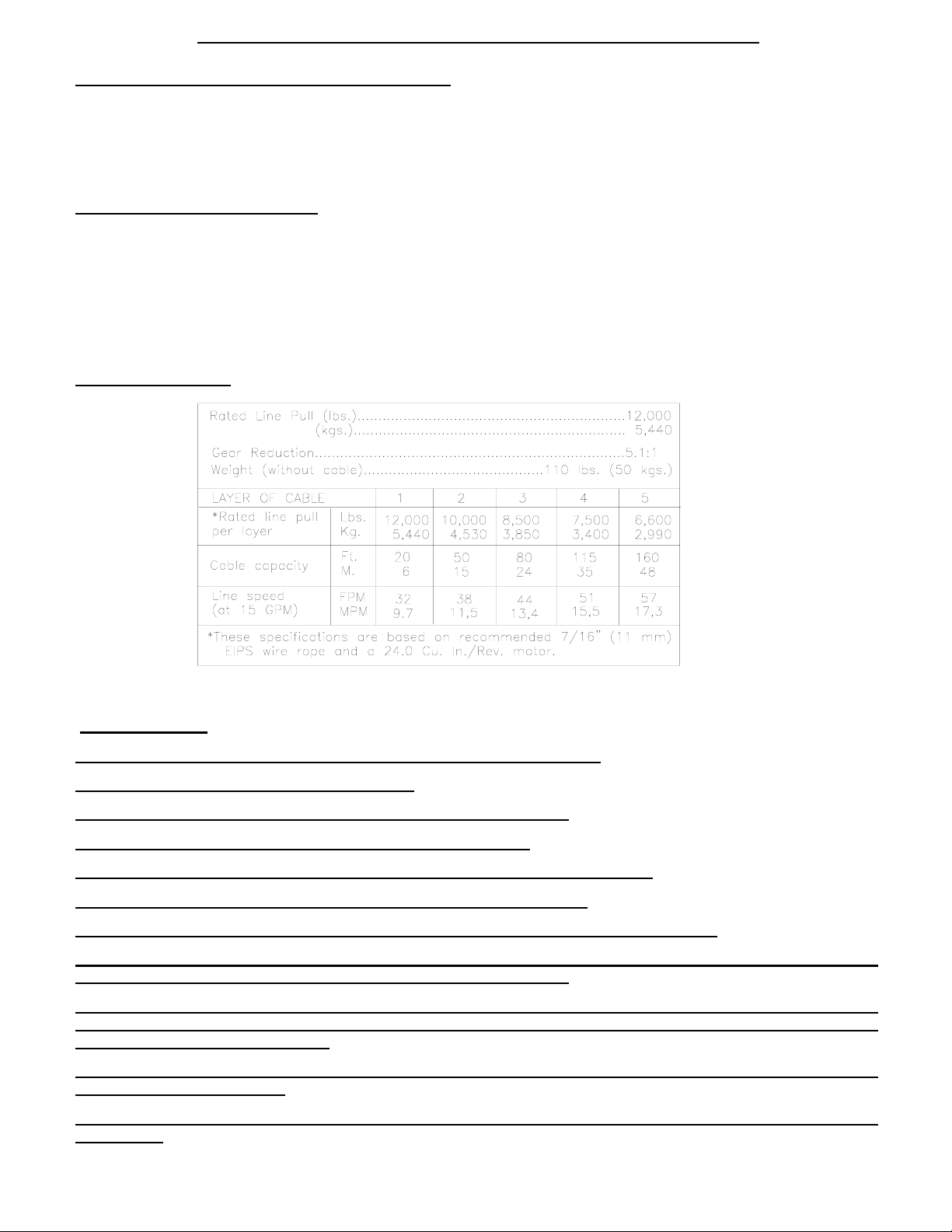
SPECIFICATIONS
*
NOTE: The rated line pulls shown are for the winch only. Consult the wire rope manufacturer for wire rope ratings.
WARNINGS:
CLUTCH MUST BE FULLY ENGAGED BEFORE STARTING THE WINCH.
DO NOT DISENGAGE CLUTCH UNDER LOAD.
DO NOT LEAVE CLUTCH ENGAGED WHEN WINCH IS NOT IN USE.
STAY OUT FROM UNDER AND AWAY FROM RAISED LOADS.
STAND CLEAR OF CABLE WHILE PULLING. DO NOT TRY TO GUIDE CABLE.
DO NOT EXCEED MAXIMUM LINE PULL RATINGS SHOWN IN TABLE.
DO NOT USE WINCH TO LIFT, SUPPORT, OR OTHERWISE TRANSPORT PERSONNEL.
A MINIMUM OF 5 WRAPS OF CABLE AROUND THE DRUM BARREL IS NECESSARY TO HOLD THE LOAD.
CABLE CLAMP (SETSCREW) IS NOT DESIGNED TO HOLD LOAD.
IN CAR CARRIER APPLICATIONS, AFTER PULLING VEHICLE ON CARRIER, BE SURE TO SECURE VEHICLE
TO CARRIER BED. DO NOT MAINTAIN LOAD ON WINCH CABLE WHILE TRANSPORTING VEHICLE. DO
NOT USE WINCH AS A TIE DOWN.
WHEN PULLING A HEAVY LOAD PLACE A BLANKET, JACKET, OR TARPAULIN OVER THE CABLE FIVE OR
SIX FEET FROM THE HOOK.
AVOID CONDITIONS WHERE LOAD SHIFTS OR JERKS OCCUR, AS THEY MAY INDICATE A DANGEROUS
SITUATION.
1
Page 4
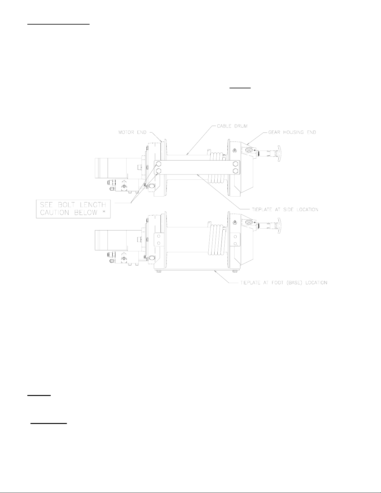
WINCH MOUNTING
ESSENTIAL MOUNTING INSTRUCTIONS TO MAINTAIN ALIGNMENT OF PLANETARY WINCH COMPONENTS
It is most important that this winch be mounted securely so that the three major sections (the motor end,
the cable drum and the gear-housing end) are properly aligned. Excessive bushing wear and difficulty in
freespooling are usually symptoms of misalignment.
In the as-installed condition, if the winch is mid mounted at least one tie plate must be attached to the
mounting feet at the bottom of the winch to maintain alignment. NOTE:
least one tie plate must remain mounted at mid point of winch to maintain alignment. It is always desirable
to use both tie plates in the final installed configuration.
If the winch is foot mounted, at
Angle Mounting Kit, #251006, is recommended for maximum ease in mounting the winch. The
angle kit will allow the winch to be mounted in upright or midmount applications and will meet the
criteria of serving as a solid and true mounting surface.
When mounting the winch with other than the recommended Ramsey Angle Kit, the mounting hole
patterns described on page 14 must be used. The mounting surface must be flat within .015 inch
and sufficiently stiff to resist flexing. If a steel plate is used for foot mounting it should be .750
inch thick. For this mounting application eight (8) 1/2-13NC x 1-1/2 Lg. Gr. 5 capscrews with
lockwashers will be needed to mount winch. Capscrews should be torqued to 85 ft. lb. (115 Nm.).
NOTE: If angles or a steel plate are used in mounting winch, tie plates provided with winch are to
be attached to the remaining mounting pads, whether they be side or foot.
*CAUTION:
If longer bolts (minimum Grade 5) are substituted to mount winch or to mount a roller
guide at the side mount pads, bolt length must be such as to allow a maximum of .56 inch thread
length engagement in the tapped holes in sides of each end bearing. Refer to page 13. Use of
excessive length bolts will not allow tie plate to tighten down properly. Torque bolts to 55 ft. lbs. (75
Nm).
2
Page 5
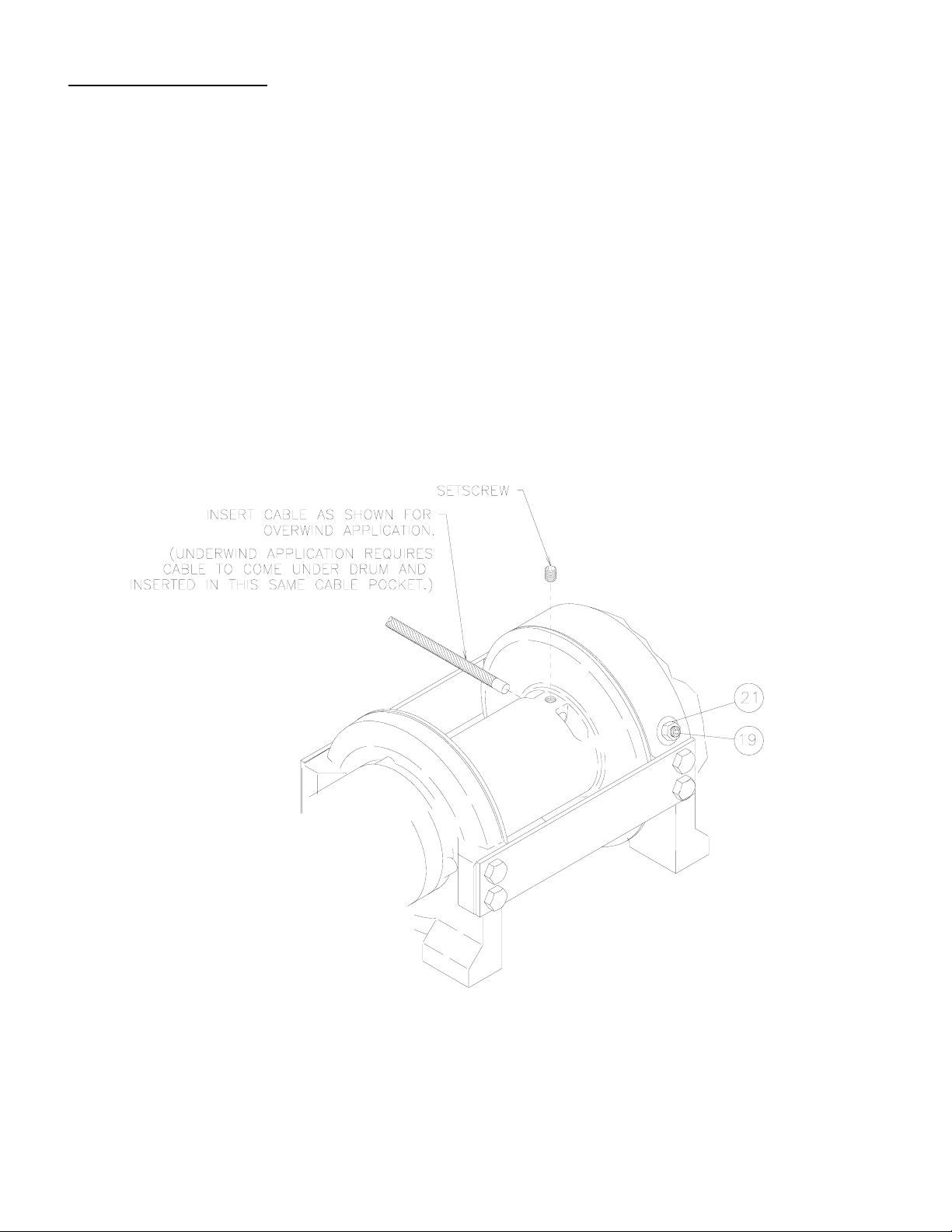
CABLE INSTALLATION
1. Unwind cable by rolling it out along the ground to prevent kinking. Securely wrap end of cable,
opposite hook, with plastic or similar tape to prevent fraying.
2. Place taped end of cable into hole in cable drum, as shown below. Use 3/8-16NC x 1/2 lg. Hx.
Soc. drive setscrew (part of 234171 drum assembly) to secure cable to drum.
3. Carefully run winch in the "reel-in" direction. Keeping tension on end of cable, spool all the
cable onto the cable drum, taking care to form neatly wrapped layers.
After installing cable, check freespool operation. Disengage clutch and pull on cable at a walking
speed. If cable "birdnests", loosen jam nut (item #21) and turn nylon screw (item #19) clockwise to
increase drag on drum. If cable pull is excessive loosen nylon setscrew by turning counterclockwise.
Tighten jam nut when proper setting is obtained.
CAUTION: Over-tightening of jam nut may strip nylon setscrew.
3
Page 6
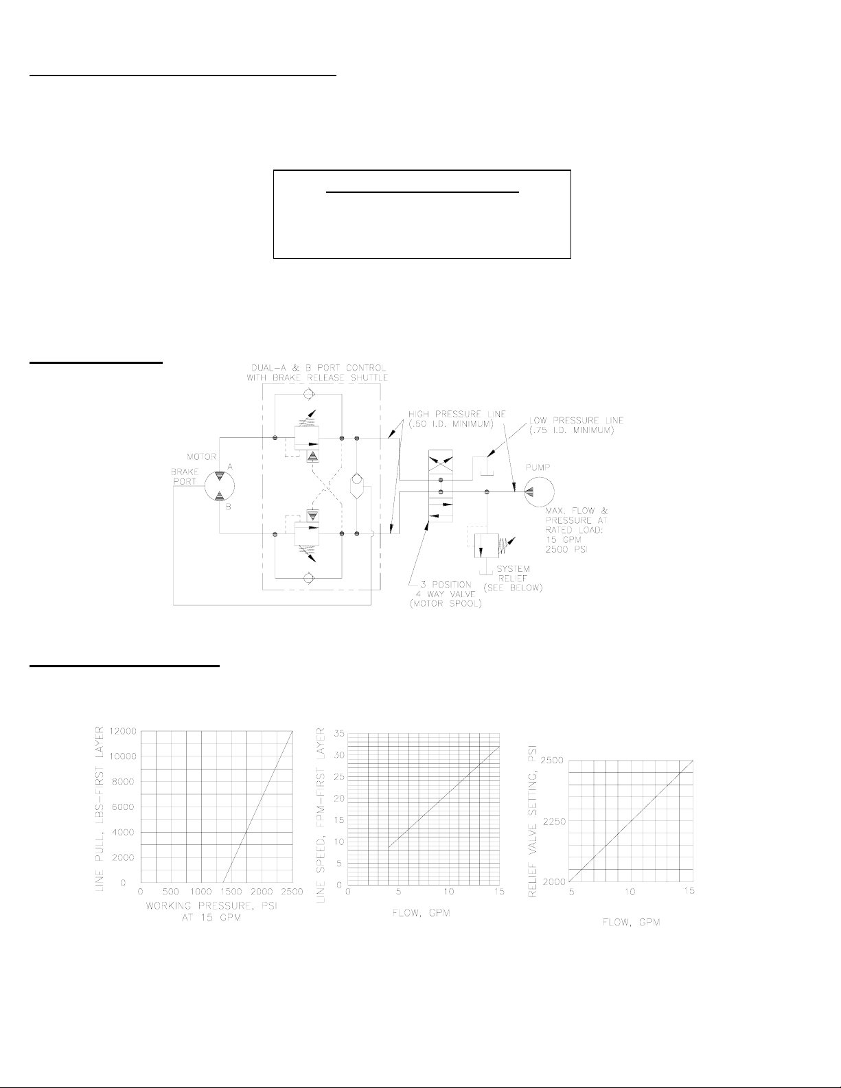
HYDRAULIC SYSTEM REQUIREMENTS
Refer to the performance charts below to properly match your hydraulic system to the winch performance. The charts
consist of: (1) first layer line pull (LB) vs. working pressure (PSI), (2) first layer line speed (FPM) vs. flow (GPM), and
(3) relief valve setting (PSI) vs. flow (GPM). A motor spool directional control valve is required.
SYSTEM REQUIREMENTS:
2500 PSI RELIEF VALVE SETTING*
15 GPM FLOW RATE**
10 MICRON NOMINAL FILTRATION
*CAUTION: DO NOT EXCEED 20 G.P.M. IF EXCEEDED, MOTOR AND WINCH MAY BE DAMAGED
TYPICAL LAYOUT
PERFORMANCE CHARTS
PERFORMANCE WITH 24.0 CU. IN. HYDRAULIC MOTOR
4
Page 7

OPERATION
The best way to get acquainted with how your winch operates is to make test runs before you
actually use it. Plan your test in advance. Remember, you hear your winch, as well as see it
operate. Get to recognize the sounds of a light steady pull, a heavy pull, and sounds caused by load
jerking or shifting. Avoid conditions where load shifts or jerks occur, as they may indicate a dangerous
situation.
The uneven spooling of cable, while pulling a load, is not a problem, unless there is a cable pileup on
one end of drum. If this happens, reverse the winch to relieve the load and move your anchor point
further to the center of the vehicle. After the job is done you can unspool and rewind for a neat lay of
the cable.
When pulling a heavy load place a blanket, jacket or tarpaulin over the cable about five or six feet
behind the hook. In the event of a broken cable, this will slow the snap back of the cable and could
prevent serious injury.
The winch clutch allows rapid unspooling of the cable from the cable drum for hooking onto the load.
The clutch is operated by the clutch shifter lever or air shifter.
WARNING: DO NOT DISENGAGE CLUTCH UNDER LOAD.
MANUAL CLUTCH SHIFTER (Refer to page 13)
TO DISENGAGE CLUTCH: Run the winch in the reverse (reel out) direction until load is off the cable.
Pull handle out and rotate 90o. With handle in the "DISENGAGED" position, cable may now be freespooled from drum.
TO ENGAGE CLUTCH: Pull handle out, rotate 90o and release handle. Run the winch in reverse until
the clutch handle snaps fully into the "ENGAGED" position. DO NOT attempt to pull a load unless the
handle is fully at the "ENGAGED" position.
AIR CYLINDER CLUTCH SHIFTER (Refer to page 14)
TO DISENGAGE CLUTCH: Run the winch in the reverse (reel out) direction until load is off the cable.
Apply air pressure to the .125-27 NPT port: 80 PSI (min.) 150 PSI (max.). CAUTION: Pressure must
not exceed 150 PSI.
TO ENGAGE CLUTCH: Remove air pressure from the cylinder (a return spring engages the plunger).
Run winch in reverse until the clutch engagement indicator light (green light) is lit. DO NOT attempt to
pull a load unless the green light is lit. To connect light to the vehicle electrical system refer to the
Electrical Schematic on page 14.
MAINTENANCE
1. Inspect the cable for damage and lubricate frequently. If the cable becomes frayed with broken
strands, replace immediately.
2. Check that the clutch is fully engaging. See OPERATION instructions, above, for the appropriate
clutch shifter. FOR MANUAL CLUTCH ONLY: Monthly disengage clutch, put several drops of oil on
the shaft and work clutch IN and OUT several times to lubricate inside of clutch cylinder.
3. Check to see that drum cable does not overrun (birdnest) when freespooling. Refer to page 3.
4. Replace drum bushings and seals when seals begin to seep grease. Refer to OVERHAUL
INSTRUCTIONS, page 7. Add additional lubricant, Mobilith SHC 007, to gears if required.
5
Page 8

TROUBLE SHOOTING GUIDE
CONDITIONS POSSIBLE CAUSE CORRECTION / ACTION
DRUM WILL NOT ROTATE Brake damaged. Inspect and replace brake.
AT NO LOAD
Gears damaged. Inspect and replace damaged gears.
Brake not releasing See section below.
DRUM WILL NOT ROTATE Load greater than rated Refer to Specifications pg.1
UNDER LOAD capacity of winch. for line pull rating.
Low hydraulic system Check pressure. Refer to HYDRAULIC
pressure. SYSTEMS performance charts pg. 4.
WINCH RUNS TOO SLOW Low hydraulic system flow rate. Check flow rate. Refer to
HYDRAULIC SYSTEMS flow chart page 4.
Motor worn out. Replace motor.
DRUM WILL NOT Clutch not disengaged. Check clutch shifter. Refer to page 5.
FREESPOOL Check ADJUSTMENT. Refer to page 10.
BRAKE WILL NOT RELEASE Brake damaged. Inspect and replace. Refer to page 8 & 11 for
overhaul.
CABLE BIRDNESTS WHEN Drag screw improperly Adjust nylon drag screw.
CLUTCH IS DISENGAGED adjusted. Refer to pg. 3.
EXCESSIVE NOISE Hydraulic system flow too high Check flow rate. Refer to HYDRAULIC
SYSTEMS flow chart pg. 4.
DRUM CHATTERS, Low hydraulic system flow. Check flow rate. Refer to HYDRAULIC
in "REEL IN" direction SYSTEMS flow chart pg. 4.
Low hydraulic system Check relief valve setting. Refer to
relief pressure setting. HYDRAULIC SYSTEMS pg. 4.
OIL SEEPAGE FROM Brake piston not sealing properly. Replace o-ring and back up rings on brake
BREATHER VENT OF piston. Refer to page 8 & 11.
BRAKE HOUSING
GREASE SEEPAGE FROM Grease applied to seals during NONE. Normal condition during the first
JOINTS IN MOTOR assembly by the motor manufacturer. few times the winch is operated.
6
Page 9

INSTRUCTIONS FOR OVERHAUL OF RAMSEY WINCH
MODEL RPH 12,000
DISASSEMBLY
Take note of mounting configuration for proper mounting of parts during re-assembly.
Disconnect tube (item #44) from elbows (item #24) on bottom of brake (item #6) and valve
(item #45). Remove motor (item #31) from brake housing (item #6) by unscrewing capscrews
(item #15). Tap motor lightly to disengage. Replace all gaskets, o-rings and seals with new
ones during re-assembly.
Remove coupling (item #23) from brake housing. Examine coupling for signs of wear, replace
if necessary. If necessary, remove valve (item #45) from motor by removing capscrews (item
#19) and lockwashers (item #49). If valve is removed make sure two square cross section orings remain seated in their counter bores in valve.
7
Page 10

Remove brake housing (item #6) from end bearing (item #4) by unscrewing (6) capscrews (item
#14) in a criss-cross pattern (2 turns each) until all capscrews are removed from brake housing.
Remove brake parts from brake housing. Examine brake discs (item #26) for signs of wear,
and replace if necessary. Examine o-rings (items #34 & #35) and backup rings (items #36 &
#37) for signs of wear. Remove o-rings and backup rings from grooves in brake piston (item
#3).
Remove and examine springs (items #42 & #43) for damage, replace if necessary.
Examine fitting (item #30) to assure that fittings are in proper working condition, replace if
necessary.
8
Page 11

Remove tie plates (item #9) from end bearings (items #4 & #5) by unscrewing capscrews (item
#16), as shown. Remove snap ring (item #41) and thrust washer (item #48) from shaft. Slide
motor end bearing (item #4) from drum (item #1) and drum from gear housing end bearing (item
#5).
Remove input shaft (item #8) and thrust washer (item #47) from end bearing. Inspect gear
teeth and splined end of shaft for signs of wear. If damaged, it will be necessary to replace
shaft.
Remove o-ring (item #32), bushing (item #12) from outside of motor end bearing (item #4),
remove o-ring (item #33), bearing (item #11) from inside of motor end bearing (item #4). Place
new, well oiled, o-ring (item #33) into groove inside of end bearing and press new bearing (item
#11) into end bearing. Press bushing (item #12) onto end bearing and dip o-ring (item #32) in
oil and seat into groove of end bearing.
Remove seal (item #40) from gear housing end bearing (item #5). Loosen nut (item #21) and
remove nylon setscrew (item #18) and remove ring gear (item #29) from gear housing end
bearing, if necessary. Remove bushing (item #13) and bearing (item #10) from gear housing
end bearing (item #5). Press new bushing (item #13) and bearing (item #10) into place in end
bearing. Install ring gear and nylon setscrew and nut. Ring gear must be fully seated in gear
housing end bearing (item #5) and slot in ring gear must NOT be aligned with clutch shifter hole.
Install new seal in gear housing end bearing, with sharp edge of seal outward.
9
Page 12

Generously apply grease (MOBILITH SHC 007) to teeth of ring gear (item #28), teeth of planet gears in
drum (item #1) and to bushing in gear housing end bearing (item #5). Apply a small amount of grease to
base of bushing on motor end bearing (item #4). Apply grease to teeth of gear and short end of shaft
(item #8). Place gear end of shaft through thrust washer (item #47) and into bearing in end bearing (item
#5). Place drum over shaft and rotate drum to engage planet gears with output gear on shaft and with
ring gear in end bearing.
Assemble end bearing (item #4) to drum assembly and use tie plates (item #9) and capscrews (item #16)
to hold both end bearings together. Tighten capscrews to 55 Ft. Lbs. (75 Nm.). Slide thrust washer (item
#48) over end of shaft and against end bearing (item #4). Place snap ring (item #41) into groove in
splined end of shaft.
If necessary, remove and replace appropriate shifter assembly (item #2 or #3), as follows:
MANUAL CLUTCH SHIFTER ASSEMBLY
Remove by loosening setscrew (item #18), jam nut and unscrewing clutch shifter. Be sure slot in ring
gear is not aligned with clutch shifter hole. Rotate drum, if necessary, to insure hole and slot are not
aligned. Reinstall clutch shifter with plunger, jam nut and handle positioned in cylinder housing, as
shown. Thread assembly (with handle engaged in cylinder slot) into the end bearing. Pull drum toward
the brake housing end bearing to remove play. Hold drum in the position and continue threading the
shifter assembly in until the gap between the end of the handle and cylinder is 7/16
handle is in the horizontal position, as shown below. NOTE: This gap will vary with drum endplay. With
the drum pulled against the gear housing, the gap should be 3/8 inch. Lightly tighten jam nut. Rotate
drum until handle snaps fully into the engaged position. Pull handle out and rotate 90o. Verify that drum
can be rotated freely (at least one full revolution) with clutch shifter at DISENGAGED position. Securely
tighten jam nut while holding the handle. Tighten setscrew securely. Re-check clutch operation as
described on page 5.
AIR CYLINDER SHIFTER ASSEMBLY
Remove by loosening setscrew (item #18), jam nut and unscrewing clutch shifter. To reinstall, thread air
cylinder into housing. Install one or two shims (item #45) under cylinder head, if needed, to orient air
cylinder port for pneumatic connections. Tighten setscrew. Refer to page 5 and check for proper
operation of the clutch.
BLOCKED CLUTCH
Insert plunger into gear housing bore so it engages into ring gear slot. Pull drum flange toward gear
housing and thread setscrew into housing until it bottoms out and drum starts to move. Back setscrew
out 1/2 turn and lock in place with jam nut.
+0
-1/16
inch and
10
Page 13

Set winch on gear housing end with motor end bearing (item #4) up. Insert (6) springs (item #42) into pockets of
motor end bearing (item #4), as shown, leaving top and bottom pockets empty. Install coupling (item #23) over
splined end of shaft (item #8). Put (4) brake pins (item #7) into (4) holes in motor end bearing. Install well-oiled o-
ring (items #34 & #35) and backup rings (items #36 & #37) into grooves in O.D. of piston (item #3). Place o-rings
into portions of grooves nearest to center of piston in both cases. See SECTION A-A below.
Piston (item #3), brake disc (item #26) and separator plates (item #39) must be clean and free of grease and oil.
Place piston over pins (item #7) and on top of springs (item #42). Place separator plates (item #39) and brake disc
alternately on top of piston, as shown below. Press larger diameter end of (4) springs (item #43) into pockets in
brake housing (item #6). Place gasket (item #27) on top of end bearing (item #4). Place brake housing over brake
parts with fitting ports downward toward mounting feet. Align mounting holes and force brake housing down onto
end bearing (item #4). Apply 271 Loc-tite to 6 capscrews (item #14) and finger tighten until flush with surface of
brake housing. Torque capscrews (2 turns each) in a criss-cross pattern until a torque of 30 ft. lbs., per capscrew, is
achieved.
11
Page 14

Place gasket (item #28) into position on mounting surface of motor (item #31). Slide motor shaft into coupling and
attach motor to brake housing (item #6). Use (2) capscrews (item #15) with lockwashers (item #22) and torque to 87
ft. lbs. (118 Nm) each. Securely connect tube (item #44) to elbows (item #24) in valve (item #45) and in bottom of
brake housing (item #6).
Apply at least 550 PSI hydraulic system pressure to release brake and verify that brake releases, by observing that
the winch drum rotates.
12
Page 15

MODEL RPH-12000
13
WITH MANUAL CLUTCH SHIFTER
Page 16

(TYP.)
(TYP.)
1.12
28,4
.56
*
14,2
(TYP.)
28,4
1.12
*
*
INDICATOR LIGHT
IS ENGAGED)
(ON WHEN CLUTCH
SCHEMATIC
ELECTRICAL
BUTT
CONNECTOR
57,2
CLUTCH)
*
2.25
4.56
115,8
.500-13UNC X .62" (15,7 MM) DEEP
TAPPED HOLE (TYP. 4 PLACES EACH
(TYP.)
9.12
231,6
TAPPED HOLE (TYP. 4 PLACES EACH
END BEARING)
.500-13UNC X .75" (19,1 MM) DEEP
ATTACH TO GROUND (16 GA.
SIDE OF WINCH)
E
D
G
*
T
A
I
G
L
N
E
N
E
H
H
C
*
C
T
W
L
U
256,8
10.11
56,1
2.21
5.05
128,4
ATTACH TO 12V DC (+)
ELECTRICAL SCHEMATIC)
ATTACH TO GROUND (SEE
(SEE ELECTRICAL SCHEMATIC)
3.81
96,8
2.21
RAMSEY WINCH CO
56,1
9.12
TULSA OK
231,6
4.62
117,3
.125-27NPT PORT
(CONNECT 80 TO 150 PSI **
PRESSURE LINE TO DISENGAGE
SWITCH
_
+
12V BATTERY
NOTE: LIGHT SHOULD BE "ON" WHEN CLUTCH IS
WIRE SUPPLIED BY CUSTOMER)
ENGAGED AND "OFF" WHEN CLUTCH IS DISENGAGED.
ATTACH TO PTO INDICATOR SWITCH TO
RECEIVE 12V DC WHEN PTO IS ENGAGED.
TRUE POSITION. RECOMMENDED MOUNTING HOLE DIAMETER IS .53" (13,5 MM).
*NOTE: THESE HOLE LOCATIONS MUST BE HELD WITHIN ±.03" (0,8 MM) OF
WINCH MOUNTING CAPSCREWS MUST MEET OR EXCEED SAE GRADE 5 SPECIFICATION
DIMENSIONS SHOWN ARE INCHES OVER MILLIMETERS
DIA.
.50
12,7
CABLE HOLE
29.58
751,3
STATIC LOAD
HOLDING BRAKE
16.25
412,7
6.12
FLANGE
DIA.
155,4
9.00
228,6
100,0
3.94
BARREL DIA.
9.75
DRUM
247,7
311,2
12.25
*
4.88
124,0
PRESSURE IN GIVES COUNTER-CLOCKWISE DRUM
A
5.53
140,5
1.75
ROTATION VIEWED FROM MOTOR END
44,5
ROTATION VIEWED FROM MOTOR END
PRESSURE IN GIVES CLOCKWISE DRUM
.88
22,4
O-RING PORT (TYP. 2 PLACES)
.875-14 SAE STRAIGHT THREAD
** CAUTION: PRESSURE MUST NOT EXCEED 150 PSI.
A-A
VIEW
WINCH
MOTOR CONTROL VALVE DETAIL
A
96,3
3.79
WITH AIR CYLINDER CLUTCH SHIFTER
MODEL RPH-12,000
14
Page 17

NOTES
15
Page 18

16
Page 19

PARTS LIST RPH 12,000 WITH MANUAL CLUTCH SHIFTER
ITEM QTY. PART NO. DESCRIPTION
1 1 234171 DRUM ASS'Y.
2 1 276052 SHIFTER ASS'Y.-MANUAL
3 1 306042 PISTON-BRAKE
4 1 338300 END BEARING-MOTOR
5 1 338301 END BEARING-GEAR HOUSING
6 1 338302 HOUSING-BRAKE
7 4 346045 PIN-BRAKE
8 1 357504 SHAFT-INPUT/SUN GEAR
9 2 395172 TIE PLATE
10 1 402120 BEARING-GEAR HSG.
11 1 402121 BEARING-MTR. END BEARING
12 1 412084 BUSHING-DRUM (MTR. END)
13 1 412085 BUSHING-DRUM (G.HSG. END)
14 6 414303 CAPSCREW-3/8-16NC X 2-1/2 LG. HX.HD., GR. 5 PLTD.
15 2 414948 CAPSCREW 1/2-13NC X 1-1/4 LG. SOC.HD.
16 8 414581 CAPSCREW 1/2-13NC X 3/4 LG. HX.HD. GR.5 PLTD.
17 2 414854 CAPSCREW 1/4-20NC X 1/2 LG. RD.HD. SLOT PLTD.
18 4 414159 CAPSCREW 5/16-18NC X 1-1/2 LG. HX HD. GR5 Z/P
19 1 414926 SETSCREW-3/8-16NC X 1 LG., SOCKET, NYLON
20 1 416016 SETSCREW-1/4-20NC X 1/4 LG., HX. SOC. HD.
21 1 418036 NUT 3/8-16NC HEX. JAM
22 2 418218 LOCKWASHER-1/2 ID MED. SECT.
23 1 431015 COUPLING-MOTOR
24 2 432018 FITTING-7/16 ELBOW
25 NOT USED
26 4 438022 DISC-BRAKE
27 1 442220 GASKET-BRAKE
28 1 442223 GASKET-MOTOR
29 1 444085 GEAR-RING
30 1 456038 FITTING-VENT
31 1 458090 MOTOR-HYDRAULIC
32 1 462046 O-RING (DRUM)
33 1 462056 O-RING
34 1 462057 O-RING
35 1 462058 O-RING
36 1 462059 O-RING BACKUP
37 1 462060 O-RING BACKUP
38 1 472052 PLUG
39 5 474111 PLATE-SEPARATOR
40 1 486080 SEAL-GEAR HSG.
41 1 490037 SNAP RING
42 6 494110 SPRING-BRAKE
43 4 494112 SPRING
44 1 509009 TUBE ASSEMBLY
45 1 516013 VALVE-MOTOR CONTROL
46 1 518037 THRUST WASHER
47 1 518047 THRUST WASHER
48 1 518052 THRUST WASHER
49 4 418163 LOCKWASHER – 5/16 MED SECT Z/P
17
Page 20

18
Page 21

PARTS LIST RPH 12,000 WITH AIR-CYLINDER CLUTCH SHIFTER
ITEM QTY. PART NO. DESCRIPTION
1 1 234171 DRUM ASS'Y.
2 1 236020 LIGHT ASSEMBLY
3 1 276053 SHIFTER ASS'Y.-AIR CYLINDER
4 1 306042 PISTON-BRAKE
5 1 312529 BRACKET-LIGHT
6 1 338300 END BEARING-MOTOR
7 1 338301 END BEARING-GEAR HOUSING
8 1 338302 HOUSING-BRAKE
9 4 346045 PIN-BRAKE
10 1 357504 SHAFT-INPUT/SUN GEAR
11 2 395172 TIE PLATE
12 1 402120 BEARING-GEAR HSG.
13 1 402121 BEARING-MTR. END BEARING
14 1 412084 BUSHING-DRUM (MTR. END)
15 1 412085 BUSHING-DRUM (G.HSG. END)
16 2 414036 CAPSCREW 1/4-20NC X 1/2 LG.
17 6 414303 CAPSCREW 3/8-16NC X 2-1/2 LG. HX.HD., GR. 5 PLTD.
18 2 414948 CAPSCREW 1/2-13NC X 1-1/4 LG. SOC.HD.
19 8 414581 CAPSCREW 1/2-13NC X 3/4 LG. HX.HD. GR.5 PLTD.
20 4 414159 CAPSCREW 5/16-18NC X 1-1/2 LG. HX. HD. GR 5 Z/P
21 1 414926 SETSCREW-3/8-16NC X 1 LG., SOCKET, NYLON
22 1 416016 SETSCREW-1/4-20NC X 1/4 LG., HX. SOC. HD.
23 1 418036 NUT 3/8-16NC HEX. JAM
24 2 418218 LOCKWASHER-1/2 ID MED. SECT.
25 1 431015 COUPLING-MOTOR
26 2 432018 FITTING-7/16 ELBOW
27 NOT USED
28 4 438022 DISC-BRAKE
29 1 442220 GASKET-BRAKE
30 1 442223 GASKET-MOTOR
31 1 444085 GEAR-RING
32 1 456038 FITTING-VENT
33 1 458090 MOTOR-HYDRAULIC
34 1 462046 O-RING (DRUM)
35 1 462056 O-RING
36 1 462057 O-RING
37 1 462058 O-RING
38 1 462059 O-RING BACKUP
39 1 462060 O-RING BACKUP
40 5 474111 PLATE-SEPARATOR
41 1 482013 BOOT
42 1 482045 BOOT
43 1 486080 SEAL-GEAR HSG.
44 2 488007 SHIM
45 1 490037 SNAP RING
46 6 494110 SPRING-BRAKE
47 4 494112 SPRING
48 1 504021 SWITCH
49 1 509009 TUBE ASSEMBLY
50 1 516013 VALVE-MOTOR CONTROL
51 1 518047 THRUST WASHER
52 1 518052 THRUST WASHER
53 4 418163 LOCKWASHER – 5/16 MED SECT Z/P
19
Page 22

20
Page 23

PARTS LIST RPH 12,000 WITH BLOCKED CLUTCH
ITEM QTY. PART NO. DESCRIPTION
1 1 234171 DRUM ASS'Y.
2 1 306042 PISTON-BRAKE
3 1 338300 END BEARING-MOTOR
4 1 338301 END BEARING-GEAR HOUSING
5 1 338302 HOUSING-BRAKE
6 4 346045 PIN-BRAKE
7 1 357504 SHAFT-INPUT/SUN GEAR
8 2 395172 TIE PLATE
9 1 402120 BEARING-GEAR HSG.
10 1 402121 BEARING-MTR. END BEARING
11 1 412084 BUSHING-DRUM (MTR. END)
12 1 412085 BUSHING-DRUM (G.HSG. END)
13 6 414303 CAPSCREW-3/8-16NC X 2-1/2 LG. HX.HD., GR. 5 PLTD.
14 2 414948 CAPSCREW 1/2-13NC X 1-1/4 LG. SOC.HD.
15 8 414581 CAPSCREW 1/2-13NC X 3/4 LG. HX.HD. GR.5 PLTD.
16 2 414854 CAPSCREW 1/4-20NC X 1/2 RD.HD. SLOT PLTD.
17 4 414159 CAPSCREW 5/16-18NC X 1-1/2 LG. HX. HD. GR 5 Z/P
18 1 414926 SETSCREW-3/8-16NC X 1 LG., SOCKET, NYLON
19 1 416016 SETSCREW-1/4-20NC X 1/4 LG., HX. SOC. HD.
20 1 416030 SETSCREW 5/8-18NF X 1 LG. HX.SOC.HD.
21 1 418036 NUT 3/8-16NC HEX. JAM
22 1 418088 NUT 5/8-18NF
23 2 418218 LOCKWASHER-1/2 ID MED. SECT.
24 1 426048 PLUNGER
25 1 431015 COUPLING-MOTOR
26 2 432018 FITTING-7/16 ELBOW
27 NOT USED
28 4 438022 DISC-BRAKE
29 1 442220 GASKET-BRAKE
30 1 442223 GASKET-MOTOR
31 1 444085 GEAR-RING
32 1 456038 FITTING-VENT
33 1 458090 MOTOR-HYDRAULIC
34 1 462046 O-RING (DRUM)
35 1 462056 O-RING
36 1 462057 O-RING
37 1 462058 O-RING
38 1 462059 O-RING BACKUP
39 1 462060 O-RING BACKUP
40 1 472052 PLUG
41 5 474111 PLATE-SEPARATOR
42 1 486080 SEAL-GEAR HSG.
43 1 490037 SNAP RING
44 6 494110 SPRING-BRAKE
45 4 494112 SPRING
46 1 509009 TUBE ASSEMBLY
47 1 516013 VALVE-MOTOR CONTROL
48 1 518037 THRUST WASHER
49 1 518047 THRUST WASHER
50 1 518052 THRUST WASHER
51 4 418163 LOCKWASHER – 5/16 MED SECT Z/P
21
Page 24

RAMSEY WINCH warrants each new RAMSEY Winch to be free from defects in material and workmanship
for a period of one (1) year from date of purchase.
The obligation under this warranty, statutory or otherwise, is limited to the replacement or repair at the
Manufacturer's factory, or at a point designated by the Manufacturer, of such part that shall appear to the
Manufacturer, upon inspection of such part, to have been defective in material or workmanship.
This warranty does not obligate RAMSEY WINCH to bear the cost of labor or transportation charges in
connection with the replacement or repair of defective parts, nor shall it apply to a product upon which
repair or alterations have been made, unless authorized by Manufacturer, or for equipment misused,
neglected or which has not been installed correctly.
RAMSEY WINCH shall in no event be liable for special or consequential damages. RAMSEY WINCH
makes no warranty in respect to accessories such as being subject to the warranties of their respective
manufacturers.
RAMSEY WINCH, whose policy is one of continuous improvement, reserves the right to improve its
products through changes in design or materials as it may deem desirable without being obligated to
incorporate such changes in products of prior manufacture.
If field service at the request of the Buyer is rendered and the fault is found not to be with RAMSEY
WINCH's product, the Buyer shall pay the time and expense to the field representative. Bills for service,
labor or other expenses that have been incurred by the Buyer without approval or authorization by
RAMSEY WINCH will not be accepted
See warranty card for details.
LIMITED WARRANTY
RAMSEY WINCH COMPANY
Post Office Box 581510 Tulsa, Oklahoma 74158-1510
Telephone: (918) 438-2760 FAX: (918) 438-6688
OM914002-0802-F
 Loading...