

Page 1
• Instant TR switching with 1 to 100
watts RF
• Compact and easy to install
• Operates on 12 - 14 VDC
• Matches Ramsey RF Amps and
Preamps
• Convenient size for mounting
within 1 1/2” PVC pipe - ideal for
mast mounted preamps
If you need a convenient way of bypassing or enabling an RF preamp or amplifier when
you key your rig, then this is the way to go! The RFS-1 can be configured to switch in or out
either a receive preamp or transmit power amp. Also has the ability to feed DC power
directly up the transmission line, making it great for mast mounted preamps and amps. A
very versatile transmit/receive switch for almost all RF switching purposes.
RFS1 —1
Kit No. RFS1
Page 2

INTRODUCTION TO THE RFS1
The RFS1 has been designed to work in conjunction with external RF preamps or RF power amplifiers to detect when the connected radio has been keyed, thereby bypassing a delicate preamp or
enabling a booster amplifier. It can be used in a range of RF powers ranging from 1 to 100 watts.
An inverter is supplied so that the relay can be opened when the radio is keyed to bypass a preamp without sending power to it. Without the inverter the relay is closed upon keying to allow a
booster amplifier to be in circuit.
RFS1 PARTS LIST
❒ 1 10ρF ceramic capacitor (marked 10 or 10K) (C3)
❒ 4 .01µF ceramic capacitors (marked .01, 10nF, or 103) (C1,C4,C5,C6)
❒ 1 100µF to 220µF electrolytic capacitor (C2)
❒ 4 10K Ω resistors [brown-black-orange] (R1,R2*,R3,R4)
❒ 1 1K Ω resistor [brown-black-red] (R2*)
❒ 1 100 Ω resistor [brown-black-brown] (R2*)
❒ 3 1N4148 diodes (D1,D2,D3)
❒ 3 2N3904 NPN transistors (Q1,Q2,Q3)
❒ 1 12 Volt DPDT relay (K1)
❒ 1 RFS circuit board
❒ 1 2.2mH coil, green body [red-red-gold-black] (L1)
*NOTE: To determine the value of R2 for your application, see Assembly step 4.
RFS1 —2
Page 3
RFS1 PC BOARD ASSEMBLY
As you can see there isn’t very much to do in this project, but be careful! Don’t rush and
improperly mount a part or leave long lead lengths on components. As all good RF technicians
and experimenters know, parts must be mounted flush to the PC board - not only for mechanical
strength and looks, but also to prevent radiation problems by long lead lengths acting as small
antennas. Just follow the assembly instructions carefully and take your time. Before you know it
you will be satisfied and have a working project!
RFS1 —3
Page 4

ASSEMBLY OF THE RFS1
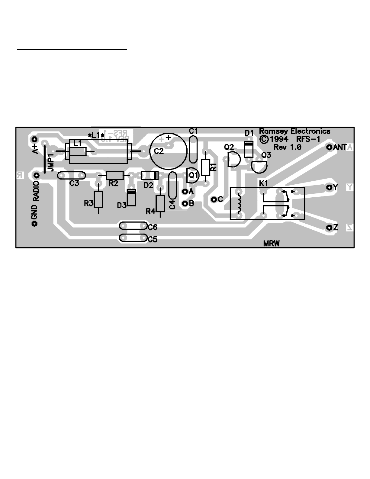
❒ 1. Orient the circuit board as shown in the parts layout diagram.
❒ 2. Install C3, the 10ρF ceramic capacitor (marked 10 or 10K).
❒ 3. Install R3, a 10K resistor [brown-black-orange].
❒ 4. Installing R2: First, determine the power output of your RF transceiver. This is, of
course, the power input to the RFS1. Then choose the appropriate value of R2 from
the table below (all three resistors have been supplied in this kit).
TABLE FOR R2
Power to RFS1 Value of R2
less than 10W
100Ω
10 to 30W
1KΩ
30 to 100W
❒ 5. Install D3, one of the 1N4148 type diodes. Be sure to note the cathode (banded)
10KΩ
end of the diode and its orientation on the layout diagram.
❒ 6. Install D2, another 1N4148 type diode. Again, observe correct orientation of the
banded end.
❒ 7. Install R4, a 10K resistor [brown-black-orange].
RFS1 —4
Page 5

❒ 8. Install C4, a .01µF ceramic capacitor (marked .01, 10nF, or 103).
❒ 9. Install C1, a .01µF ceramic capacitor (marked .01, 10nF or 103).
❒ 10. Install R1, a 10K resistor [brown-black-orange].
❒ 11. Install Q2, another 2N3904 type NPN transistor. Be sure to observe correct
orientation.
❒ 12. Install D1, the last 1N4148 type diode. Be sure to observe orientation of the banded
end.
❒ 13. Install Q3, the last transistor. Note again the orientation of the flat side.
❒ 14. Install K1, the DPDT RF relay. Note that this fits in only one way. Securely solder all
connections.
❒ 15. Install C5, a .01µF ceramic capacitor (marked .01, 10nF, or 103).
❒ 16. Install C6, another .01µF ceramic capacitor (marked .01, 10nF, or 103).
❒ 17. Install the 2.2µH coil (resistor shaped body, green color) [red-red-gold-black].
❒ 18. Install C2, the 100µF to 200µF electrolytic capacitor. Make sure the positive side of
the capacitor is mounted in the correct hole. In some cases only the negative lead is indi
cated with a stripe down the body of the capacitor. Make sure to orient the capacitor cor
rectly.
RFS1 —5
Page 6

Now is where we get to make a few decisions about the final assembly of the RFS1. You will need
to decide if it is to be used with an amplifier or with a preamp, and whether or not you want to feed
the DC power up the transmission line.
IF YOU’RE USING THE RFS1 TO SWITCH A RECEIVE PREAMP
❒ 19a. Install a jumper from holes B to C on the PC board. Use a piece of leftover
clipped-off component lead for this.
❒ b. Install Q1, a 2N3904 type transistor. Make sure its flat side has the same
orientation on the layout.
IF YOU’RE USING AN AMPLIFIER
❒ 19. Install a jumper from holes A to C on the PC board. Use a piece of left over
clipped-off component lead for this. Transistor Q1 is not used.
❒ 20. If you wish to send DC power up the transmission line to power the RFS1, install
JMP1 using a scrap piece of clipped-off component lead; if not then leave this jumper
out.
❒ 21. Now is a good time to check solder joints and part orientations for proper installation.
Check for cold solder joints or solder bridges.
RFS1 —6
Page 7

To Connect an Amplifier :
12-14 VDC
RF I N
RFS1
Rad io
A
B
To Connect a Preamplifier :
12-14 V DC
RF I N
RFS1
Rad io
A
B
Q1
C
C
Ant
Y
Z
Ant
Y
Z
RF OUT
Pre
Amp
RF OUT
AM P
Follow these simple diagrams
to connect your RFS1 to a
preamp or amplifier. Use coax
only and make sure the shield
conductor on the coax and
center conductor are as short
as possible when soldered
together.
RFS1 —7
Page 8

FREQUENCY CONCERNS OF L1
If you are planning on powering your RFS1 through the transmission line instead of the power
leads, notice that the value of L1 is going to be frequency dependent. Its purpose is to channel DC
from the transmission line into the circuit, but block the RF from coming into the power. A coil has a
certain resistance to RF called reactance. The larger the value of the coil, the more reactance it has
at a particular frequency. The less frequency there is, the less reactance there is. So if you are
working with HF, the coil provided will not be large enough in value.
What we are looking for is a coil with a reactance value larger than 1K ohms. To solve for this part
value the formula is a relatively simple plug and chug. Put the value for your coil in “L” and frequency in “F”. Remember to take the numerical values of your extensions into account such as
Mega = 1 million and micro = .000001. The formula is as follows:
X = 2 * 3.14 * L * F
For example, to find the reactance of the supplied coil in the two meter band, plug in the numbers
as follows:
2 * 3.14 * .0000022 * 146520000 = 2025 ohms
RFS1 —8
Page 9

So we find the coil has a reactance of about 2K ohms in the two meter band. Rearranging the
formula so we can find the value of a coil that has a reactance of 1K ohms at any frequency:
L = 1000 / (2 * 3.14 * F)
where F is the frequency you will be operating on. Use this value of coil for both at the power
source and as L1 in the RFS1. Note the diagram for jumper setting and parts placement for
feeding the power up the transmission line. The coil near the radio end of the coax should be
mounted as close as possible to the connections on the coax to prevent unwanted radiation.
Block diagram :
12 - 15VDC
Radio
.01uF
Choke
Value >= L1
Center conductor
Coax shield
RFS1 —9
R
JMP1
RFS-1
Page 10

Hook up of coil near radio :
From radio
.0 1 uF
Coil
To power
supply ground
To RFS-1
Heatshrink
or insu la te d w ire
To power
supply +V
OPERATING NOTES:
1. If the relay chatters, it is a sign of high SWR, which you will wish to resolve anyway by
antenna system or amplifier output adjustments.
2. If the relay action is “sloppy”, there is insufficient RF to drive the RFS1 circuit. This may
occur when using a “low power” HT setting.
3. The RFS1 will handle a range of powers depending on frequency. The following graph
depicts the approximate maximum power you should use to operate the RFS1 to prevent
overheating or other problems.
RFS1 —10
Page 11

100 W
50W
HF
2 m eter band
440M H z
INSTALLATION NOTES
If you haven’t noticed, the RFS1 has been designed in a way so that it fits well inside of 1 1/2 inch
PVC pipe. You can fit it into an existing enclosure, or use a piece of 1 1/2 inch PVC plus two
endcaps and some sealant to make a weather tight enclosure. Make sure all grounding
connections are as short as possible and all coax shields are grounded as well. Use miniature RG174 for best results.
Notice the four small holes around where each coax piece is to be mounted. The center conductor
of the coax is soldered into the labeled hole, and the four small holes are where you may use
pieces of scrap component lead to “strap down” the coax to the board. If you are planning on
mounting the RFS1 within a PVC pipe make sure and thread the coax pieces
RFS1 —11
Page 12

PC Board
PC Board
ANT
ANT
Y
Y
Z
Z
through the holes in the endcaps before soldering them to the board, especially if the wires are
very long! Read the next section on PVC mounting also.
Once you have strapped down the coax to the board with the jumper wire, solder the jumper wire
to the braid of the coax on top for a nice, mechanically solid solder joint. Don’t overheat when
you’re soldering; you don't want the braid to melt through to the center conductor and short out a
cable.
When you've got everything together, test out your wiring with a multimeter to make sure none of
the coax pieces are shorted, and double check all of your parts placements, especially if you are
feeding the power up the transmission line.
RFS1 —12
Page 13

HINTS FOR PVC MOUNTING
Locate the parts indicated in the diagram in your local plumbing supply or hardware store. Cut a 5
1/2 inch piece of PVC pipe and set it aside. Drill the appropriate holes in the endcaps to thread
the wires through, making sure the holes are only one size up in diameter from the wire diameter.
After threading the wire through, place the circuit board in the pipe and then solder the wires to
the board. If you forget to thread the wires, you’ll have a long process of pulling wire through the
holes. Don’t use PVC glue to glue the pipes together since you’ll never get them apart again.
Instead, use silicon sealant or something water-tight like wax to seal up the remaining holes.
When done, use pipe clamps to secure the RFS1 to a secure place.
Circuit board
Endcap
5 1/2" of 1 1/2"
diameter PVC
RFS1 —13
Endcap
Page 14

RFS1 —14
Page 15

Please read carefully BEFORE calling or writing in about your kit. All Ramsey kits will work if assembled properly. The very fact that your kit includes this new
manual is your assurance that a team of knowledgeable people have field-tested several "copies" of this kit straight from the Ramsey Inventory. If you need help,
please read through your manual carefully; all information required to properly build and test your kit is contained within the pages!
1. DEFECTIVE PARTS: It's always easy to blame a part for a problem in your kit. Before you conclude that a part may be bad, thoroughly check your work. All our
kit parts carry the Ramsey Electronics Warranty that they are free from defects for a full ninety (90) days from the date of purchase. Defective parts will be replaced
promptly at our expense. If you suspect any part to be defective, please mail it to our factory for testing and replacement. Please send only the defective part(s), not
the entire kit. The part(s) MUST be returned to us in suitable condition for testing. Please be aware that testing can usually determine if the part was truly defective
or damaged by assembly or usage. Don't be afraid of telling us that you 'blew-it', we're all human and in most cases, replacement parts are very reasonably priced.
2. MISSING PARTS: Before assuming a part value is incorrect, check the parts listing carefully to see if it is a critical value such as a specific coil or IC, or whether a
RANGE of values is suitable (such as "100 to 500 uF"). Often times, common sense will solve a mysterious missing part problem. If you're missing five 10K ohm
resistors and received five extra 1K resistors, you can pretty much be assured that the '1K ohm' resistors are actually the 'missing' 10 K parts. If you believe we
packed an incorrect part or omitted a part clearly indicated in your assembly manual as supplied with the basic kit by Ramsey, please write or call us with
information on the part you need and proof of kit purchase
3. FACTORY REPAIR OF ASSEMBLED KITS:
To qualify for Ramsey Electronics factory repair, kits MUST: 1) NOT be assembled with acid core solder or flux. 2) NOT be modified in any manner. 3) BE returned
in fully-assembled form, not partially assembled. 4) BE accompanied by the proper repair fee. No repair will be undertaken until we have received the MINIMUM
repair fee (1/2 hour labor) of $18.00, or authorization to charge it to your credit card account. 5) INCLUDE a description of the problem and legible return address.
DO NOT send a separate letter; include all correspondence with the unit. Please do not include your own hardware such as non-Ramsey cabinets, knobs, cables,
external battery packs and the like. Ramsey Electronics, Inc., reserves the right to refuse repair on ANY item in which we find excessive problems or damage due to
construction methods. To assist customers in such situations, Ramsey Electronics, Inc., reserves the right to solve their needs on a case-by-case basis.
The repair is $36.00 per hour, regardless of the cost of the kit. Please understand that our technicians are not volunteers and that set-up, testing, diagnosis, repair
and repacking and paperwork can take nearly an hour of paid employee time on even a simple kit. Of course, if we find that a part was defective in manufacture,
there will be no charge to repair your kit (But please realize that our technicians know the difference between a defective part and parts burned out or damaged
through improper use or assembly).
4. REFUNDS: You are given ten (10) days to examine our products. If you are not satisfied, you may return your unassembled kit with all the parts and instructions
and proof of purchase to the factory for a full refund. The return package should be packed securely. Insurance is recommended. Please do not cause needless
delays; read all information carefully.
The Ramsey Kit Warranty
RFS1 —15
Page 16

RAMSEY TRANSMITTER KITS
• FM10A FM Stereo Transmitter
• TV6 Television Transmitter
RAMSEY RECEIVER KITS
• FR1 FM Broadcast Receiver
• AR1 Aircraft Band Receiver
• SR2 Shortwave Receiver
• AA7 Active Antenna
• SC1 Shortwave Converter
RAMSEY HOBBY KITS
• SG7 Personal Speed Radar
• SS70A Speech Scrambler
• SP1 Speakerphone
• MD3 Microwave Motion Detector
• PH14 Peak Hold Meter
• TG1 DTMF Tone Grabber
RAMSEY AMATEUR RADIO KITS
• DDF1 Doppler Direction Finder
• HR Series HF All Mode Receivers
• QRP Series HF CW Transmitters
• CW7 CW Keyer
• CPO3 Code Practice Oscillator
• QRP Power Amplifiers
RAMSEY MINI-KITS
Many other kits are available for hobby, school, Scouts
and just plain FUN. New kits are always under
development. Write or call for our free Ramsey catalog.
Call or write for our
full line catalog!
TOTAL SOLDER POINTS
25
ESTIMATED ASSEMBLY
TIME
Beginner .............. 0.8 hrs
Intermediate ........ 0.5 hrs
Advanced ............. 0.3 hrs
REQUIRED TOOLS
• Soldering Iron Ramsey WLC100
• Thin Rosin Core Solder Ramsey RTS12
• Needle Nose Pliers Ramsey MPP4 or
RTS05
• Small Diagonal Cutters Ramsey RTS04
<OR> Technician’s Tool Kit TK405
ADDITIONAL SUGGESTED ITEMS
• Holder for PC Board/Parts Ramsey HH3
• Desoldering Braid Ramsey RTS08
• Digital Multimeter Ramsey M133
Published by Ramsey Electronics, Inc.
Copyright 1994 All rights reserved. Ramsey Electronics, Inc.
590 Fishers Station Drive Victor, NY 14564
Phone (585) 924-4560
Fax (585) 924-4555
RFS1 —16
www.ramseykits.com
 Loading...