

Page 1
REP 8000 24V MOTOR REPLACEMENT KIT
#251277
This kit replaces an existing 24V permanent magnet motor on a Ramsey REP 8000 winch with a new series wound
motor. Refer to the parts list on page 4 for a complete list of items in this kit.
Before you begin, disconnect the solenoid battery leads from the battery and remove winch from mounting. Place
winch on flat work surface.
1. Disconnect motor leads and remove solenoid from motor and set
solenoid aside.
2. Remove tie bar bolts and tie bars from winch and set aside.
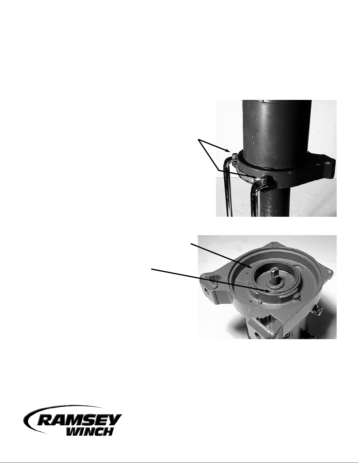
3. Lift motor end bearing from drum and discard. Install the
drum bushing (item #4) into the bore of the new motor
end bearing (item #1). Note: The drum bore has a castin key which the split in the drum bushing must straddle.
4. Apply grease (Moreplex NLGI 2 or equivalent) sparingly to
the I.D. of the drum bushing.
913401-0505-A
RAMSEY WINCH COMPANY
PO BOX 581510 - TULSA OK 74158-1510
www.ramsey.com
Page 2
5. Install new motor end assembly (item #1) on drum aligning
motor shaft with brake coupling.
6. Reinstall tie bars using (2) 1/4-20UNC x 3/4” capscrews
(item #6) on the motor end. Tighten securely.
Set winch aside.
7. Remove cover from solenoid assembly.
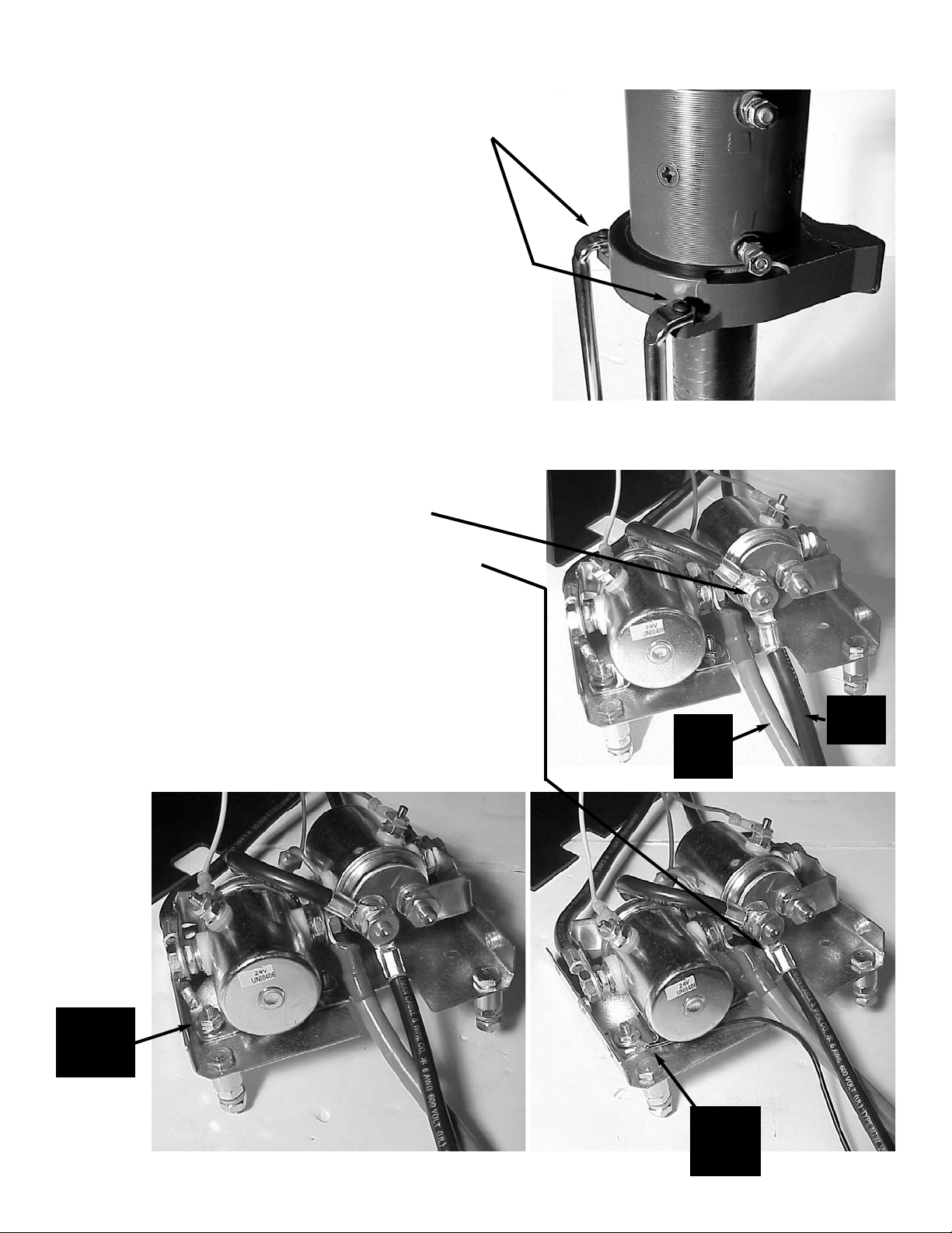
8. Remove battery ground wire and set aside. Install motor lead
wire assembly (item #2) to same terminal.
Bend terminal lug up so that it does not touch solenoid base.
9. Remove solenoid ground wire and discard (see below left).
10. Install new solenoid ground wire (item #3) using existing
hardware. Route wire out the same hole as the battery lead
(see below right).
2
Battery
Ground
Wire
Battery
+ (Pos)
Wire
(RED)
Existing
Solenoid
Ground
Wire
New
Solenoid
Ground
wire
Page 3

11. Label motor leads coming out of solenoid assembly
as shown:
12. Re-install cover on solenoid assembly.
13. Install boots (item #8) on existing motor leads.
14. Install battery ground wire (removed in step #8) and solenoid ground wire (item #3) to motor ground (on underside
of motor) using grounding bolt and lockwasher (items #5 &
7). Tighten securely.
Motor
Lead
“A”
Motor
Lead
“2”
Motor
Lead
“1”
Battery
+ (Pos)
Wire
(RED)
3
Page 4

ITEM NO. QUANTITY PART NO. DESCRIPTION
1 1 296591 REPLACEMENT MOTOR END BEARING ASSEMBLY, 24V
2 1 289115 MOTOR LEAD WIRE ASSEMBLY #6 GA 17” LONG
3 1 289208 SOLENOID GROUND WIRE ASSEMBLY #18 GA 12.5” LONG
4 1 412056 DRUM BUSHING
5 1 414370 BOLT 3/8-24NF X 1/2” LG HX HD GR5 Z/P
6 2 414823 CAPSCREW 1/4-20UNC X 3/4” LG HX SOC BUTTON HD
7 1 418177 LOCKWASHER 3/8 MED Z/P
8 2 482020 BOOT #6 GA
MOTOR REPLACEMNET KIT PARTS LIST
4
15. Connect motor leads to terminals on side of motor end bearing assembly as shown below:
16. Tighten nuts on terminals and slip boots over studs.
After you complete replacement of the motor, connect the battery leads to a battery and confirm that the winch operates in the IN and OUT directions.
Motor
Lead
“A”
Motor
Lead
“1”
Motor
Lead
“2”
 Loading...