

Page 1
Ramsey Winch Company
OWNER’S MANUAL Front
Mount Electric Winches
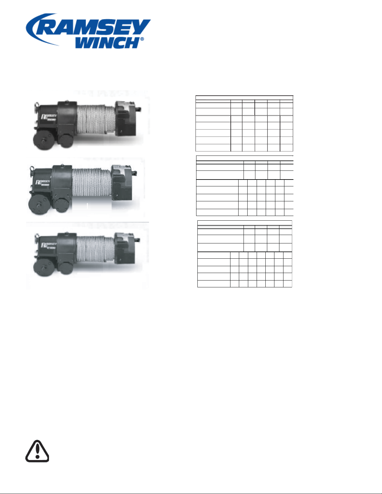
Model RE 8,000
Model RE 10,000
Model RE 12,000
Model RE 12,000X
RE8000
RE1000
RE12000
RATED LINE PULL PER LAYER (LBS)
CABLE CAPACITY PER LAYER (FT)*
RATED LINE PULL PER LAYER (LBS)
CABLE CAPACITY PER LAYER (FT)*
RATED LINE LBS
PULL PER LAYER KGS
CUMULATIVE CABLE (ft.)*
CAPACITY PER LAYER (M) *
(3/8" DIA. WIRE ROPE)
CUMULATIVE CABLE (ft.)*
CAPACITY PER LAYER (M) *
(3/8" DIA. WIRE ROPE)
LINE PULL (LBS)
FIRST LAYER (KGS)
12V-LINE SPEED FPM
FIRST LAYER MPM
AMP DRAW 12V
24V-LINE SPEED FPM
FIRST LAYER MPM
AMP DRAW 24V
LAYER OF CABLE
12V-LINE SPEED FPM
24V-LINE SPEED FPM
LAYER OF CABLE
12V-LINE SPEED FPM
24V-LINE SPEED FPM
LAYER OF CABLE
(KGS)
5/16 DIA. (M)*
LINE PULL (LBS)
(KGS)
MPM
AMP DRAW 12V
MPM
AMP DRAW 24V
3/8 DIA. (M)*
LINE PULL (LBS)
AMP DRAW 12V
AMP DRAW 24V
(KGS)
MPM
MPM
RE 12,000/12,000X
RE 8000
1
8,000
3,620
20
6
0
0
20
6.1
90
15
4.5
36
RE 10,000
(KGS)
RE 12,000
RE 12,000X
0
0
16
4.9
80
14
4.2
30
0
0
16
4.9
80
14
4.2
30
2,000
900
8.6
2.6
150
2.1
50
2,000
900
9.5
2.9
170
10,000
4,530
12,000
5,430
7
7.5
2.2
2
6,800
3,080
50
15
75
1
20
6
1
20
25
2,000
900
8.6
2.6
150
2.1
50
6
7
4,000
1,810
5.5
2.0
200
1.5
85
7
5
3
6,000
2,710
80
24
4,000
1,810
7
2.1
235
5.5
1.6
105
2
8,300
3,750
40
12
4,000
1,810
6.5
2.0 1.6
200
5
1.5
85
2
10,000
4,530
40
12
60
18
6,000
2,710
5.3
1.6 1.3
250
4
1.2
110
4
5,300
2,400
120
36
6,000
2,710
5.3
1.6
305
4
1.2
140 170
3
7,200
3,260
70
21
6,000
2,710
5.3
250
4
1.2
110
3
8,600
3,890
70
21
95
28
10,000
8,000
3,620
4.4
290
3.5
1
135
8,000
3,620
4.4
1.3
290
3.5
135
4,530
3.8
1.2
335
2.5
0.7
160
5
4,800
2,170
150
45
8,000
3,620
4.3
1.3
370
3
0.9
4
6,300
2,850
100
30
10,000
4,530
3.8
1.2
335
2.5
0.7
1
160
4
7,500
3,390
100
30
125
38
12,000
5,430
3.3
1
380
2
0.6
190
CONGRATULATIONS
You have purchased the fi nest winch available in its
service class. It features a strong worm and gear
drive to provide load-reversing protection. An exclusive semi-automatic RAM-LOK clutch disengages
for free spooling and is spring loaded for positive
engagement. It was designed and manufactured
to provide you with the utmost in utility. As with any
device that combines power and movement in
its use, there are dangers if improper1y used. At
the same time, there are easier and faster ways
for getting the job done if certain precautions are
taken fi rst. Please read this manual carefully. It
contains useful ideas in obtaining the most effi cient
operation from your Ramsey Winch and safety procedures you need to know before beginning use.
CAUTION: Read and understand this manual before installation and operation of
winch. See safety precautions.
When you follow our guidelines for operation your Ramsey Winch will give you many
years of satisfying service. Thank you for
choosing Ramsey. You will be glad you have
one working for you.
Please Note: Ramsey RE 8000, RE 10,000
and RE 12,000 Series winches are designed
for front mount vehicle use. The winches are
not designed for and should not be used in
industrial applications (car haulers/carriers,
wreckers, hoisting,etc.), and Ramsey does
not warrant them to be suitable for such use.
Ramsey makes a separate, complete line
of winches for industrial/commercial use.
Please contact the factory for further information.
Page 2

TABLE OF CONTENTS
Safety Precautions ............................ 1
Tips For Safe Operation ............................ 2
Techniques of Operation ............................ 3
Cable Installation ........................... 4
Operating Instructions ........................... 5
Electrical Connections and Operations ......... 6
Lubrication/ ......................... 6
Troubleshooting Guide ........................... 7
Winch Exploded Views and Parts List
RE 8,000 ............................ 8-9
RE 10,000 ............................ 10-11
RE 12,000/12,000X ............................ 12-13
Solenoid Parts LisVFairleads & Switch ......... 14
Accessory Information ........................... 15
Warranty ........................... Back Cover
Page 3

SAFETY PRECAUTIONS
Safety Precautions To Guard Against Possible Injury.....
A minimum of five wraps of cable around the drum barrel is necessary to hold
the rated load. Cable clamp is not designed to hold the load.
A. Keep yourself and others a safe dis-
tance to the side of the cable when
pulling under load.
B. Do not step over a cable, or near a
cable under load.
C. Use supplied hook strap when han-
dling hook for spooling wire rope.
D. Do not move the vehicle to pull a load
on the winch cable. This could result
in cable breakage and/or winch damage.
E. Use a heavy rag or gloves to protect
hands from burrs when handling winch
cable.
F. Apply blocks to wheels when vehicle
is on an incline.
G. Winch clutch should be disengaged
when winch is not in use and fully
engaged when in use.
H. Modification, alteration, or deviation
to the winch should only be made by
Ramsey Winch Company.
I. Keep the duration of your pulls
as short as possible. If the motor
becomes uncomfortably hot to the
touch, stop and let it cool for a few
minutes. Do not pull more than one
minute at or near the rated load. Do
not maintain power to the winch if the
motor stalls. Electric winches are for
intermittent usage and should not be
used in constant duty applications.
J. Disconnect the remote control
switch from the winch when not in
use. A Ramsey Part No. 282053
battery disconnect switch in your
vehicle is recommended.
K. Do Not use winch in hoisting appli-
cations due to required hoist safety
factors and features.
L. Do not exceed maximum line pull
ratings shown in tables. Shock
loads must not exceed these ratings.
M. To respool correctly, it is necessary
to keep a slight load on the cable.
This is accomplished by (wearing
gloves) holding the cable with one
hand and the remote control with
the other, starting as far back and
in the center as you can, walking up keeping load on the cable
as the winch is powered in. Do
not allow the cable to slip through
your hand and do not approach
the winch too closely. Turn off the
winch and repeat the procedure
until all the cable except a few feet
is in. Disconnect the remote control switch and finish spooling in
cable by rotating the drum by hand
with clutch disengaged. On hidden winches, spool in cable under
power using supplied hook strap.
1
Page 4

SAFE OPERATION TIPS
Tips for Safe Operation
Do not underestimate the potential danger in
winching operations. Neither should you fear
them. Do learn the basic dangers and avoid
them.
The uneven spooling of cable, while pulling a
load, is not a problem, unless there is a cable
pileup on one end of drum. If this happens,
reverse the winch to relieve the load and
move your anchor point further to the center of the vehicle. After the job is done you
can unspool and rewind for a neat lay of the
cable.
Store the remote control switch inside your
vehicle where it will not become damaged.
Inspect it before you plug it in.
When ready to begin spooling in, plug in
remote control switch with clutch disengaged.
Do not engage clutch with motor running.
Never connect the hook back to the cable.
This causes cable damage. Always use a
sling or chain of suitable strength as shown in
the illustration, page 3.
Observe your winch while winching, if possible, while standing at a safe distance. If you
use vehicle drive to assist, stop and get out
every few feet to assure the cable is not piling
up in one corner. Jamming cable can break
your winch.
Do not attach tow hooks to winch mounting apparatus. They must attach to vehicle
frame.
When double lining during stationary winching, the winch hook should be attached to the
chassis of the vehicle.
Since the greatest pulling power is
achieved on the innermost layer of
your winch, it is desirable to pull off as
much line as you can for heavy pulls.
Remember, a minimum of 5 wraps of
cable around the drum barrel is necessary to hold the rated load.
If this is not practical, use a snatch
block and double line arrangement as
shown in the illustration, page 3. Neat,
tight spooling avoids cable binding.
Cable binding occurs when a cable
under load pulls down into the layer
below, becoming pinched between two
other wraps of cable. If this happens,
alternately power the winch in and out
a few inches. Do not attempt to work a
bound cable under load; free by hand.
Since the greatest pulling power is
achieved on the innermost layer of your
winch, it is desirable to pull off as much line
as you can for heavy pulls. Remember, a
minimum of 5 wraps of cable around the
drum barrel is necessary to hold the rated
load.
If this is not practical, use a snatch block
and double line arrangement as shown in
the illustration, page 3. Neat, tight spooling
avoids cable binding. Cable binding occurs
when a cable under load pulls down into
the layer below, becoming pinched between
two other wraps of cable. If this happens,
alternately power the winch in and out
a few inches. Do not attempt to work a
bound cable under load; free by hand.
2
Page 5
TECHNIQUES OF OPERATION
Techniques of Operation
The best way to get acquainted with how your
winch operates is to make a few test runs
before you actually need to use it. Plan your
test in advance. Remember
winch as well as see it operate. Get to recognize
the sound of a light steady pull, a heavy pull, and
sounds caused by load jerking or shifting. Soon
you will gain confidence in operating your winch
and its use will become second nature with you.
you hear your
Your winch will not only pull you up or ease
you down a steep grade, it will also pull another
vehicle or a load while your vehicle is anchored in
a stationary position. The following illustrations
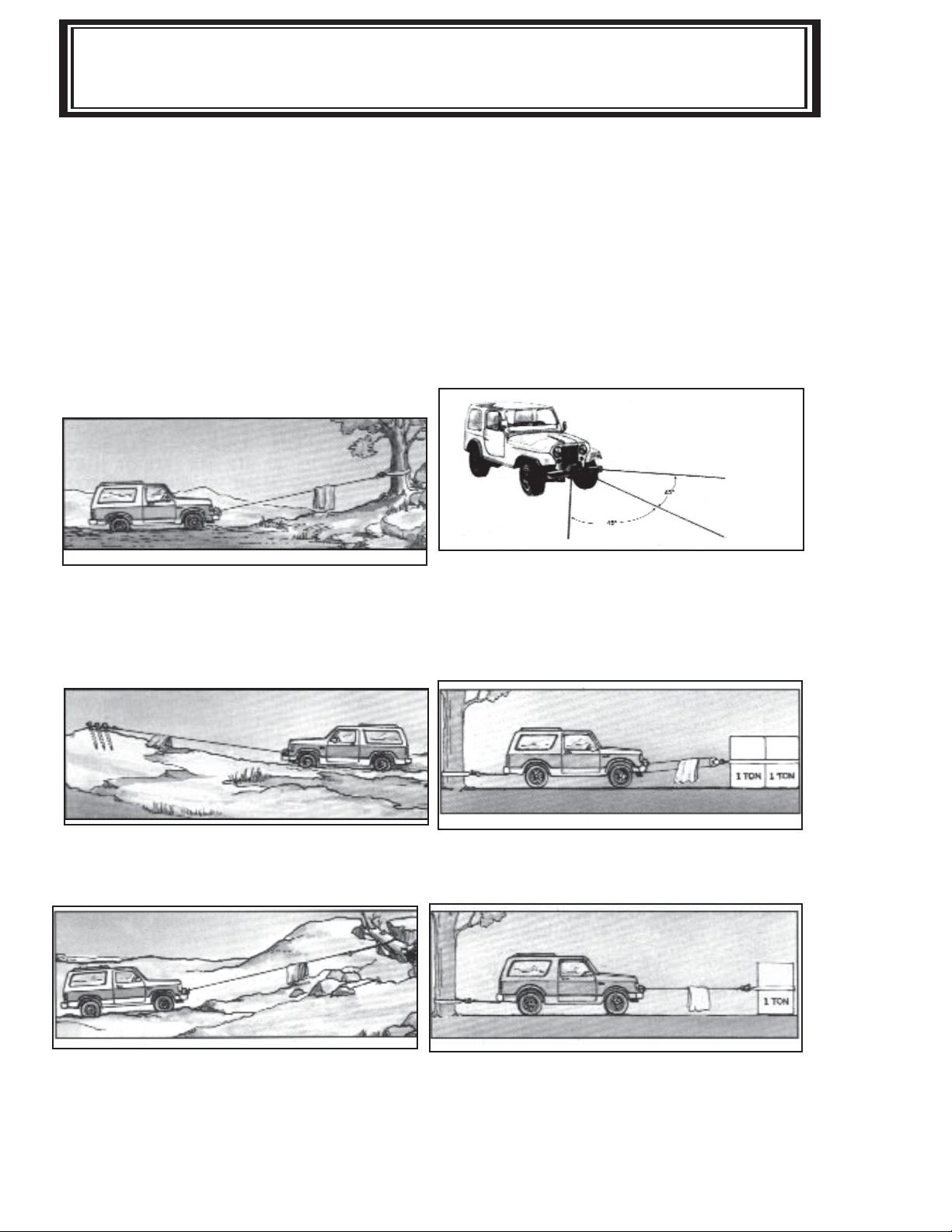
show a few basic winching techniques.
For basic self recovery, anchor to a tree or heavy rock. When
anchoring to a tree, always use a tree trunk protector.
Stakes driven in solid earth and chained together make a good
anchor point for self-recovery when no solid anchor point is
available.
Winches equipped with cable guide fairleads can pull from
several directions. Pull from an angle only to straighten up
the vehicle-otherwise you can damage structural members or
other parts of your vehicle and cause excess cable buildup on
one end of the winch drum.
To double the pull, use 2-part line with snatch block and tie
off to chassis. Take out of gear.
For a solid anchor, bury a log with earth or sand or place it in
a deep ravine
3
For a direct pull of 2,000 lbs., hitch truck to a tree or solid
anchor, and take out of gear.
Page 6
WINCH INSTALLATION / ELECTRICAL CONNECTIONS
Installation
Winches shown in this owner’s manual are
solely and exclusively designed for vehicle
mounted, non-industrial applications. Use
in other applications will void warranty. It is
recommended that Ramsey Mounting Kits
be used to mount the winch. They are designed to align the winch and distribute up to
the full rated load correctly to avoid possible
damage to the winch or vehicle.
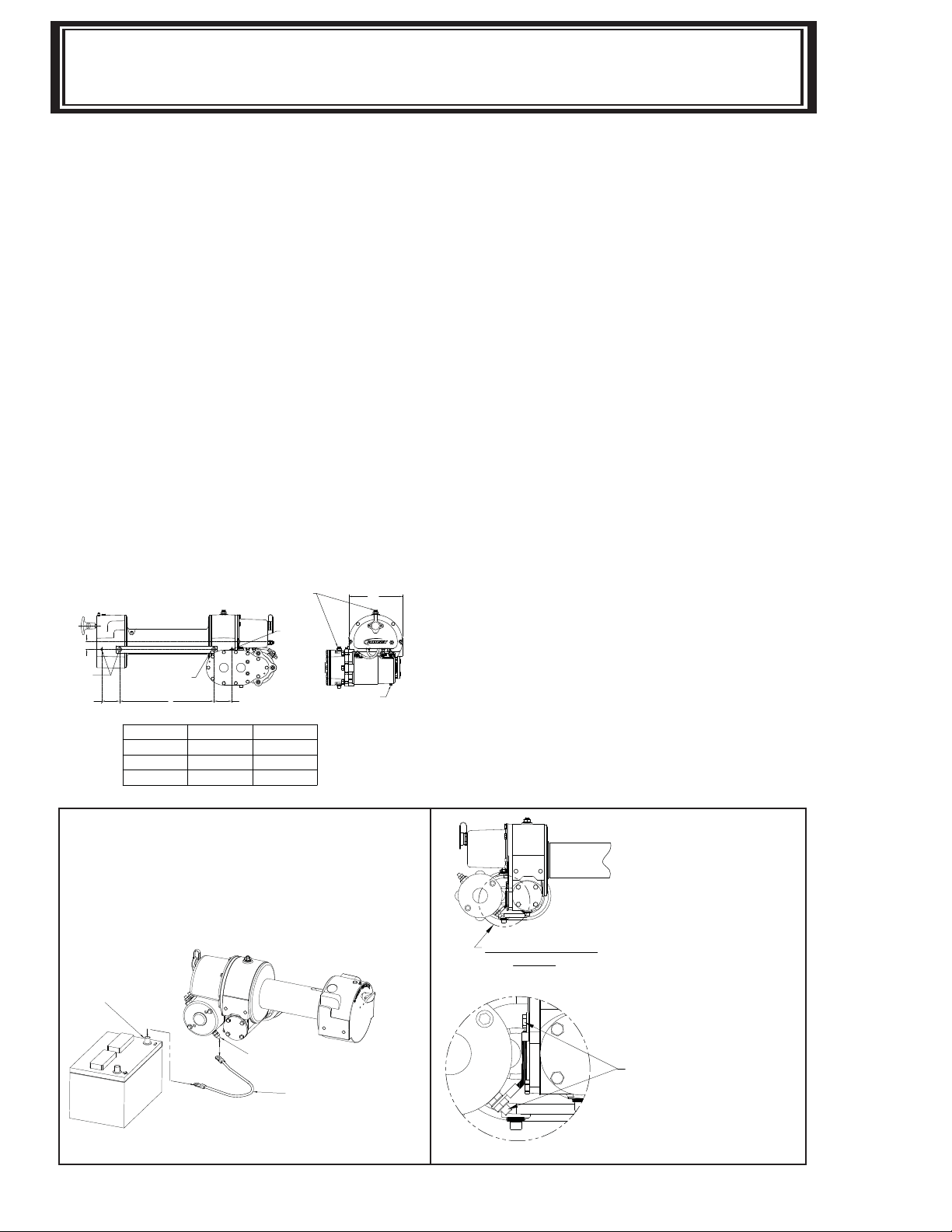
NOTE: If Ramsey Kits are not used, the
winch must be mounted to angles (3/8”
x 2 1/2” x 3” min) or in a frame with both
sides of the clutch housing and gear
housing bolted to the angles or frame.
See diagram below for recommended
mounting dimensions.
Note various thread
depths of mounting holes and use
correspondingly different bolt lengths for
proper mounting.
REMOVE RUBBER COVER FROM
RELIEF FITTINGS BEFORE PUTTING
WINCH INTO USE.
.38-16UNC X .50"
DEEP THREADS
(EACH SIDE)
2.50
63,5
GROUND CABLE FROM MOTOR ISOLATED
GROUND TERMINAL TO NEGATIVE
BATTERY TERMINAL.
MM ± .4
257.2
333.3
.38-16UNC X .75"
DEEP THREADS
(EACH SIDE)
1.12
.38-16UNC X 1"
DEEP THREADS
2.50
63,5
(EACH SIDE)
A
DIMENSIONS SHOWN ARE INCHES OVER MILLIMETERS
Model
RE 8/10/12
RE 12,000X
"A" Dimension
In. ± .15
10.12
13.12
7.44
188,9
Substitution of attaching hardware items
(bolts, nuts, or washers) different from
those supplied with your winch mounting
kit can lead to failure causing damage or
serious injury. Use a socket head mounting
bolt on side with Spur Gear Housing (see
diagram) to prevent clearance prob lems.
Use SAE grade 5 bolts or better.
Electrical Connections and
Operations
For normal self recovery work, your existing
electrical sys tem is adequate. Your battery must be kept in good condition. Afully
charged battery and proper connections are
essential. Run the vehicle engine during
winching oper ation to keep battery charged.
Connect red cable from stud on plastic
solenoid cover on winch to positive battery
terminal. Important: Hold inner nut with
end wrench while tightening outer nut.
Connect black cable from negative battery
terminal to the motor isolated ground terminal. In applications where the chassis is
non-grounded, a jumper wire (#440315) will
be required between the winch and the motor isolated ground terminal. (See illustration below.)
NEGATIVE BATTERY POST
WINCH WILL NOT OPERATE UNLESS
GROUND CABLE IS INSTALLED FROM THE
ISOLATED GROUND TERMINAL TO THE
NEGATIVE BATTERY POST.
(SEE DIAGRAM BELOW)
ISOLATED GROUND
TERMINAL
GROUND CABLE
SEE ILLUSTRATION
BELOW
JUMPER CABLE (#440315) MUST BE
INSTALLED ON WINCH FROM MOTOR
ISOLATED GROUND STUD TO GEAR
HOUSING COVER BOLT AS SHOWN
FOR NON GROUNDED CHASSIS
APPLICATIONS.
4
Page 7

CABLE INSTALLATION / OPERATING / MAINTENANCE
This ground is required to insure a suffi cient ground to operate the solenoid
assembly (see diagram below). A good
electrical ground is required for proper
performance. The remote control switch is
water proof and has push but ton stations
on either side. It is designed this way to
prevent quick winch reversals which lead to
solenoid failure. Make sure the winch motor has stopped fully before revers ing.
When fi rst setting up your winch, follow
the directions for inserting the proper “IN”
or “OUT” label in the thumb button. The
switch is also color coded to aid you in not
having to guess at the direction your winch
will run.
Cable Installation
1 Unwind cable by rolling it out along the
ground to pre vent kinking. Securely
wrap end of cable, opposite hook, with
plastic or similar tape to prevent fray ing.
2. Insert the end of the cable, opposite
hook end, under drum and into the
7/16” dia. hole in drum barrel. Secure
cable to drum barrel, using setscrew
furnished with winch. Tighten setscrew
securely.
3. Carefully run winch in the “reel-in” di rection. Keeping tension on end of
cable, spool all the cable onto drum,
taking care to form neatly wrapped lay ers.
Inspect the cable frequently. If the cable
becomes frayed with broken strands, replace immediately. Cable and hook assemblies may be purchased from a Ramsey
distributor.
The RAM-LOK™ semi-automatic clutch
provides free spooling and clutch engagement with the cable drum. With the clutch
disengaged, the cable can be pulled off the
drum by hand. For winching in the load, the
clutch must be fully engaged with the drum.
To disengage the clutch, run the winch in the
reverse (“reel out”) direction until the load
is off the cable and the cable drum stops
turning. Pull outward on the clutch handle,
rotate it counterclockwise 90° and release.
The clutch is now locked out and the cable
may be pulled by hand. (NOTE: if the clutch
handle can not be pulled out, again run the
winch momentarily in reverse to relieve pressure on the clutch jaws.)
WARNING: DO NOT ATTEMPT TO
DISENGAGE THE CABLE DRUM
WHEN THERE IS A LOAD ON THE
CABLE.
Operating Instructions
To engage the clutch, pull outward on the
handle, rotate it clockwise 90° and release.
Run the winch in reverse until the clutch
handle snaps fully in or until the cable drum
starts turning. At this point make sure the
clutch handle is all the way in. The plastic
plug in top of clutch housing may be removed, for inspection of clutch to assure
total engage ment. After the clutch is fully
engaged, the winch is ready for winching in
the cable.
Maintenance
Check monthly the action of the sliding
clutch, making sure it is fully engaging and
disengaging with the cable drum. With the
clutch in the engaged position, remove the
plastic plug in top of the housing and observe
if the clutch is fully engaging. If clutch is not
fully engaging, inspect the clutch shifter assembly parts, check for damage or excessive
wear and replace as necessary.
Observe the jaws on both the clutch and
cable drum, checking for rounding of the
driving faces. If rounding has occurred they
should be replaced immediately.
5
Page 8

MAINTENANCE (continued)
Spool the cable properly on the drum when storing between each usage. Check the oil
level in the gear boxes every six months. At the same time, check electrical connections
and mounting bolts - tighten if necessary.
Corrosion on electrical connections will reduce performance or may cause a short.
Clean all connections, especially in remote switch receptacle. In salty environments
use a silicone sealer to protect from corrosion.
Be sure the winch has plenty of battery power avail able.
Use 1/2 pint of SAE 20 for spur gear box. Apply cup grease to lube fi tting at top of clutch
housing. Should winch be submerged for a brief period, drain oil, fl ush and replace oil in
gear boxes, and grease all fi ttings (see Troubleshooting Guide on page 7).
To minimize corrosion of the internal motor components that may occur due to condensation, power the winch in or out periodically. Energizing the motor will generate heat,
which will dissipate any moisture buildup in the motor. This should be performed at periodic intervals (such as with each oil change to your vehicle).
Lubricate cable periodically using light penetrating oil.
Inspect for broken strands and replace if necessary with Ramsey part number listed in
Parts List.
Install new cable per “Cable Installation” page 5.
6
Page 9

Ramsey Electric Winches Troubleshooting Guide
CONDITION
MOTOR RUNS IN
DIRECTION ONLY
MOTOR
EXTREMELY
MOTOR RUNS, BUT WITH
INSUFFICIENT POWER, OR
WITH LOW LINE SPEED
MOTOR RUNS, BUT DRUM
DOES NOT
MOTOR WILL NOT OPERATE
MOTOR WATER
CLUTCH INOPERATIVE OR
BINDS
UP
CLUTCH SPRING DOES
OPERATE
CLUTCH DOES NOT LOCK AT
DISENGAGED POSITION
OIL LEAKS FROM HOUSING
RUNS
TURN
HOT
DAMAGED
ONE
POSSIBLE CAUSE
(1) Inoperative solenoid or stuck solenoid
(2) Inoperative remote control switch
(1) Long period of operation
(2) Insufficient battery
(3) Electrical cable from battery to winch
or ground strap from engine block
vehicle chassis too small.
(4) Bad electrical connections
(5) Insufficient charging system
(1) Clutch not engaged
(2) Sheared drum shaft key
(3) Stripped bronze gear
(4) Parted shaft
(1) Inoperative solenoid or stuck
(2) Inoperative remote control switch
(3) Inoperative motor
(4) Loose connections
(1) Submerged in water or water
from high pressure car wash
(1) Dry or rusted shaft
(2) Dog point setscrew too tight
(3) Bent yoke
(4) Keys pulled out of shape by overload
NOT
(1) Broken spring
(1) Setscrew loose or worn
(1) New
(2) Seal damaged or worn
(3) Too much oil
(4) Damaged gasket
seal
(1) Jar solenoid to free contacts. Check by applying 12 volts to coil
terminal (it should make an audible click when energized).
(2) Disengage winch clutch, remove remote control switch
from the socket and jump pins at 8 and 4 o'clock. Motor should run.
Jump pins at 8 and 10 o'
(1) Cooling-off periods are essential to prevent overheating.
(2) Check battery term
or parallel another battery to it.
(3) Must be No.2 equivalent (or larger if longer than
to
solenoid
(4) Check all
(5) Replace with larger capacity charging system.
(1-4) If clutch engaged but symptom still exists, it will be necessary to
disassemble winch to determine cause and repair.
(1) Jar solenoid to free contacts. Check by applying 12 volts to coil
terminal (it should make an audible click when energized).
(2) Disengage winch clutch, remove remote control switch
from the socket and jump pins at 8 and 4 o'clock. Motor should run.
Jump pins at
(3) If solenoids operate, check for voltage at armature post; replace motor.
(4) Tighten connections on bottom side of hood and on motor.
(1) Allow to drain and dry
bursts to dry windings
(1) Clean and lubricate
(2) Remove rubber plug from clutch housing and rotate setscrew outward
until clutch operates smoothly. Replace rubber plug.
(3) Replace yoke or shifter assembly
(4) If drum shaft keyways are rounded or damaged replace shaft and
. If not, file off burrs and replace keys.
keys
(1) Replace
(1) Remove rubber plug from clutch housing, tighten setscrew or replace.
Replace plug.
(1) New seals sometimes leak until seated to shaft.
(2) Replace.
(3) Drain excess oil per lubrication instructions.
(4) Replace.
CORRECTION
clock. Motor should run.
inal voltage under load.
connections
8 and 10 o'clock. Motor should run.
for
looseness
thoroughly,
or
corrosion; tighten, clean
then run motor without load in short
plug
If
10 volts or less, replace
15ft.).
and grease.
plug
7
Page 10

58
48
57
14
16
35
59
66
1
24
6
69
24
36
9
24
46
46
20
47
47
68
31
62
49
52
17
45
64
22
23
41
5
29
27
69
13
24
43
8
29
55
38
33
30
2
50
41
23
63
61
49
52
15
26
67
37
39
53
18
19
11
10
11
26
56
7
28
54
56
42
67
53
32
40
65
40
65
3
60
21
72
4
71
RE 8000
EXPLODED VIEW
8
Page 11

RE 8000
PARTS LIST
asket
No. DescripƟon
Part
Qty.
Item
Req'd
No.
4 2 468017 Pipe Pl ug Soc. Hd.
64 1 490003 Snap Ring
72 1 289141 G round Wire-Black
d Cup 71 1 251122 Cabl e & Hook-150' x 5/16" di a.
Part
Qty.
Item
No. DescripƟon
Req'd
No.
2 1 278170 Sol enoi d Assembl y 38 3 418154 W ashe r- 1/4 Flat Alum.
1 1 276056 Shi Ōer Assembl y 37 3 418040 Nut-3/8-24NF Hex Re g Zinc Plate d
8 1 328134 Cover-Worm Gear Hsg. 44
9 1 332136 Cable Drum 45 1 450005 Key
10 1 334001 Idler Gear 46 2 450006 Ke y (Barth)
13 1 334163 G ear R. H.-46:1 49 2 456008 Re lie f Fi ƫng
12 48 1 456001 Lube Fiƫng
11 2 334003 Spur Gear 47 4 450016 Key ( Barth)
14 1 336010 Handl e 50 1 262035 Motor-12V
15 1 338203 Spur Gear Housi ng 262036 Motor- 24V
16 1 338208 Clutch Housing 51
19 1 356901 ShaŌ-Spur 5
18 1 342033 Key 53 2 468011 Pipe Pl ug Sq. Hd.
17 1 338273 G ear Housing 52 2 468002 Re ducer
20 1 357484 ShaŌ- Drum 55 1 468018 Pipe Pl ug Soc. Hd.
23 2 402002 Be aring-Ball 58 1 472012 Plug
22 1 368162 W orm-R.H.- 46:1 57 1 470033 Spiral Pin
21 1 364029 Strap 56 2 470001 Pin
26 3 412038 Bushing 61 1 486009 Oil Seal
25 60 1 482013 Rubber Boot
24 4 412003 Bushing 59 1 472013 Plug
29 9 414045 Capscre w-1/4-20NCx7/8 Lg. HxHd. Gr. 5, Z/P
28 12 414038 Capscrew 1/4-20NCx3/4Lg. Hx.G r.5 63 1 486023 Oil Seal
27 1 412045 Bushing 62 1 486017 Oil Seal
30 3 414059 Capscre w-1/4-20NCx1 Lg.Gr.5 HxHd.Z/P 65 2 494002 Spri ng
33 2 414856 Capscre w-1/4-20NCx3/4 Lg. HxSocHd. Z/P 68 1 518014 Thrust Washer
32 4 414845 Capscre w-1/4-20NCx1 Lg. HxSocHd,Nylok 67 3 518002 Thrus t W asher
31 2 414279 Capscre w-3/8-16NCx3/4 Lg. HxHd.Gr.5 66 1 494053 Spri ng
36 1 416059 Setscrew3/8- 16NCx1/2 HxSockH
35 1 416030 Setscrew-1/4-20NC x3/8 Lg. HxSoc.( Full Dog Pt.),NYL,Z/P 70
34 69 2 518015 Thrus t W asher
7 1 328106 Cover-Spur G ear Hsg. 43 1 442205 G
6 1 324137 Jaw Clutch 42 1 442185 G asket
5 1 316083 Bearing Cap 41 2 442184 G asket
4 1 289015 BaƩery Cabl e-Re d 40 2 330010 Drag Brake
3 1 282001 Swi tch Asse mbly 39 3 418177 Lockwashe r- 3/8 Med Se ct,Zi nc Pl ated
9
Page 12

59
48
57
14
16
36
59
66
1
25
6
69
25
37
9
25
46
46
21
47
47
68
32
62
49
52
17
18
64
23
24
42
5
30
28
69
13
25
44
8
30
55
39
34
31
2
50
42
24
63
61
49
52
15
27
67
38
40
53
19
20
11
10
11
27
56
7
29
54
56
43
67
53
33
41
65
41
65
3
60
22
71
4
72
RE 10000
EXPLODED VIEW
10
Page 13

RE 10000
Item
No.
Qty.
Req'd
Part
No. DescripƟon
Item
No.
Qty.
Req'd
Part
No. DescripƟon
1 1 276056 ShiŌer Asse mbly 37 1 416059 Setscre w3/8-16N Cx1/2 Hx SockHd Cup
2 1 278170 Sole noid Asse mbly 38 3 418040 Nut-3/8-24NF Hex Reg Zi nc Pl ated
3 1 282001 Switch Assembly 39 3 418154 Washer-1/4 Fl at Alum.
4 1 289015 BaƩery Cable-Re d 40 3 418177 Lockwasher-3/8 Med Sect,Zi nc Pl ated
5 1 316083 Beari ng Cap 41 2 330010 Drag Brake
6 1 324137 Jaw Cl utch 42 2 442184 Gaske t
7 1 328106 Cove r- Spur G ear Hs g. 43 1 442185 Gaske t
8 1 328134 Cove r- Worm G
ear Hsg. 44 1 442205 Gaske t
9 1 332136 Cable Drum 45
10 1 334001 Idler Gear 46 2 450006 Key (Barth)
11 2 334003 Spur Gear 47 4 450016 Ke y (Barth)
12 48 1 456001 Lube Fiƫng
13 1 334161 Gear R.H.-60:1 49 2 456008 Reli ef Fi ƫng
14 1 336010 Handl e 50 1 262035 Motor- 12V
15 1 338203 Spur Gear Housing 1 262036 Motor- 24V
16 1 338208 Clutch Housing 51
17 1 338273 Gear Housing 52 2 468002 Re duce r
18 1 342023 Key 53 2 468011 Pipe Plug Sq.Hd.
19 1 342033 Key 54 2 468017 Pipe Plug Soc.Hd.
20 1
356901 ShaŌ- Spur 55 1 468018 Pi pe Plug Soc.Hd.
21 1 357484 ShaŌ- Drum 56 2 470001 Pi n
22 1 364029 Strap 57 1 470002 Spiral Pi n
23 1 368001 Worm-R.H.- 60:1 58 1 472012 Pl ug
24 2 402002 Bearing- Ball 59 1 472013 Plug
25 4 412003 Bushing 60 1 482013 Rubber Boot
26 61 1 486009 Oil Seal
27 3 412038 Bushing 62 1 486017 Oil Seal
28 1 412045 Bushing 63 1 486023 Oil Seal
29 12 414038 Capscrew 1/4- 20NCx3/4Lg. Hx.Gr.5 64 1 490003 Snap Ri ng
30 9 414045 Capscre w-1/4-20NCx7/8 Lg. HxHd. Gr.
5, Z/P 65 2 494002 Spring
31 3 414059 Capscre w-1/4-20NCx1 Lg.Gr.5 HxHd.Z/P 66 1 494053 Spring
32 2 414279 Capscre w-3/8-16NCx3/4 Lg. HxHd.Gr.5 67 3 518002 Thrust Washer
33 4 414845 Capscre w-1/4- 20NCx1 Lg. HxSocHd,Nylok 68 1 518014 Thrust Washer
34 2 414856 Capscre w-1/4-20NCx3/4 Lg. HxSocHd. Z/P 69 2 518015 Thrust W asher
35 70
36 1 416030 Setscrew-1/4-20NCx3/8 Lg. HxSoc.( Full Dog Pt.),N YL,Z/P 71 1 251123 Cable & Hook-100'x 3/8" dia.
72 1 289141 Gro
und Wire-Black
PARTS LIST
11
Page 14

RE 120000
EXPLODED VIEW
2
4
59
29
70
31
22
26
9
36
1
41
48
64
67
40
46
21
45
45
71
5
25
23
18
17
51
61
46
40
43
26
13
63
68
27
25
41
60
48
51
15
64
24
30
38
8
52
32
54
62
39
37
19
66
20
11
11
24
55
33
29
3
49
52
10
66
42
55
53
7
28
65
59
35
57
47
56
16
14
26
68
6
26
12
Page 15

RE 120000
PARTS LIST
3/8" dia.
Plug Soc.Hd.
No. DescripƟon
Part
Qty.
Item
Req'd
No.
ar Hsg. 43 1 442205 G asket
64 2 494002 Spri ng
Part
Qty.
Item
No. DescripƟon
Req'd
No.
1 364017 Strap (RE 12,000X) 59 1 482013 Rubber Boot
1 332105 Cabl e Drum (RE 12,000X) 45 2 450006 Key (Barth)
8 1 328134 Cover-Worm Ge
7 1 328106 Cover-Spur Ge ar Hsg. 42 1 442185 Gaske t
6 1 324137 Jaw Cl utch 41 2 442184 Gaske t
5 1 316083 Bearing Cap 40 2 330010 Drag Brake
4 1 289015 BaƩery Cabl e-Red 39 3 418177 Lockwasher-3/8 Me d Sect,Zinc Plate d
3 1 282001 Swi tch Asse mbly 38 3 418154 W ashe r- 1/4 Flat Alum.
2 1 278170 Sole noid Asse mbly 37 3 418040 Nut-3/8-24NF Hex Reg Zinc Plate d
1 1 276056 ShiŌe r Asse mbly 36 1 416059 Setscrew3/8-16NCx1/2 HxSockHd Cup
9 1 332136 Cable Drum 44
10 1 334001 Idl er Gear 46 4 450016 Key (Barth)
19 1 342033 Key 54 1 468018 Pipe Pl ug Soc.Hd.
18 1 342023 Key 53 2 468017 Pipe
17 1 338273 G ear Housi ng 52 2 468011 Pipe Pl ug Sq.Hd.
16 1 338208 Clutch Housing 51 2 468002 Re ducer
15 1 338203 Spur Gear Housing 50
14 1 336010 Handle 262036 Motor- 24V
13 1 334161 G ear R.H.- 60:1 49 1 262035 Motor-12V
12 48 2 456008 Re lie f Fi ƫng
11 2 334003 Spur Gear 47 1 456001 Lube Fiƫng
1 357479 ShaŌ- Drum (RE 12,000X) 57 1 472012 Plug
27 1 412045 Bushing
26 4 412003 Bushing 63 1 490003 Snap Ring
25 2 402002 Be aring-Ball 62 1 486023 Oi l Seal
24 3 402001 Be aring-Ne e dl e 61 1 486017 Oil Seal
23 1 368001 W orm-R.H.- 60:1 60 1 486009 Oil Seal
22 1 364029 Strap 58 1 472013 Plug
21 1 357480 ShaŌ-Drum 56 1 470033 Spiral Pin
20 1 356901 ShaŌ-Spur 55 2 470001 P in
30 3 414059 Caps cre w-1/4- 20NCx1 Lg.Gr.5 HxHd.Z/P 67 1 518014 Thrus t W asher
29 9 414045 Caps cre w-1/4- 20NCx7/8 Lg. HxHd. Gr. 5, Z/P 66 3 518002 Thrus t W asher
28 12 414038 Capscrew 1/4- 20NCx3/4Lg. Hx.G r.5 65 1 494053 Spri ng
33 2 414856 Caps cre w-1/4- 20NCx3/4 Lg. HxSocHd. Z/P 70 1 251123 C able & Hook-100'x
32 4 414845 Caps cre w-1/4- 20NCx1 Lg. HxSocHd,Nylok 69
31 2 414279 Caps cre w-3/8- 16NCx3/4 Lg. HxHd.Gr.5 68 2 518015 Thrus t W asher
35 1 416030 Setscrew- 1/4- 20NCx3/8 Lg. HxSoc.( Full Dog Pt.),N YL,Z/P 71 1 289141 G round Wire-Black
34 1 416029 1 251124 Cabl e & Hook (RE 12,000X)-125'x 3/8" dia.
13
Page 16

NOTES
Page 17

SOLENOID ASSEMBLY
AND PARTS LIST
Item
No.
Qty.
Req'd
1 1 280009 Cable-Bolt Ass' y.-24V
2 3 289077 Wire A ss'y.- 24V
3 1 289091 Wire A ss'y.
4 2 364001 St rap
5 2 364002 St rap
6 1 408035 So leno id Bracket
7 2 416216 Sc rew
8 2 416227 Sc rew
9 4 418004 Nut
10 2 418022 Nut 5/16- 18NC Hx. Re g.
11 2 418140 Flat Washer #10
12 1 418163 Lockwasher 5/16 Med. Sect.
13 1 418164 Lockwasher 5/16 Internal
14 1 418165 Lockwasher 5/16 External
15 1 430013 Female Connect
16 2 440071 Te rminal- Tab
17 2 440110 So len oid- 12V
18 1 472071 Cove r
19 1 482029 Cove r-Co nnector
20 4 530106 Cove r-Te rminal
Part
No. DescripƟon
1 280013 Cabl e-Bo lt Ass 'y.- 12V
3 289169 W ire A ss'y.- 12V
or
2 440114 S olen oid- 24V
14
Page 18

SOLENOID TEST PROCEDURE
Steps to follow when testing current fl ow through DC solenoids. It should be noted that
when testing a 12 volt or 24 volt solenoid, the DC motor and battery must be of the same
voltage.
To test the solenoids: (See Figure 1).
1. Securely clamp a motor to a bench or work surface.
2. Attach a jumper wire from (A) terminal on the motor to one of the fi eld terminals on the
motor, (F-2).
3. Attach the other motor fi eld terminal (F-1) to one of the side terminals of the solenoid.
4. Ground the solenoid to the motor with a wire as shown.
5. Attach positive (+) battery wire to the opposite side terminal of the solenoid. Ground
the negative(-) battery wire to the motor isolated ground terminal.
6. Touch "hot" wire, from the positive battery terminal, to small terminal of the solenoid.
7. The motor should now be running if the solenoid is good. If not, make sure the motor
will run directly from the battery.
8. To test the upper contacts use the same hookup except use the top terminals. (See
Figure 2).
When the "hot" wire is touched to the small terminal the motor will stop operating. The
top terminals are normally closed; ie: connected, and the side terminals open, or not connected. When the solenoid operates, the top terminals are disconnected and the side
terminals are connected. Take care not to bring hot wires into contact with ground in
order to prevent electrical arcing.
BATTERY
(TOP TERMINALS)
SIDE SIDE
(SMALL)
SOLENOID
GROUND WIRE(-) FROM
SOLENOID TO MOTOR
MOTOR
A
F2
F1
BATTERY
(TOP TERMINALS)
(SMALL)
SOLENOID
GROUND WIRE(-) FROM
SOLENOID TO MOTOR
SIDESIDE
MOTOR
F2
A
F1
FIGURE-1
ISOLATED GROUND
TERMINAL
15
FIGURE-2
ISOLATED GROUND
TERMINAL
Page 19

TEST PROCEDURE for MOTOR
The Ramsey Winch motor is a 4 pole, 4 coil
series wound 12 volt or 24 volt DC motor.
The 4 pole, 4 coil feature provides high
torque at low speeds.
To test the motor to determine if it is functioning properly, fi rst securely fasten the motor
to a bench or work surface so it will not jump
or move around during test procedure (the
starting torque of motor is high).
1. Connect a jumper wire (at least a number
6 wire) from F-1 to A motor terminals (See
Figure1).
2. Attach a wire (at least a number 6 wire)
from positive(+) battery terminal to F-2
motor terminal. Ground negative(-) battery
terminal to motor isolated ground terminal
(See Figure 1).
Motor should now run.
To reverse the direction of rotation:
NOTE: Always attach battery wire solidly
to motor terminals. Make and break the
connection of the negative (-) battery terminal at the motor isolated ground terminal.
This avoids burning the motor terminals.
CAUTION: Do not run the motor for a long
period of time in fashioned above, because
the motor could become damaged. The
motor running idle on the bench will draw
55 amperes and must run free and easy.
If the ampere draw is more than 60 amps
and the motor runs rough or has a strange
sound, it should be replaced.
With the motor attached in place on a
winch (less cable on drum) the ampere
draw should be approximately 65 to 70
amps. If after following the procedure
outlined, the test on the winch signifi cantly
exceeds 70 amperes refer to your Owners
Manual for troubleshooting suggestions on
the mechanical portion of the winch.
1. Attach jumper wire from F-2 to (A) motor
terminals (See Figure 2).
2. Attach wire from positive(+) battery termi nal to F-1 motor terminal. Ground nega tive(-) battery terminal to motor isolated
ground terminal (See Figure 2).
CW
F2
F1
ISOLATED
GROUND
A
FIGURE-1
MOTOR-CLOCKWISE ROTATION
CCW
F2
BATTERY
See Figure 3 for the solenoids connection
to the motor and battery.
BATTERY
A
F2
F1
ISOLATED GROUND
SOLENOIDS TO MOTOR CONNECTIONS
THE DASHED LINES ARE CURRENT'S PATH IN FORWARD ROTATION.
SOLID LINES ARE CURRENT'S PATH AT ALL TIMES.
NOTE:
DIRECTION OF MOTOR ROTATION DEPENDS ON WHICH SMALL
TERMINAL OF EITHER SOLENOID IS CONNECTED TO BATTERY'S
POSITVE TERMINAL.
BATTERY
F2
TERMINAL
A
F1
ISOLATED
GROUND
F1
A
FIGURE-2
MOTOR-COUNTER CLOCKWISE ROTATION
BATTERY
16
SOLENOIDS TO MOTOR CONNECTIONS
THE DASHED LINES ARE CURRENT'S PATH IN REVERSE
ROTATION. SOLID LINES ARE CURRENT'S PATH AT ALL TIMES.
FIGURE-3
ISOLATED GROUND
TERMINAL
Page 20

LIMITED WARRANTY
Warranty Information
Ramsey Winches are designed and built to exacting specifi cations. Care and skill go into
every winch we make.. If you have problems with your winch, please follow instructions for
proper service on all warranty claims.
Ramsey Winch offers a limited lifetime warranty for
each new Ramsey consumer/RV winch against manufacturing defects in workmanship and materials on all
mechanical components.
Some states do not allow the above exclusions or
disclaimers in consumer transactions and as such
this disclaimer/exclusion may not apply to your
particular case.
New cable assemblies are warranted against defects
in workmanship and materials. No warranty applies
after initial use. All Ramsey mounting kits and other
accessories carry a 1-year limited warranty against
defects in material and workmanship.
Chrome fi nish warranted for one year against manu-
facturing defects. Cracking, scratching, or corrosion
caused by winching not covered by warranty.
This warranty is void if winch is used in commercial/
industrial applications other than front mount selfrecovery.
Electrical components consisting of motors, solenoids,
wiring, wire connectors and associated parts carry a
1-year limited warranty. Battery isolators carry a 90day limited warranty.
The obligation under this Warranty, statutory or
otherwise, is limited to the replacement or repair at
the manufacturer’s factory, or at a point designated
by the manufacturer, upon inspection of such part, to
have been defective in material or workmanship. This
Warranty does not obligate Ramsey Winch Company
to bear the cost of transportation charges in connection with the replacement or repair of defective parts,
nor shall it apply to a product upon which repairs or
alterations have been made, unless authorized by the
manufacturer, or for equipment misused, neglected,
or improperly installed.
To the extent such warranties of fi tness for a par-
ticular purpose or merchantability are deemed to
apply to this product, they exist for only so long as
the express limited warranty elsewhere set forth is
in existence.
Ramsey Winch Company makes no warranty in
respect to accessories, same being subject to the
warranties of their respective manufacturers.
Ramsey Winch Company, whose policy is one of
continuous product, improvement, reserves the right
improve any product through changes in design and
materials as it may deem desirable without being
obligated to incorporate such changes in products of
previous manufacture.
If fi eld service at the request of the buyer is ren-
dered and the fault is found not to be with Ramsey
Winch Company’s product, the buyer shall pay the
time and expense cost of the fi eld representative.
Bills for service, labor, or other expenses which
have been incurred by the buyer without express
approval or authorization by Ramsey Winch Company will not be accepted.
This warranty gives you specifi c legal rights and you
may also have other legal rights which vary from
state to state.
IMPORTANT NOTICE: To the fullest extent permitted by applicable law, the following are hereby
excluded and disclaimed: 1. All warranties of fi t-
ness for a particular purpose; 2. All warranties of
merchantability; 3. All claims for consequential or
incidental damages. There are no warranties that
extend beyond the description that appears on the
face hereof.
17
RAMSEY WINCH COMPANY
Post Offi ce Box 581510
Tulsa, OK 74158-1510
Phone: (918) 438-6688
www.ramsey.com
OM-912499-1013-K
 Loading...