

Page 1
RCH 15000
HOIST
CAUTION: READ AND UNDERSTAND THIS MANUAL BEFORE INSTALLATION AND OPERATION OF
HOIST. SEE WARNINGS!
Page 2

TABLE OF CONTENTS
WARNINGS…………………………………………………………………………………………………. ......... 2
LUBRICATION TABLE……………………………………………………………………………………………. . 2
SPECIFICATIONS .......................................................................................................................................... 3
HYDRAULIC SYSTEM REQUIREMENTS ........................................................................................................ 4-5
CABLE INSTALLATION .................................................................................................................................. 6
HOIST OPERATION ....................................................................................................................................... 7
MAINTENANCE ............................................................................................................................................. 7
TROUBLE SHOOTING GUIDE .......................................................................................................................... 8
INSTRUCTIONS FOR HOIST DISASSEMBLY ............................................................................................... 9-15
DISASSEMBLY AND ASSEMBLY OF CARRIERS ........................................................................................ 16-19
HOSE HOOKUPS ......................................................................................................................................... 20
PARTS DRAWINGS + PART LISTS .......................................................................................................... 21-26
DIMENSIONAL DRAWINGS ..................................................................................................................... 27-29
LIMITED WARRANTY .................................................................................................................................. 31
1
Page 3
WARNING
Do not operate this hoist until you have carefully read and understood the "WARNINGS" and
"OPERATION" sections of this manual. Failure to follow the “WARNINGS” and “OPERATION”
sections in this manual may result in serious injury or death.
WARNINGS
• OPERATORS MUST BE TRAINED IN THE PROPER OPERATION OF THE HOIST.
• STAY OUT FROM UNDER AND AWAY FROM RAISED LOADS. FAILURE TO DO SO MAY RESULT IN SERIOUS
INJURY OR DEATH.
• STAY AWAY FROM CABLES IN TENSION. A BROKEN CABLE MAY RESULT IN SERIOUS INJURY OR DEATH.
• DO NOT EXCEED MAXIMUM LINE PULL RATINGS SHOWN IN SPECIFICATION TABLES.
• DO NOT USE HOIST TO LIFT, SUPPORT, OR OTHERWISE TRANSPORT PEOPLE.
• A MINIMUM OF 5 WRAPS OF CABLE AROUND THE DRUM BARREL IS NECESSARY TO HOLD THE LOAD.
CABLE ANCHOR IS NOT DESIGNED TO HOLD LOAD.
• AVOID SHOCK LOADS. THIS TYPE OF LOAD PUTS A STRAIN ON THE HOIST MANY TIMES THE ACTUAL
WEIGHT RATED FOR THE HOIST.
• HOIST MUST BE PROPERLY MAINTAINED.
• DO NOT USE EP TYPE GEAR LUBES IN THE BRAKE SECTION OF THIS WINCH. EP LUBES MAY PREVENT
THE CLUTCH FROM LOCKING UP, WHICH, IN TURN CAUSES THE LOAD TO FALL, RESULTING IN
PROPERTY DAMAGE, PERSONAL INJURY, OR DEATH.
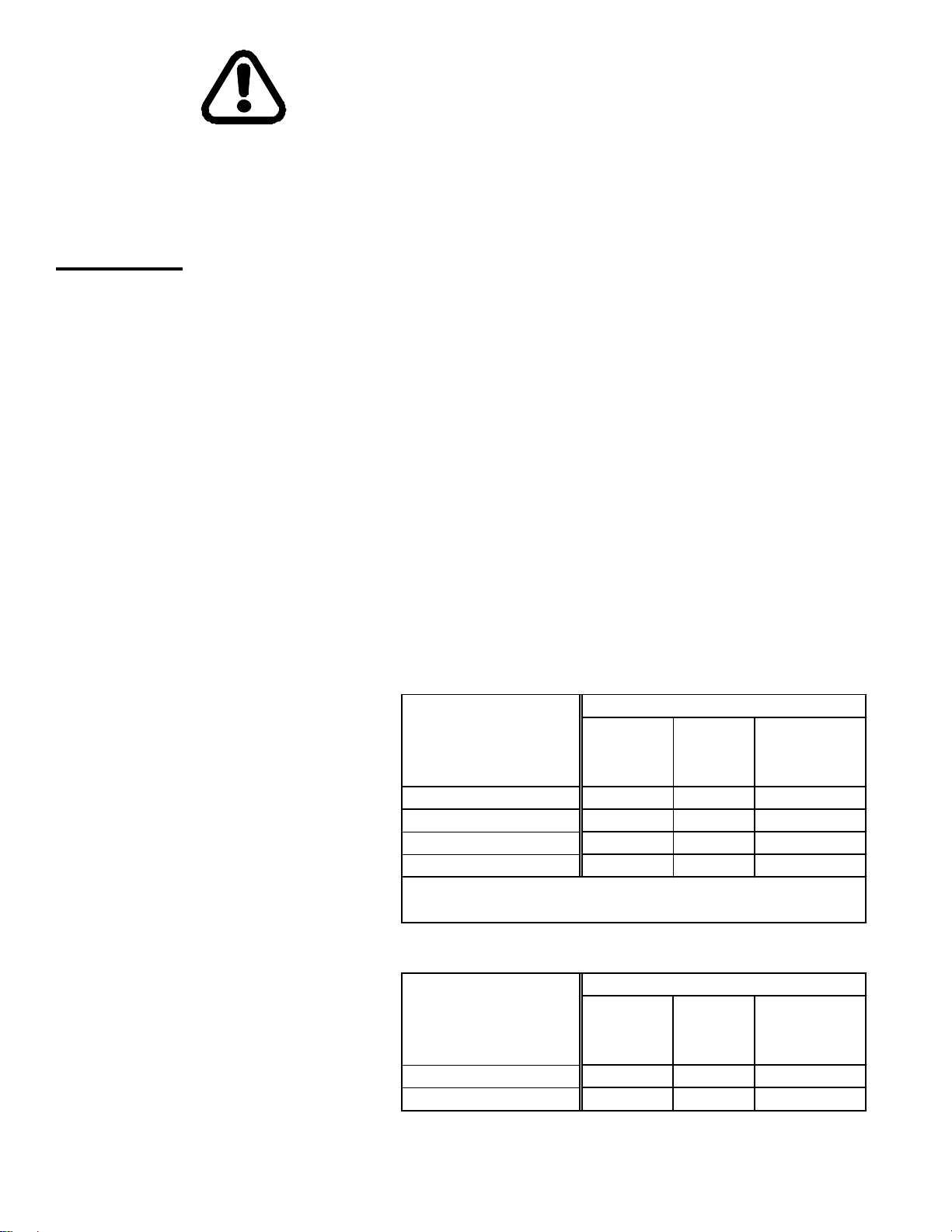
LubricantDescription*
PLANETARY HOIST GEARBOX OIL
PLANETARY HOIST BRAKE OIL
80W140Synthetic ‐25(‐32) 125(52) 225(107)
75W90Synthetic ‐40(‐40) 115(46) 215(102)
80W90Conventional ‐20(‐29) 100(38) 180(82)
85W140Conventional 20(6) 120(50) 200(93)
*UseAPIGL‐5orEPlubricants.
LubricantDescription
SAE20W20 ‐10(‐23) 135(50) 225(107)
MOBI LE1ATF ‐40(‐40) 110(40) 215(102)
Ambient&
Operating
Ambient&
Operating
TempRangeF(C)
Min
Ambient
TempRangeF(C)
Min
Ambient
Max
Max
Max
Operating
Max
Operating
2
Page 4
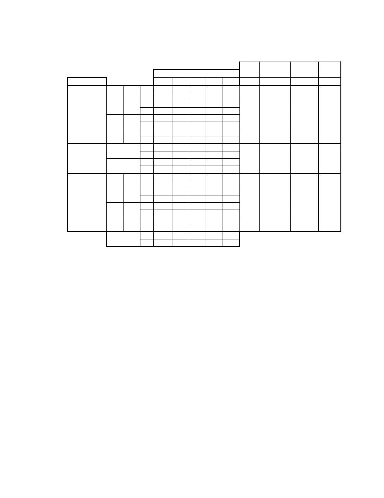
GEARMOTORPERFORMANCE
LAYEROFCABLE
MOTOR1 2 3 4 5 GPM psi lb in
fpm 74 81 88 96 103
LINE
SPEED
mpm 22 25 27 29 31
lb 15000 13500 12200 11200 10300
LINE
PULL
kg 6800 6120 5530 5080 4670
fpm 146 160 175 189 204
LINE
SPEED
mpm 44 49 53 57 62
lb 7500 6700 6100 5600 5100
LINE
PULL
kg 3400 3030 2760 2540 2310
fpm 146 160 175 189 204
mpm 44 49 53 57 62
lb 15000 13500 12200 11200 10300
kg 6800 6120 5530 5080 4670
fpm 80 88 96 104 112
LINE
SPEED
mpm 24 28 29 32 34
lb 15000 13500 12200 11200 10300
LINE
PULL
kg 5440 4890 4440 4080 3760
fpm 155 170 186 201 217
LINE
SPEED
mpm 51 56 61 66 71
lb 6000 5400 4900 4500 4100
LINE
PULL
kg 2720 2440 2220 2040 1850
ft 55 125 195 275 360
m 18 38 60 84 110
2SPEED
1.25/1.25
SINGLESPEED
2.50in
2SPEED
1.50/1.50in
LOW
SPEED
HIGH
SPEED
LINESPEED
LINEPULL
LOW
SPEED
HIGH
SPEED
CABLE
CAPACITY
MAX
FLOW
30 2460 604 5/8
60 2460 578 5/8
40 1970 607 5/8
MAX
PRESSURE
HOIST
WEIGHT
CABLE
SIZE
NOTE: The rated line pulls shown are for the hoist only. Consult the wire rope manufacturer for wire rope ratings.
3
Page 5
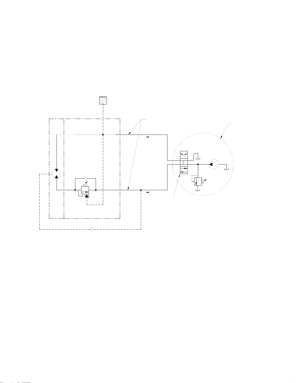
HYDRAULIC SYSTEM REQUIREMENTS
Refer to the performance charts, above, to properly match your hydraulic system to hoist performance.
SINGLE SPEED GEAR MOTOR
BRAKE
MOTOR
COUNTER BALANCE
VALVE
COUNTER BALANCE
PORT #1
MOTOR CASE DRAIN
HIGH PRESSURE LINE
PAYOUT
PAYIN
3 POSITION
4 WAY VALVE
CUSTOMER
SUPPLIED
PUMP
SYSTEM
RELIEF
4
Page 6
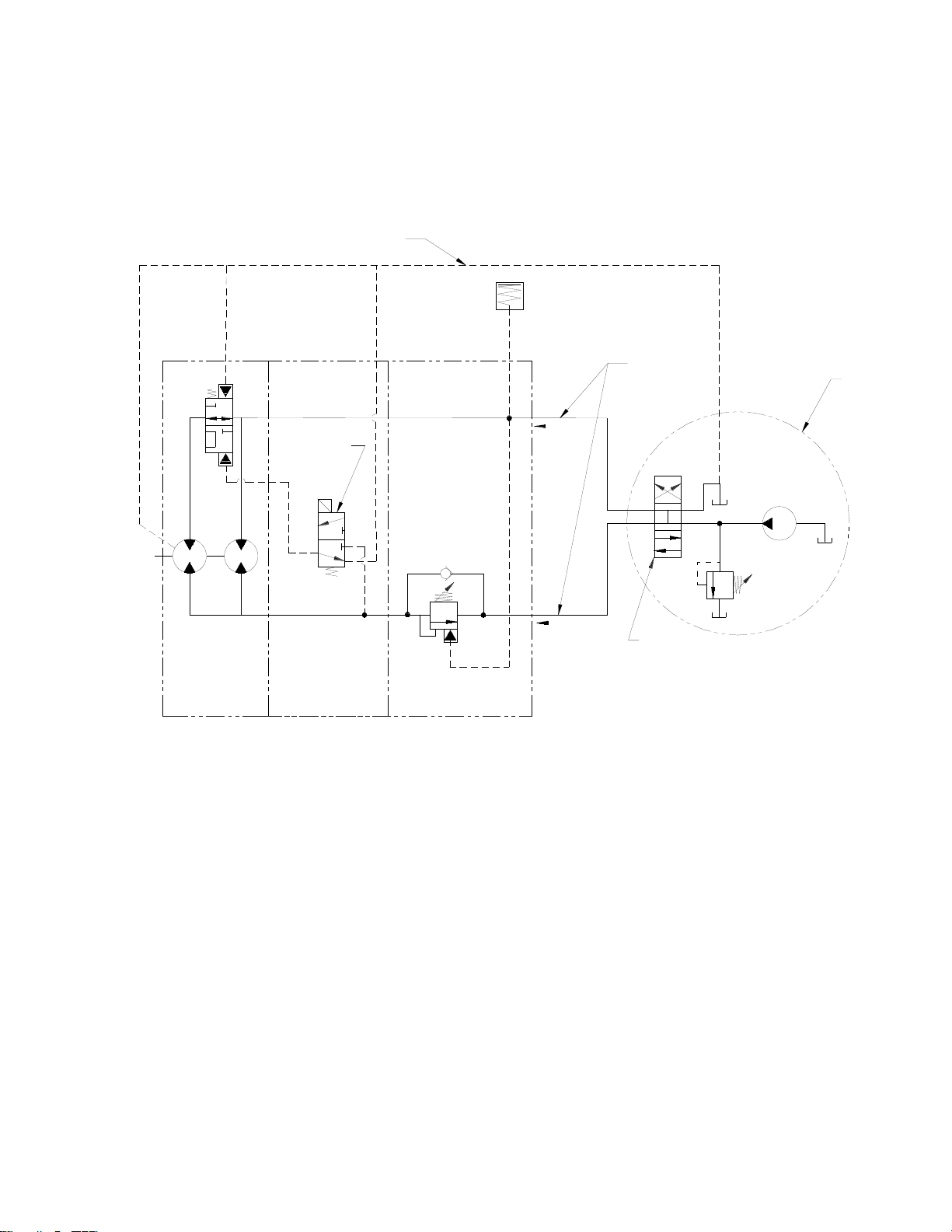
HYDRAULIC SYSTEM REQUIREMENTS cont’
LOW PRESSURE LINE
2 SPEED GEAR MOTOR
DIRECT LINE TO TANK
BRAKE
MOTOR CASE DRAIN
MOTOR 2 SPEED
12 VDC
SHIFT SOLENOID
PORT #5
SPEED SELECTOR
PORT#3
COUNTER BALANCE
VALVE
COUNTER BALANCE
PORT #1
PAYOUT
PAYIN
HIGH PRESSURE LINE
3 POSITION
4 WAY VALVE
CUSTOMER
SUPPLIED
PUMP
SYSTEM
RELIEF
5
Page 7
CABLE INSTALLATION
1. Unwind cable by rolling it out along the ground to prevent kinking. Securely wrap end of wire
rope, opposite hook, with plastic or similar tape to prevent fraying.
2. Slide the wire rope through narrow end of the pocket against the drum flange. Wrap the wire
rope around on the anchor (item #16) and pull the wire rope and anchor back into the wide end
of the pocket. Use a soft hammer to drive the back side of the wire rope, firmly seating the wire
rope and anchor into the pockets
3. Carefully run the hoist in the “reel-in” direction. Keeping tension on end of cable, spool all the
cable onto the cable drum, taking care to form neatly wrapped layers.
16
6
Page 8

HOIST OPERATION
The best way to get acquainted with how your hoist operates is to make test runs before you use it.
Plan your test in advance. Remember, you hear your hoist, as well as see it operate; learn to
recognize the sounds of a light steady pull, a heavy pull, and sounds caused by load jerking or
shifting. Gain confidence in operating your hoist and its use will become second nature with you.
The uneven spooling of cable while pulling a load is not a problem, unless there is a cable pileup
on one end of drum. If this happens reverse the hoist to relieve the load and move your anchor
point further to the center of the vehicle. After the job is done you can unspool and rewind for a
neat lay of the cable.
MAINTENANCE
The owner is to ensure proper inspection intervals, in compliance with ANSI B30.5, 5-2.3, and will review hoist
usage categories on a periodic basis. A Qualified Inspector should perform all maintenance and inspections.
• For hoist in occasional use less than 10 hours per month it is recommended a pre-use inspection and
an annual 12 month inspection based on average use over a quarter.
For hoist in moderate use, more than 10 but less than 50 hours per month, it is recommended a pre-
•
use inspection, quarterly inspection, and an annual 12-month inspection based on average use over a
quarter.
For hoist in heavy use, more than 50 hours per month it is recommended a pre-use inspection, monthly
•
inspection, quarterly inspection, and an annual 12 months inspection.
7
Page 9

TROUBLE SHOOTING GUIDE
CONDITIONS POSSIBLE CAUSE CORRECTION
OIL LEAKS FROM HOIST
HOIST RUNS TOO SLOW
BRAKE WLL NOT HOLD
1. Seals damaged or worn.
2. Too much oil.
3. Damaged o-rings.
4. Case drain not connected.
1. Low flow rate.
2. Hydraulic motor worn out.
1. Incorrect directional control
valve (cylinder spool, closed
center).
2. Excessive hydraulic system
back pressure.
3. Sprag clutch worn out.
1. Replace seal
2. Drain excess oil.
3. Replace o-rings.
4. Connect case drain.
1. Check flow rate. Refer to
Hydraulic Systems
Performance Chart, page 3,4.
2. Replace motor.
1. Use only a motor spool (open
center) directional control
valve.
2. Reduce system back pressure
to less than 100 psi.
3. Replace sprag clutch
mechanism.
BRAKE WILL NOT
RELEASE
HOIST WILL NOT
OPERATE AT HIGH
SPEED
HOIST OPERATES
ERRATICALLY ON
INHAUL
1. Brake line disconnected or
1. Repair brake line.
blocked
1. Shift solenoid not working. 1. Verify shift spool is energized.
1. Sprag hub is reversed. 1. Install sprag hub correctly.
8
Page 10
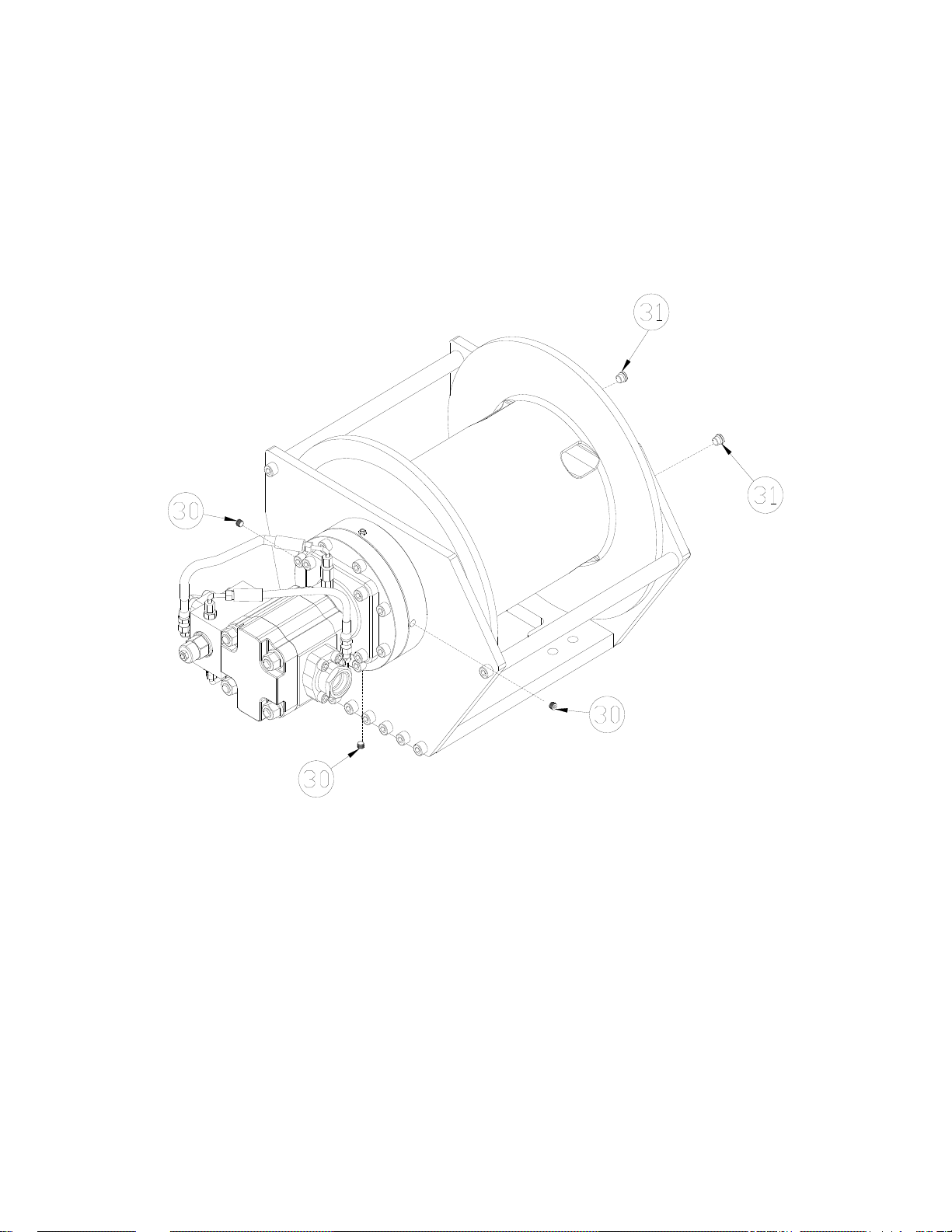
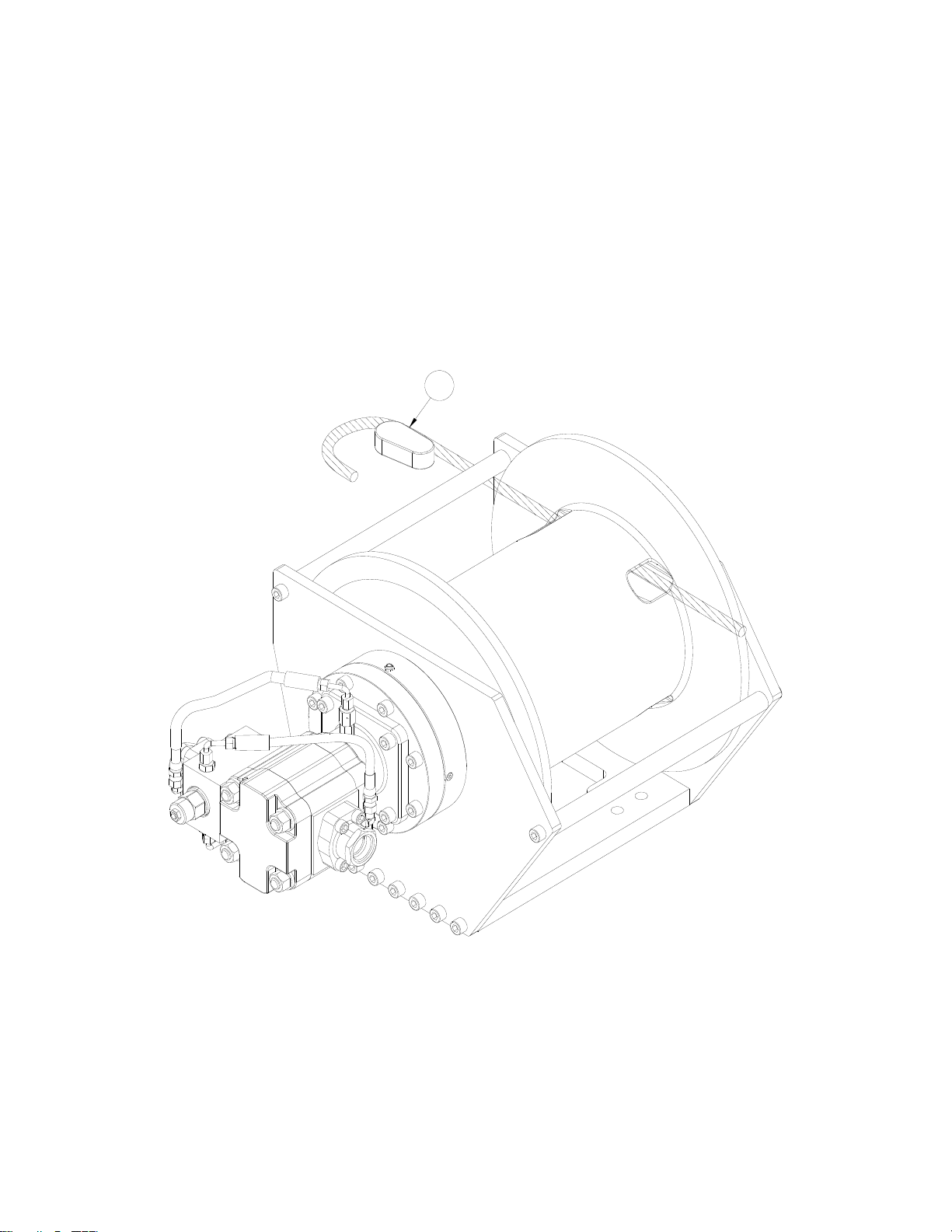
INSTRUCTIONS FOR DISASSEMBLY
1. Remove wire rope from drum.
2. Rotating drum where both plugs #31 are visible thru side plate. Drain oil by removing both
plugs and rotate drum until one plug is at the bottom of the hoist.
3. Remove plugs #30 and drain oil from brake.
4. When replacing lubricant, fill drum at plug #31 with 64oz of applicable lube for your climate
from table on page 2 and fill brake at plug #30 with 16oz of applicable brake lube for your
climate from table on page 2.
9
Page 11

5. Disconnect brake release hose #39 from elbow fitting #22b and coupling #46a. Disconnect
hose #43a from elbow fitting #22a and fitting tube to pipe #53. Remove hose #43b from elbow
fitting #22c and coupling #46b. Remove flange mount #44a by removing (4) bolts #20 from
motor. Remove flange mount #44b by removing (2) bolts #48 and (2) bolts #20.
20
48
22a
43a
53
52
44b
46b
54
46a
22b
39
43b
22c
20
54
44a
10
Page 12

6. Remove (2) fittings #46a and #46b from counterbalance valve #41. Remove counterbalance
valve #41by removing (2) bolts #47. The motor #24 can be removed by removing (4) bolts #50.
47
46b
41
46a
50
24
11
Page 13

7. Remove brake cover #5 by removing (8) bolts #19. The cover is spring loaded, use care
when removing. Remove o-ring #25 then springs #38 may be removed; residual oil may be
present in the brake housing.
8. Remove piston #4 including o-rings and backup rings #26, #27, #28, and #29 by using a
momentary puff of compressed air into the brake port located on top of the end bearing.
Capture the piston by placing a shop rag over the opening prior to using air.
9. Remove the sprag brake hub assembly #3, (8) stator plates #6, and (7) disc brakes #7. The
sprag brake hub assembly #3 is not a serviceable part, if damaged a replacement assembly
should be ordered.
12
Page 14

10. Remove brake housing #11 from side plate #13.
11. Remove the side plate by removing (10) bolts #21.
13
21
11
21
21
13
Page 15

12. Remove base plate #15 and (2) tie bars #32 by removing (10) bolts #21
13. Remove side plate #14 by removing (7) bolts #21 and (1) bolt #40.
14. Seal #35 can now be removed.
15. Uninstall retaining ring #36 and then drum spacer #17 can be removed.
14
Page 16

16. Remove seal #35
17. To remove bearing #12,spacer #42,input carrier assembly #2, and output sun #9, tap output
carrier #1 with a soft hammer on the cable anchor side of drum #8
18. Uninstall retaining ring #37 then bearing#12 can be removed
15
Page 17

DISASSEMBLY OF INPUT CARRIER 41.62 RATIO
Carrier assemblies may be purchased as a complete assembly (see pg. 21) or parts may be
purchased individually (see parts list below). If purchasing individual parts, it will be necessary to
disassemble the input gear carrier as outlined below.
1. Carefully drive roll pin #71 into carrier pin #69 so that it is captured within carrier pin #69 but
not touching the opposite side of the input carrier #66.
2. Tap carrier pin #69 to remove it from the input carrier #66.
3. Slide the planet gear #67 and the (2) thrust washers #70 from the carrier assembly #66.
Bearing #68 may then be pressed out.
4. Remove the roll pin #71 from the carrier pin #69.
ITEM # QTY PART # DESCRIPTION
66 1 317031 MACHINED-CARRIER-INPUT RCH
67 3 334215 GEAR-INPUT-PLANET-RCH
68 3 402138 BEARING-NEEDEL RCH
69 3 470119 PIN-INPUT RCH
70 6 518069 WASHER-THRUST RCH
71 3 470121 SPRING PIN-1/4 X 7/8 LG
70
71
66
70
69
67
68
16
Page 18

ASSEMBLY OF INPUT CARRIER 41.62 RATIO
Note: Item Numbers refer to Carrier parts list on page 16
1. Place carrier #66 on flat clean surface.
2. Place the gear #67 on a flat thin clean metal plate; Align the bearing with the chamfer facing
toward the gear. Using a press, press the bearing flush to the gear surface.
3. Place thrust washer #70 on top of gear #67. Insert carrier pin #69 into carrier #66, aligning roll
pin #71 with the matching hole on the carrier #66.
4. Insert a thrust washer between gear #67 and carrier #66. Completely insert carrier pin #69 into
carrier #66 using care to align the roll pin hole in carrier pin #69 with the roll pin hole in the
carrier #66.
5. Drive roll pin #71 into carrier #66 until roll pin #71 is ¼” past flush with surface of the carrier
#66.
6. Repeat this process to install the two remaining gears into the carrier.
17
Page 19

DISASSEMBLY OF OUTPUT CARRIER
Carrier assemblies may be purchased as a complete assembly (see pg. 21) or parts may be
purchased individually (see below). If purchasing individual parts, it will be necessary to
disassemble the gear carrier as outlined below.
1. Carefully drive roll pin #76 into carrier pin #72 so that it is captured within carrier pin #75 but
not touching the opposite side of the output carrier #72.
2. Tap carrier pin #75 to remove it from the output carrier #72.
3. Slide the gear #73 and thrust washers #74 from the carrier #72
4. Press bearings #77, from the gear #73
5. Remove the roll pin #76 from the carrier pin #75.
6. Repeat this process for the two remaining gears in the carrier.
7. Remove spacer #78 from the carrier #72
76
74
72
74
75
73
77
77
77
78
ITEM # QTY PART # DESCRIPTION
72 1 317014 OUTPUT CA RRIE R
73 3 334210 PLANE T GEAR
74 6 518069 THRU ST WASHER
75 3 470118 CARRI ER PIN
76 3 47012 0 ROLL PIN 3/8 DIA X 7 /8 LG
77 9 402138 BEARI NG-NE EDLE ROLLER
78 1 408386 SPACER
18
Page 20

ASSEMBLY OF OUTPUT CARRIER
Note: Item Numbers refer to Carrier parts list on page 18
1. Place output carrier #72 on flat clean surface.
2. Install spacer #78 into the carrier
3. Press in (3) Bearings #77 into gear #73. Repeat this process to install the bearings in the two
remaining gears.
4. Slide the gear #73 into position in the output carrier #72.
5. Insert a thrust washer #74 between gear #75 and output carrier #72 (both sides of gear).
Completely insert carrier pin #59 into carrier #56 using care to align the roll pin hole in carrier
pin #75 with the roll pin hole in the output carrier #72.
6. Drive roll pin #76 into output carrier #72 until roll pin #76 is flush with surface of the output
carrier #72.
7. Repeat this process to install the two remaining gears into the output carrier.
19
Page 21

RCH 15000 HOSE HOOKUP
41.62 RATIO SINGLE SPEED
43
52
22
53
43
46
22
46
22
20
39
Page 22

RCH 15000 PARTS DRAWING
41.62 RATIO SINGLE SPEED
23
30
22
18
33
3
30
6
30
11
21
21
40
23
35
26
29
38
47
48
20
46
44
22
53
41
46
50
43
49
52
51
53
44
24
53
39
5
19
4
25
43
32
22
20
21
21
34
21
42
13
27
28
1
2
9
12
7
12
37
32
16
36
17
15
31
21
31
8
14
21
21
Page 23

RCH 15000 PARTS LIST
41.62 RATIO SINGLE SPEED
I TEM QT Y PA RT NO DESCRI PT IO N I TEM QT Y PA RT NO DESCRI PT IO N
1 1 296698 ASSY-PLANETA RY OUTPUT 28 1 462084 O-RING 2-362
2 1 296700 ASSY PLANETARY INPUT 29 1 462085 BACKUP RING 8-362
3 1 296702 ASSY-BRAKE HU B SPRAG 30 3 468016 PIPE PLUG-1/8-27NPTF,HEX SOC. HD. Z/P
4 1 306043 BRAKE PISTON 31 2 468043 PLUG,-5 SAE, 1/2"-20 UNF
5 1 328171 BRAKE COVER RCH 32 2 474226 TIE BAR RCH
6 8 330017 STATOR PLATE-BRAKE 33 1 486089 SEAL-SHA FT OIL
7 7 330018 FRICTION PLA TE-BRAKE 34 1 486090 SEAL-SHAFT OIL
8 1 332258 CABLE DRUM 35 1 486091 SEAL-SHA FT OIL
9 1 334211 GEAR-OUTPUT-SUN 36 1 490059 RI NG-RETAININ G-DIN 471-130
10 NOT USED 37 1 490060 RI NG RETAI NI NG DIN 472-200
11 1 338384 BRAKE-HOUSI NG 38 12 494129 SPRING-BRAKE- 385LB I N/IN
12 2 402137 BALL BEARING -DRUM 39 1 509136 HOSE ASSY-HY D BRAKE RELEASE
13 1 408389 SIDE PLATE-INPU T 40 1 514019 SPECIAL CAPSCREW-1/2-13 UNC X 1.50 LG HX HD GR8 Z/P
14 1 408390 SIDE PLATE-OUTPUT 41 1 516046 VALVE-MOTOR CONTROL
15 1 408385 PLATE-BASE 42 1 518068 SPACER-BEARING-DRUM
16 1 408387 WEDGE CABLE 43 2 509137 HOSE ASSEM BLY
17 1 412126 SPACER-DRUM 44 2 432061 SAE 1.313-12 FLANG E MOUNT WITH -4 PORT
18 1 412128 BUSHING-BRAKE 46 2 432051 COUPLING STRAIGH T THREAD 37DEG FLARE SAE ORB
19 8 414595 CAPSCREW-1/2-13 X 3.5 LG SOC HD 47 2 414432 CAPSCREW -7/16-14 X 3.50 LG. SOC HD.
20 2 414431 CAPSCREW -7/16-14 X 1.75 LG. SOC HD. 48 2 414434 CAPSCREW-7/16-14 X 4.25 LG SOC HD
21 27 414952 CAPSCREW-1/2-13NCX1 1/2LG,SOCHD,Z/P 49 1 462081 O-RING 2-159
22 2 432018 FITTING Parker#4-C5OX-S T-LOK, 7/16-20 90 degree 50 4 414512 CAPSCREW-1/2-13 X 1.5 LG H X HD GR8 Z /P
23 2 456008 RELIEF FIT-1/8-27PFT,BALL CHECK,Z/P 51 1 432056 CHECK VALVE-INLIN E
24 1 458158 M OTOR- 2.25 GEAR SECTION 52 1 432055 FITTING-I NDUSTRIAL TUBE TO PIPE
25 1 462063 O-RING-AS-568-165 53 3 462099 O-RING 2-222
26 1 462082 O-RING 2-358
27 1 462083 BACKUP RING 8-357
22
Page 24

RCH 15000 PARTS DRAWING
41.62 RATIO 2 SPEED
23
30
22
18
33
3
30
6
30
11
21
21
40
23
35
26
43
20
47
48
51
51
59
45
39
57
46
41
59
44
22
49
51
24
54
53
52
55
50
22
5
19
58
21
21
38
29
27
28
4
25
35
21
32
1
2
42
9
12
13
7
12
32
16
36
17
37
15
31
21
31
8
14
21
23
Page 25

RCH 15000 PARTS LIST
41.62 RATIO 2 SPEED
IT EM Q TY PART NO DESCRI PTIO N IT EM Q T Y PART NO DESCRI PT I ON
1 1 296698 ASSY-PLANETARY OUTPUT 30 3 468016 PIPE PLUG-1/8-27NPTF,HEX SOC. HD. Z/P
2 1 296700 ASSY PLANETA RY INPU T 31 2 468043 PLUG,-5 SAE, 1/2"-20 UNF
3 1 296702 ASSY-BRAKE HUB SPRAG 32 2 474226 TI E BAR RCH
4 1 306043 BRAKE PISTON 33 1 486089 SEAL-SHAFT OIL
5 1 328171 BRAKE COVER RCH 34 1 486090 SEAL-SHAFT OIL
6 8 330017 STATOR PLATE-BRAKE 35 1 486091 SEAL-SHAFT OIL
7 7 330018 FRICTION PLA TE-BRAKE 36 1 490059 RING-RETAINING-DIN 471-130
8 1 332257 CABLE DRUM 37 1 490060 RING RETAINING DIN 472-200
9 1 334211 G EAR-OUTPUT-SUN 38 12 494129 SPRING -BRAKE- 385LB IN/IN
10 NOT USED 39 1 509138 H OSE ASSY-HYD BRAKE RELEASE
11 1 338384 BRAKE-HOUSING 40 1 514019 SPECIAL CAPSCREW-1/2-13 UNC X 1.50 LG HX HD GR8 Z/P
12 2 402137 BALL BEARI NG-DRUM 41 1 516046 V ALV E-MOTOR CONTROL
13 1 408383 SIDE PLATE-INPU T 42 1 518068 SPACER-BEARING-DRUM
14 1 408384 SIDE PLATE-OUTPUT 43 1 509140 H OSE ASSEMBLY
15 1 408385 PLATE-BASE 44 4 414512 CAPSCREW-1/2-13 X 1.5 LG HX HD GR8 Z/P
16 1 408387 WEDGE CABLE 45 1 432060 SAE 1.313-12 FLANG E MOUNT
17 1 412126 SPACER-DRUM 46 1 432051 COUPLING STRAIGHT THREAD 37DEG FLARE SAE ORB
18 1 412128 BUSHING-BRAKE 47 2 414435 CAPSCREW -7/16-14 X 5.00 LG SOC HD
19 8 414438 CAPSCREW-1/2-13X 3.5 LG SOC HD 48 2 414436 CAPSCREW 7/16-14-5.75 LG SOC HD.
20 2 414431 CAPSCREW -7/16-14 X 1.75 LG. SOC HD. 49 1 516057 2 SPD SHI FT BLOCK
21 27 414952 CAPSCREW-1/2-13NCX1 1/2LG,SOCHD,Z/P 50 1 509139 H OSE ASSEMBLY
22 2 432018 FI TTING Parker#4-C5OX-S T-LOK, 7/16-20 90 degree 51 2 509141 H OSE ASSEMBLY
23 2 456008 RELIEF FIT-1/8-27PFT,BALL CHECK,Z/P 52 2 432023 FI TTING -7/16-20,PARKER#0503-4-4/EQ
24 1 458154 MOTOR-1.00 & 1.25 GEAR SECTIONS 53 1 432046 SWIVEL CONNECTOR 37 DEG SWIVEL / NPTF
458156 MOTOR-1.00 & 1.00 GEAR SECTIONS 54 1 432047 U NI ON ELBOW 37 DEG FLARE / 37 DEG. FLARE
25 1 462063 O-RING-AS-568-165 55 1 432048 TEE SWI VEL NU T RUN 37 DEG FLARE
26 1 462082 O-RING 2-358 56 1 432049 TEE STRAIGH T THREAD BRANCH 37DEG FLARE SAE ORB
27 1 462083 BACKUP RING 8-357 57 1 432052 MA LE 90 DEG. ELBOW -37 DEG FLARE / SAE-ORB
28 1 462084 O-RING 2-362 58 1 462081 O-RING 2-159
29 1 462085 BACKUP RING 8-362 59 3 462099 O-RING 2-222
24
Page 26

RCH 15000 20 INCH FLANGE PARTS DRAWING
41.62 RATIO 2 SPEED
23
30
22
18
33
3
30
6
30
11
21
21
40
23
35
26
43
20
47
48
51
51
59
45
39
57
46
41
59
44
22
49
51
24
54
53
52
55
50
22
5
19
58
21
21
38
29
27
28
4
25
35
21
32
1
2
42
9
12
13
7
12
32
16
36
17
37
15
31
21
31
8
14
21
25
Page 27

RCH 15000 20 INCH FLANGE PARTS LIST
41.62 RATIO 2 SPEED
IT EM Q TY PART NO DESCRI PTIO N IT EM Q T Y PART NO DESCRI PT I ON
1 1 296698 ASSY-PLANETARY OUTPUT 31 2 468043 PLUG ,-5 SAE, 1/2"-20 UNF
2 1 296700 ASSY PLANETA RY IN PU T 32 2 474226 TI E BAR RCH
3 1 296702 ASSY-BRAKE HUB SPRAG 33 1 486089 SEAL-SHAFT OIL
4 1 306043 BRAKE PISTON 34 1 486090 SEAL-SHAFT OIL
5 1 328171 BRAKE COVER RCH 35 1 486091 SEAL-SHAFT OIL
6 8 330017 STATOR PLATE-BRAKE 36 1 490059 RING-RETAINING -DIN 471-130
7 7 330018 FRICTION PLA TE-BRAKE 37 1 490060 RING RETAINING DIN 472-200
8 1 332259 CABLE DRUM 38 12 494129 SPRING -BRAKE- 385LB IN/IN
9 1 334211 G EAR-OUTPUT-SUN 39 1 509138 H OSE ASSY-HYD BRAKE RELEASE
10 NOT USED 40 1 514019 SPECIAL CAPSCREW-1/2-13 UNC X 1.50 LG HX HD GR8 Z/P
11 1 338384 BRAKE-HOUSING 41 1 516046 V ALV E-MOTOR CONTROL
12 2 402137 BALL BEARI NG-DRUM 42 1 518068 SPACER-BEARING-DRUM
13 1 408391 SIDE PLATE-INPU T 43 1 509140 H OSE ASSEMBLY
14 1 408392 SIDE PLATE-OUTPUT 44 4 414512 CAPSCREW-1/2-13 X 1.5 LG HX HD GR8 Z/P
15 1 408385 PLATE-BASE 45 1 432060 SAE 1.313-12 FLANG E MOUNT
16 1 408387 WEDGE CABLE 46 1 432051 COUPLING STRAIGHT THREAD 37DEG FLARE SAE ORB
17 1 412126 SPACER-DRUM 47 2 414435 CAPSCREW -7/16-14 X 5.00 LG SOC HD
18 1 412128 BUSHING-BRAKE 48 2 414436 CAPSCREW 7/16-14-5.75 LG SOC HD.
19 8 414438 CAPSCREW-1/2-13X 3.5 LG SOC HD 49 1 516057 2 SPD SHI FT BLOCK
20 2 414431 CAPSCREW -7/16-14 X 1.75 LG. SOC HD. 50 1 509139 H OSE ASSEMBLY
21 27 414952 CAPSCREW-1/2-13NCX1 1/2LG,SOCHD,Z/P 51 2 509141 H OSE ASSEMBLY
22 2 432018 FI TTING Parker#4-C5OX-S T-LOK, 7/16-20 90 degree 52 2 432023 FITTING-7/16-20,PARKER#0503-4-4/EQ
23 2 456008 RELIEF FIT-1/8-27PFT,BALL CHECK,Z/P 53 1 432046 SWIVEL CONNECTOR 37 DEG SWIVEL / NPTF
24 1 458158 MOTOR-1.25 & 1.25 GEAR SECTIONS 54 1 432047 U NION ELBOW 37 DEG FLARE / 37 DEG. FLARE
25 1 462063 O-RING-AS-568-165 55 1 432048 TEE SWI VEL NU T RUN 37 DEG FLARE
26 1 462082 O-RING 2-358 56 1 432049 TEE STRAIGH T THREAD BRANCH 37DEG FLARE SAE ORB
27 1 462083 BACKUP RING 8-357 57 1 432052 MA LE 90 DEG. ELBOW -37 DEG FLARE / SAE-ORB
28 1 462084 O-RING 2-362 58 1 462081 O-RING 2-159
29 1 462085 BACKUP RING 8-362 59 3 462099 O-RING 2-222
30 3 468016 PIPE PLUG-1/8-27NPTF,HEX SOC. HD. Z/P
26
Page 28

15K 41.62 RATIO 2.5 IN SINGLE SPEED DIMENSIONAL DRAWING
27
Page 29

15K 41.62 RATIO 1.25&1.25 AND 1.50&1.50 IN 2 SPEED DIMENSIONAL DRAWING
WINCH MODEL
1.25 & 1.25 INCH TWO SPD
1.50 & 1.50 INCH TWO SPD
A
INCHES
32.67
33.17
28
Page 30

15K 41.62 RATIO 20 INCH FLANGE 1.25&1.25 IN 2 SPEED DIMENSIONAL DRAWING
29
Page 31

NOTES:
30
Page 32

LIMITED WARRANTY
RAMSEY WINCH warrants each new RAMSEY WINCH to be free from defects in
material and workmanship for a period of one (1) year from date of purchase.
The obligation under this warranty, statutory or otherwise, is limited to the
replacement or repair at the Manufacturer's factory, or at a point designated by the
Manufacturer, of such part that shall appear to the Manufacturer, upon inspection of
such part, to have been defective in material or workmanship.
This warranty does not obligate RAMSEY WINCH to bear the cost of labor or
transportation charges in connection with the replacement or repair of defective
parts, nor shall it apply to a product upon which repair or alterations have been
made, unless authorized by Manufacturer, or for equipment misused, neglected or
which has not been installed correctly.
RAMSEY WINCH shall in no event be liable for special or consequential damages.
RAMSEY WINCH makes no warranty in respect to accessories such as being
subject to the warranties of their respective manufacturers.
RAMSEY WINCH, whose policy is one of continuous improvement, reserves the
right to improve its products through changes in design or materials as it may deem
desirable without being obligated to incorporate such changes in products of prior
manufacture.
If field service at the request of the Buyer is rendered and the fault is found not to
be with RAMSEY WINCH's product, the Buyer shall pay the time and expense to
the field representative. Bills for service, labor or other expenses that have been
incurred by the Buyer without approval or authorization by RAMSEY WINCH will not
be accepted.
See warranty card for details.
RAMSEY WINCH COMPANY
Post Office Box 581510
Tulsa, Oklahoma 74158-1510
Telephone: (#918) 438-2760 FAX: (#918) 438-6688
OM-914230-0509-A
31
 Loading...