

Ramsey QRP30 User Manual

30 METER (10MHz)
CW TRANSMITTER
Ramsey Electronics Model No. QRP30
THE RAMSEY QRP30 IS AN AMAZING PERFORMER
THAT WILL WORK THE WORLD ON ABOUT A WATT!
FOLKS OF ALL AGES HAVE SUCCESSFULLY BUILT
AND ENJOYED THIS EASY, FUN KIT.
• Ideal for portable or travel fun
• VCXO design allows up to 5 - 8 KHz of tuning about the crystal
frequency
• Front panel switching of TWO channels and includes a crystal for
10.108 MHz, the International QRP frequency
• Excellent and clean keying waveform
• Built-in antenna T-R switch
• Operates on 12 - 15 volts DC at 1/4 amp current
• Appoximately 1 Watt RF power
• Clear, concise step-by-step instructions carefully guide you to a
finished kit that not only works - but you’ll also learn too!
• Proven design that has won many of awards for operators around
the country!
• Add our case and knob set for a finished ‘Pro’ look. Cases match all
Ramsey products
QRP30 • 1

RAMSEY TRANSMITTER KITS
• FM100B Professional FM Stereo Transmitter
• FM25B Synthesized Stereo Transmitter
• AM1, AM25 AM Transmitters
• TV6 Television Transmitter
RAMSEY RECEIVER KITS
• FR1 FM Broadcast Receiver
• AR1 Aircraft Band Receiver
• SR2 Shortwave Receiver
• AA7 Active Antenna
• SC1 Shortwave Converter
RAMSEY HOBBY KITS
• SG7 Personal Speed Radar
• SS70A Speech Scrambler
• SP1 Speakerphone
• WCT20 Wizard Cable Tracer
• PH10 Peak hold Meter
• LC1 Inductance-Capacitance Meter
RAMSEY AMATEUR RADIO KITS
• DDF1 Doppler Direction Finder
• HR Series HF All Mode Receivers
• QRP Series HF CW Transmitters
• CW7 CW Keyer
• CPO3 Code Practice Oscillator
• QRP Power Amplifiers
RAMSEY MINI-KITS
Many other kits are available for hobby, school, Scouts and just plain FUN. New
kits are always under development. Write or call for our free Ramsey catalog.
30 METER CW TRANSMITTER KIT INSTRUCTION MANUAL
Ramsey Electronics publication No. QRP30 Revision 1.3
First printing: January 1995
COPYRIGHT 1994 by Ramsey Electronics, Inc. 590 Fishers Station Drive, Victor, New York
14564. All rights reserved. No portion of this publication may be copied or duplicated without the
written permission of Ramsey Electronics, Inc. Printed in the United States of America.
QRP30 • 2
Ramsey Publication No. QRP30
Price $5.00
KIT ASSEMBLY
AND INSTRUCTION MANUAL FOR
QRP30 30 METER CW
TRANSMITTER KIT
TABLE OF CONTENTS
Introduction to the QRP30 ............. 4
Understanding power levels ........... 5
Circuit description .......................... 8
Simplified Block diagram ................ 8
Parts list ......................................... 9
Schematic Diagram ...................... 10
Parts layout diagram .................... 11
Assembly instructions .................. 12
Crystal oscillator testing ............... 16
Initial tests .................................... 17
Verifying RF power ...................... 18
Maximizing RF power output ....... 19
Options for finishing project ......... 20
Enclosure ideas ........................... 20
Choosing crystals ......................... 21
Troubleshooting guide ................. 22
Ramsey kit warranty .................... 23
QRP30 • 3
RAMSEY ELECTRONICS, INC.
590 Fishers Station Drive
Victor, New York 14564
Phone (585) 924-4560
Fax (585) 924-4555
www.ramseykits.com

INTRODUCTION:
Most "QRP" transmitters are one-of-a-kind experimental circuits which take
some patience and fine-tuning to get clean keying and satisfactory
performance. Most QRP building projects presume either unlimited radio
junkboxes with all the right coils and capacitors, or that you have a lot of time
on your hands to track down needed parts. And that is part of what ham radio
can be all about. The purpose of the Ramsey Electronics series of QRP
transmitters is to give our amateur radio customers the option of picking up a
truly complete and reliable transmitter kit for whenever you need a compact
CW rig for a particular opportunity, perhaps a camping or business trip or a
weekend contest, or something economical to share with a favorite new
Novice.
This transmitter is a serious and practical device for radio amateurs with
general interests, as well as for QRP enthusiasts.
NOTE TO NEWCOMERS: "QRP" is amateur radio shorthand referring to
operation at "reduced power". As a standard "QRP30-signal", the CW
expression "QRP?" really means all of this: "If you are receiving me so well,
and since the FCC requires that we use minimum power necessary to
maintain useful communication, do you think I should reduce transmitting
power?" The act of reducing power output can be the switching off of a linear
power amplifier, or switching from 25 to 5 watts on your new Radio Shack 10
meter rig or turning back the carrier level control on most modern
transceivers. For equipment description and contest competition purposes,
"QRP" refers to transmitter powers under 5 watts.
In our manuals for the Ramsey Amateur Band receivers for the 80 and 40
meter bands, which tend to be of interest to many beginners because of
available Novice and Technician operating privileges, we try to be very basic
and patient, hoping that such an approach will be helpful to radio newcomers as well as to casual, licensed amateurs who just did not know that worthwhile
radio gear could be constructed at Ramsey's low prices, even in the 1990's.
Talking through a transmitter project presents a different challenge. Talking
through a multi-stage transmitter that delivers a grand total of one or two watts
to your antenna is an even greater challenge. In these times when a "barefoot
rig" is assumed to be an imported, digitally-synthesized transceiver putting out
over 100 watts at a cost of $1000-2000.00, we need a sensible and helpful
way of talking about this QRP transmitter you are about to construct.
It's easy to prove that Ramsey's popular and economical receivers work just
fine. Build one right, turn it on, and we become easily convinced. A
transmitter is a different story, especially a transmitter that runs low QRP
QRP30 • 4

power! Different from a receiver, you want to see some measurable output
power and you especially want to make two-way contacts!
If you're studying this manual before deciding to try this Ramsey "QRP"
transmitter project, perhaps the following discussion will be helpful to you. The
purpose of this manual is to help you construct this Ramsey Electronics 4stage, variable-frequency CW transmitter efficiently and successfully, not
necessarily to "sell" you on the merits and fun that have been discovered in
ham QRP operation. The purpose of the following discussion of power levels
and signal reports is simply to assure you that your new Ramsey QRP
transmitter is capable of serious, long-distance communication.
1000 WATTS vs 1 WATT: UNDERSTANDING THE DIFFERENCE
Before we move on, I would like to share with you a practical formula about
transmitter power that I clung to in my younger years when I could not afford
anything other than my original Novice CW transmitter, even well after I got
my Extra Class license. First, some theoretical facts we should know:
• 1. An "S-unit" on a receiver's S-meter or in the R-S-T system consists of a
6 - decibel increase or decrease of output power received from a
transmitter.
• 2. Power needs to be increased four times or 400% to result in a true 1 S-
unit or 6db RST gain.
• 3. Reducing output power down to 25% of previous power should result in
an S- Meter or RST drop of only one 6-db unit.
• 4. A 10 - decibel increase in signal strength requires a power increase of
ten times!
Next, there are three practical facts to remember:
• 1. The R-S-T system was designed originally for the human ear and was
based on typical receiver performance of over 50 years ago.
• 2. Modern receiver design permits signals which are technically "weak" in
measured decibels to sound quite good (ie: 569-579) to the ear.
• 3. The human ear is sensitive enough to appreciate a 1 or 2 db change in
signal strength, which is why moderate changes in output power often
result in more dramatic signal report changes. (In fact, the value of a
decibel was determined to be that increment of sound change which
the ear could detect!)
The following example shows RST reports to be expected, in exact theory, at
various power reduction levels. We will start with the classic 1000 watt station
QRP30 • 5

which gets a report of "10 db. over S-9" measured on the receiving station's Smeter. Assume identical dipole antennas at both stations. Our chart does not
start at the proverbial "30 db. over S-9" and work itself down to S-1 for
reasons that will become obvious.
S9+10 db. 1000 watts output
S9 100 watts output
S8 25 watts output
S7 6.25 watts output
S6 1.56 watts output
S5 .39 watts output
We can see that it becomes easy to play games with such numbers. For
example, an RST of 439 is a legitimate report which permits reasonably
effective communication. But, do we believe that the transmitting station
illustrated above could really produce a 439 signal by running .0013 watt? If
we say "probably not", we also ask why not, and then we would get the
seminars about perfect antenna matching, transmission line losses, and so
forth.
Under good propagation conditions, SSB signal reports of "20 over S-9" and
more can be given without even needing 1000 watts or a beam antenna.
Assuming the "+20" is an accurate report, consider this example of power
reduction over the same path:
S9+20db. 1000 watts
S9+10db. 100 watts
S9 10 watts
S8 2.5 watts
S7 .625 watts
S6 .156 watt
S5 .039 watt
S4 .0087 watt!
Under reasonably good band conditions, particularly at 10 or 14 MHz and on
up, the above correlation of signal reports to power output becomes realistic.
"S9+20" is what amplifier users expect to give and receive to justify their
investment and power consumption. Most commercial transceivers have
typical output in the 60-200 watt range, and S8-9 reports are taken for
granted. Actually, 15-25 watts is a far more practical operating power than
most amateurs and equipment vendors realize today...and the thousands of
QRP enthusiasts will confirm that getting a solid 579 running 3-4 watts is no
big deal.
If all the above theoretical signal reports are based on both the transmitting
and receiving stations using simple dipole antennas, we can also see that the
QRP30 • 6

use of some 10db gain antenna such as a beam or quad by either station
could move the S7 for .625 watt up to S8, and that a similar antenna used at
the other station could give the under 1 watt signal a further boost over S9!
On the other hand, if you hear a 1000 watt station producing a moderate
signal such as S4 or S5, you can reasonably assume that you will not have a
lot of luck over that path right now with the theoretical S1 signal level of your
QRP transmitter.
While these figures also can be used to show how nice it is to have a power
amplifier and beam antenna, they indeed serve to show that reasonable signal
levels indeed are achievable with low power and a dipole antenna.
"QRP" enthusiasts have their own rituals, jargon, strategies, QRP operating
contests, magazine columns and books, and convention get-togethers. They
constitute a vital segment of the amateur radio community, because they
consistently demonstrate the feasibility of low-power communication. In fact,
the most avid QRP enthusiasts would not regard communication with a
Ramsey transmitter especially challenging, since they prefer the new world of
milliwatt operation, known as "QRPp"! And, yes, the ones who have
conquered the "milliwatt" world ARE setting records with "milliwatt" tests. With
the world record set in 1970 between Alaska and Oregon on ONE microwatt,
think about it this way: your Ramsey QRP transmitter is almost one million
times more powerful than the transmitter used in that historic test!
WHO SHOULD USE A "QRP" TRANSMITTER?
There is a philosophy that "Novices" should not get started with a very low
power transmitter. The reasoning is that most newly-licensed amateurs need
to build up the confidence that comes with actually making contacts and that
they do not need the additional challenge and pressure of low-power
operation. There is some wisdom in this view, but that opinion should not
make newcomers apprehensive about trying a Ramsey QRP transmitter, IF:
1. This is where your budget is.
2. You can count on somebody to help you with assembly.
3. You can count on somebody to listen to your signal during initial
tests.
4. You have a reasonably good receiver.
5. You have space for a normal, no-compromise antenna for the band
you wish to operate, either a standard dipole, or the "inverted V"
dipole, or quarter-wave vertical.
QRP30 • 7
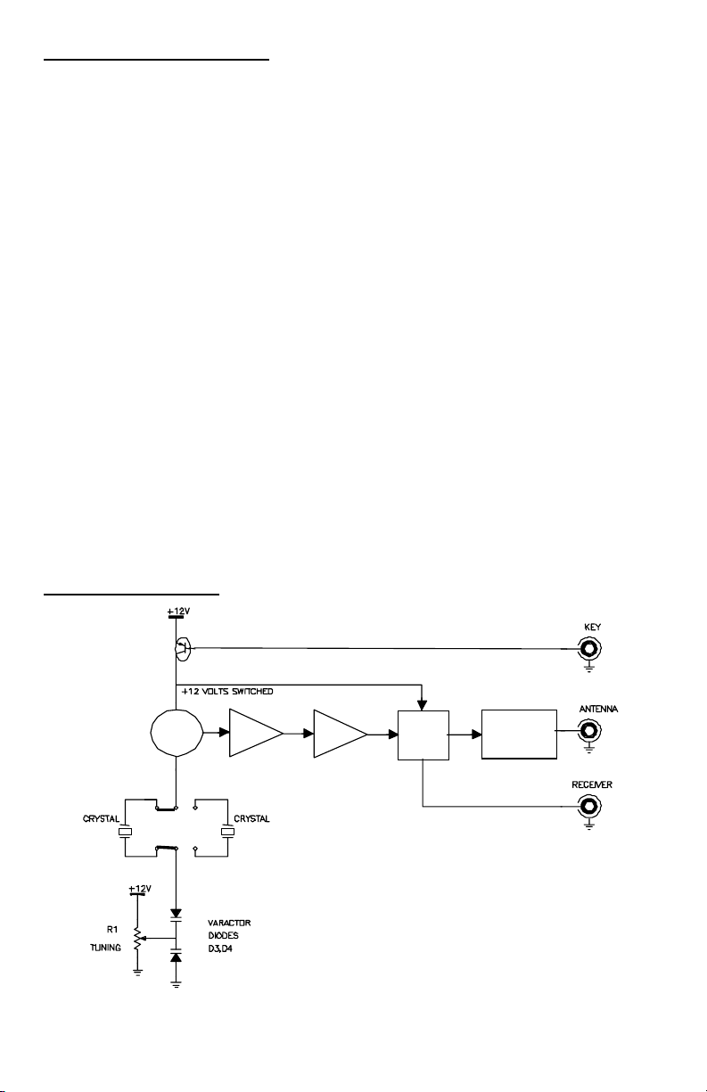
CIRCUIT DESCRIPTION:
In brief, Q1 is a crystal oscillator, amplified by buffer stage Q2, which drives
Q3 as the RF output amplifier. Q4 is a PNP keying circuit which opens and
closes the 12VDC supply line to Q1 and the T-R circuitry of D1 and D2.
S1 selects either of two crystals. R1,D3,D4 and L1 form a varactor controlled
series resonant circuit with the crystal. Adjusting R1 permits a crystal
frequency swing of up to 5 KHz, about the crystal frequency.
Q3 is a Class C RF amplifier that amplifies the RF output of Q2 to the final RF
power output level.
L6,C17 and C18 form a low pass filter (Butterworth) to match the output of Q3
to the antenna and reduce harmonics to acceptable levels as specified by the
FCC.
When the keying line is closed, Q4 conducts +12VDC to the oscillator stage,
applies a positive bias to the base of Q2 through R8, and +12VDC through
choke L4 to the anode of D1, which permits RF to pass through D1 to the filter
network while applying negative bias to D2 which blocks RF from passing to
the receiver. When the keying line is open, the +12VDC applied to D2 through
R13 permits D2 to conduct from the antenna jack to the receiver jack. The
buffer and amplifier stages are not keyed, resulting in clean keying, free of
chirps and clicks.
BLOCK DIAGRAM:
Q1
OSC.
A B
Q2
BUFFER
Q3
FINAL
AMP
QRP30 • 8
D1, D2
DIODE
SWITC H
C17.L5,C18
LOW PASS
FILTER
 Loading...