


280-F
Frozen Fry Dispenser
Equipment Manual
English (Rev H)
P/N 293511
Manufactured By
Automated Equipment LLC
5140 Moundview Drive
Red Wing, MN 55066 U.S.A.
For Warranty Service & Technical Support:
US & Canada call: |
1 (800) 248-2724 |
|
International call: |
1 (651) 385-2273 |
|
Sales Fax: |
1 (651) 385-2166 |
|
Service Fax: |
1 (651) 385-2172 |
|
http://www.autoequipllc.com |
|
|
Business Hours: |
|
|
Monday – Friday: 8:00 AM to 5:00 PM CST |
|
|
(excluding. holidays) |
|
|
After hours, your call will be handled by a voice mail |
|
|
paging service. The on-call technician will be paged and |
|
|
will return your call. |
|
|
Introduction |
Table of Contents |
1 |
|
||
Unpacking & Installation ........................................................................................................................ |
|
1 |
Intended Use ........................................................................................................................................... |
|
1 |
Specifications.......................................................................................................................................... |
|
1 |
Warranty .................................................................................................................................................. |
|
2 |
Service Information ................................................................................................................................ |
|
3 |
Equipment Safety.................................................................................................................................... |
|
4 |
Dispenser Assembly (Models prior to s/n 28FR0802B0249)............................................................... |
6 |
|
Dispenser Assembly (Models after and including s/n 28FR0802B0249) ........................................... |
9 |
|
Disassembly, Defrost & Cleaning........................................................................................................ |
12 |
|
Dispenser Startup ................................................................................................................................. |
|
13 |
Operation ............................................................................................................................................... |
|
14 |
Daily Opening and Closing .................................................................................................................. |
|
15 |
User Function Menu Structure ............................................................................................................ |
18 |
|
Manager Function Menu Structure...................................................................................................... |
19 |
|
Diagnostic Function Menu Structure .................................................................................................. |
20 |
|
Error Detection...................................................................................................................................... |
|
23 |
Troubleshooting.................................................................................................................................... |
|
24 |
Calibrations and Adjustments ............................................................................................................. |
27 |
|
Part Identification.................................................................................................................................. |
|
30 |
Refrigeration System............................................................................................................................ |
|
40 |
Electrical Diagram – Two Temperature Probe Configuration........................................................... |
44 |
|
Electrical Diagram – Single Temperature Probe Configuration ....................................................... |
45 |
|
Copyright © 2011 Automated Equipment LLC All rights reserved.
The information in this manual is subject to change without notice.
IN NO EVENT WILL AUTOMATED EQUIPMENT LLC BE LIABLE FOR TECHNICAL OR EDITORIAL OMISSIONS MADE HEREIN, NOR FOR DIRECT, SPECIAL, INCIDENTAL, OR CONSEQUENTIAL DAMAGES RESULTING FROM THE FURNISHING, PERFORMANCE,
OR USE OF THIS MATERIAL.
This manual is copyrighted with all rights reserved. Under the copyright laws, this manual may not be copied, in whole or part, without the written consent of Automated Equipment LLC.
Product names mentioned herein are for identification purposes only, and may be trademarks and/or registered trademarks of their respective companies.
Copyright © 2011 Automated Equipment LLC All rights reserved.

RAM™ 280-F Frozen Fry Dispenser
Introduction
This manual contains important information on the proper installation, operation, and care of the RAM 280-F Frozen Fry Dispenser. Following the instructions and procedures in this document will ensure that your dispenser provides years of reliable service. If any problems with the dispenser arise, this manual will also provide troubleshooting tips and service information.
Unpacking & Installation
Remove all packing material from Dispenser. Open Cabinet Door. Disassemble, clean, sanitize and dry the Hopper and Accumulator assemblies. Clean, sanitize and dry Fry Baskets. (see pages 6-12 for assembly, disassembly & cleaning). Reassemble all components (see pages 13-17 for startup and operation).
Specifications
Electrical Requirements:
Domestic:
•120 Volts a.c., 60 Hertz, 8 Amps, 1Φ International:
•220 - 240 Volts a.c., 50 Hertz,
3.3Amps, 1Φ (Revisions A, B, C)
•220 - 240 Volts a.c., 50 Hertz,
3.7Amps, 1Φ (Revision D)
Internal Circuit Breaker: 15 Amps
Dimensions:
•28" wide, 29" deep, 75" high (712 mm x 737mm x 1905mm)
Recommended Operating Dimensions:
•30” wide, 31” deep, 79” high (762 mm x 788mm x1930mm)
Weight: 440 lbs (200 kg)
Intended Use
The Frozen Fry Dispenser is intended to maintain and dispense frozen fries from two independent hoppers. Each is capable of dispensing different volumes of fries.
All product should be removed daily for cleaning and maintenance of the dispenser. The performance of the system requires that recommended procedures for storage and use of the dispensed product be followed closely.
HAZARD COMMUNICATION STANDARD:
Hazard Communication Standard (HCS) Procedures in this manual may include the use of chemical products. These chemical products will be highlighted with boldface letters followed by the abbreviation (HCS) in the text of the procedure. See the HCS Manual for the appropriate Material Safety Data Sheets (MSDS).
Hopper Capacity:
•60 lbs(27.3 kg) fries, 30Lbs(13.6 kg) per Hopper, weight may vary with product.
Operating Temperature:
•-2°F to 10°F (-19°C to -12°C) (Recommended Ambient Operating Temperature of 75°F (24°C))
•ST (Sub Tropical)
Refrigeration:
Domestic:
•R-404A: 14.75 oz, International:
•R-404A: 420 g -1250-2640 kPa
Maximum Operating Altitude & Safe Tilt:
•Maximum Altitude: 7000 ft (2,134 meters), Maximum Tilt = 10 degrees
Noise Emissions: < 70 dB (A)
SERIAL NUMBER: The information on the serial number identification label is as follows:
Examples: |
28FR0711A00183 |
LONR0803C00294 |
|
Model |
28F |
LON |
|
Manufacturing |
R |
R |
|
Facility |
|||
|
|
||
Year |
07 |
08 |
|
Month |
11 |
03 |
|
Revision Level |
A |
C |
|
Sequence |
00183 |
00294 |
|
Number |
|||
|
|
FCC STATEMENT
WARNING: This equipment generates, uses, and can radiate radio frequency energy and, if not installed and used in accordance with the instruction manual, may cause interference to radio communications.
Copyright © 2011 Automated Equipment LLC All rights reserved. |
1 |

RAM™ 280-F Frozen Fry Dispenser
Warranty
The terms "we", “us”, “our” or “factory” hereinafter refer to Automated Equipment LLC. We warrant the purchased product to be free from manufacturing defects in material and workmanship under normal use and conditions for the period and component specified below. Warranty is part only unless otherwise specified.
Components Covered |
Term is located on dispenser |
Electronic Circuit Board Assemblies |
See Serial # / Warranty Label |
Electrical and Mechanical Moving Parts |
See Serial # / Warranty Label |
Structural frame work or enclosures |
See Serial # / Warranty Label |
Refrigeration Compressor |
See Serial # / Warranty Label |
Crew removable components: |
(no labor, part only) |
Baskets |
90 days |
Basket Rack and Guides |
90 days |
Drip Tray |
90 days |
Power Cord |
90 days |
Hoppers, Fry Diverters & Drums |
90 days |
Flap Doors |
90 days |
Accumulator Doors & Housings |
90 days |
The Warranty period commences on the date of shipment of the RAM 280-F Frozen Fry Dispenser (hereinafter “Product”) from our manufacturing facility.
EXCEPT AS OTHERWISE PROVIDED HEREIN WE MAKE NO OTHER WARRANTIES, EXPRESSED OR IMPLIED AND SPECIFICALLY DISCLAIM ANY WARRANTY OF MERCHANTABILITY OR FITNESS FOR A PARTICULAR PURPOSE.
We shall not be liable for any direct, indirect, consequential damages (including damages for loss of business profits, business interruption, loss of business information and the like) arising out of the use of or inability to use the Product.
THIS WARRANTY IS VOID IF THE PRODUCT IS NOT FUNCTIONING CORRECTLY DUE TO ABUSE OR NEGLECT BY THE PURCHASER, ITS EMPLOYEES, AGENTS, OR OTHER REPRESENTATIVES EITHER BY BREAKING, BENDING, MISUSE, ABUSE, DROPPING, ALTERATION, IMPROPER MAINTENANCE OR ANY OTHER FORM OF NEGLECT OR IMPROPER USAGE. THIS WARRANTY DOES NOT COVER DAMAGE TO THE PRODUCT CAUSED BY NATURAL CAUSES SUCH AS LIGHTNING, ELECTRICAL CURRENT FLUCTUATIONS, FLOOD, FIRE, TORNADOES, OR OTHER ACTS OF GOD. WE WILL INVOICE PURCHASER FOR REPAIRS MADE NECESSARY BY THE HEREIN LISTED CAUSES.
This warranty is governed by the substantive laws of Minnesota, U.S.A., without giving effect to the conflict of law provisions.
This warranty is non-transferable and applies only to the original Purchaser.
2 |
Copyright © 2011 Automated Equipment LLC All rights reserved. |

RAM™ 280-F Frozen Fry Dispenser
Service Information
Warranty Service
Warranty service must be initiated by calling our Technical Support Hotline at 1-800-248-2724 (U.S./Canada) or 651-385-2273 to establish all warranty requests.
Our Technical Support personnel will determine the cause of failure and provide appropriate resolution. Any required replacement parts will be provided by us or by an authorized Service Support Center/Parts Distributor.
Our Technical Support personnel will make all reasonable efforts to perform such repairs during normal business hours, and will not be responsible for any after-hours or holiday charges.
Non-Warranty Service
Service is normally conducted by customer appointed personnel, or by contracting a local service agent. The service person must be licensed in refrigeration to troubleshoot, open, or repair refrigeration and related systems.
Service fees are in accordance with industry standards.
Replacement parts are available through local Service Support Center/Parts Distributors or direct from us by calling 1-800-248-2724 (U.S./Canada) or 651-385-2273 in the event a local distributor is not available.
Our Technical Support Hot Line is available for telephone assistance providing product technical support, parts and parts information, and service agent referral.
Contact our Technical Support Hotline at 1-800-248-2724 (U.S./Canada) or 651-385-2273.
Record the following information for your records:
Date of Installation
Service Agency Telephone
Serial Number
When repairing this unit, use only replacement parts supplied by us, or supplied by our Factory Authorized Parts Distributor. Use of replacement parts other than those supplied by us or by our Factory Authorized Parts Distributor will void the warranty.
All shipping charges are F.O.B. factory, and are subject to change without notice. Prices will be those in effect at the time of shipment.
Automated Equipment LLC. reserves the right to make suitable substitutions in materials, depending upon their availability.
Copyright © 2011 Automated Equipment LLC All rights reserved. |
3 |

RAM™ 280-F Frozen Fry Dispenser
Equipment Safety
•Turn the Power Switch off and disconnect the Dispenser Power Cord from the wall outlet before cleaning, moving or servicing the Dispenser.
•Inspect the Dispenser on a regular basis to identify potential problems before they occur.
•Keep the Dispenser clean.
•Keep hands away from the Accumulator Doors and Dispenser Drums while the Dispenser is operating.
•Fry Baskets may be hot. Pick them up by the handles only.
•Do NOT roll the Dispenser to the back sink for cleaning, this will cause unnecessary wear on the Dispenser.
•If the Power Cord is damaged it must be replaced by the manufacturer or its service agent or a similarly qualified person in order to avoid a hazard.
•Use only the Power Cord that came with the Dispenser. Do NOT use an extension cord.
•Do NOT modify the Power Cord
•In a safety emergency, immediately disconnect the Dispenser Power Cord from the wall outlet.
•Do NOT obstruct access to the wall outlet or place pressure on the Power Cord.
•Only trained and/or qualified personnel should service the electrical system.
•DO NOT SPRAY THE DISPENSER WITH LIQUID OR SOLVENTS.
It is not sealed against jetting fluids and contamination may get into sensitive components. Spraying the dispenser may void the warranty.
•Use caution when handling heavy parts such as back and top panels.
•Always reinstall service panels when maintenance is complete.
•Do NOT drill or otherwise puncture cabinet walls or top.
•Keep unit upright at all times.
CAUTION!
Only trained and/or qualified personnel should perform service on this equipment.
Only trained and/or qualified personnel, licensed in refrigeration, should perform service on the refrigeration systems of this equipment.
Service functions described in this manual could cause irreversible damage to the equipment and/or injury to personnel if performed improperly.
If the power cord is damaged, it must be replaced by the manufacturer, or its service agent, or a similarly qualified person in order to avoid a hazard.
4 |
Copyright © 2011 Automated Equipment LLC All rights reserved. |
RAM™ 280-F Frozen Fry Dispenser
Equipment Safety Cont.
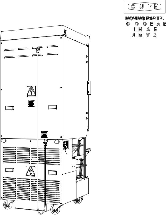
Label is located on the rear access panel and applies to each of the drum motor and accumulator assemblies within the enclosure.
CAUTION, MOVING PARTS.
DO NOT OPERATE WITH PANEL
REMOVED
Label is located on Top Cover and Rear Access
Panels.
INDICATES HAZARDOUS VOLTAGE
WITHIN
Label is located near Power Cord inlet.
CAUTION, RISK OF ELECTRIC SHOCK.
DISCONNECT POWER BEFORE
SERVICING UNIT.
Copyright © 2011 Automated Equipment LLC All rights reserved. |
5 |

RAM™ 280-F Frozen Fry Dispenser
Dispenser Assembly (Models prior to s/n 28FR0802B0249)
Note: Before assembling the Dispenser it is recommended that all parts be cleaned, sanitized, dry, and handled in a sanitary manner. Refer to the Cleaning Procedures (Page 12) for more information.
Open the cabinet door. Install the left and right flap door assemblies as shown above.
Accumulator Motor shaft with Chuck
Accumulator
Door
Accumulator
Housing
Accumulator
Doors
Accumulator Door Assembly |
Accumulator Housing Assembly |
Install the left and right Accumulator Doors by first inserting the rear of the doors onto the Accumulator Motor Shafts, then slide the Chucks forward and rotate the chucks clockwise until finger-tight. Install the left and right Accumulator Housings over the Accumulator Doors.
6 |
Copyright © 2011 Automated Equipment LLC All rights reserved. |
RAM™ 280-F Frozen Fry Dispenser
Dispenser Assembly Cont.
Note: Accumulator Housings, Drums, and Fry Diverters are universal to left, and right, positions within the cabinet. The Hoppers are NOT universal to the left, and right, positions within the cabinet.
Fry |
Hopper |
|
|
Diverter |
|
Hopper
Drum
Fry Diverter Assembly |
Drum and Hopper Assembly |
Install the Fry Diverters in the Hoppers by sliding the Fry Diverters into the slot located on the inside Hopper walls. Install Drums into the Hoppers making sure the square opening in the drum is pointed to the rear of the Hopper. Repeat assembly for left and right hopper. Install the hopper assemblies into the cabinet by sliding them onto the hopper supports. DO NOT force the drum on to the shaft. Rotate the drum in the hopper until the square opening meshes with the drum motor shaft, then slide the hopper assembly back until it drops into place.
Drip Tray
Basket
Trays
Basket Tray Assembly |
Drip Tray assembly |
Once the Accumulator Housings and Hopper Assemblies are in place, close the Cabinet Door. Assemble Basket Tray and Drip Tray to lower dispensing area. Basket Trays are not universal to the left and right positions.
Copyright © 2011 Automated Equipment LLC All rights reserved. |
7 |
RAM™ 280-F Frozen Fry Dispenser
Using the Hash-brown Rack
The RAM 280-F cabinet can be used to store frozen hash-browns while serving breakfast. To use the cabinet for hash-brown storage, properly assemble the dispenser (pages 6-11), then install the hashbrown rack accessory as shown in the diagram below. The rack will serve as a shelf inside the refrigerated cabinet for hash-brown storage.
Note: The hash-brown racks should be removed during normal operation.
Caution: Do not store hash-browns on the drum below the rack, this can damage the dispenser.
Insert the four rods of the hash-brown rack into the holes in the side of the hopper then lower the rack onto the fry diverter.
Hash-brown rack PN: 293966 (shown with Hopper PN: 293139)
Hash-brown rack installation
8 |
Copyright © 2011 Automated Equipment LLC All rights reserved. |
RAM™ 280-F Frozen Fry Dispenser
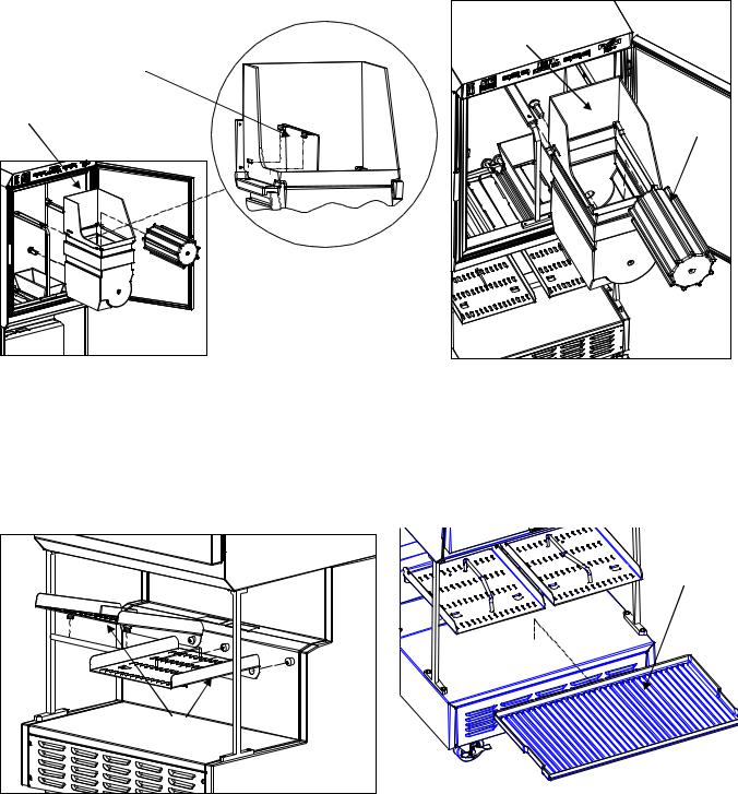
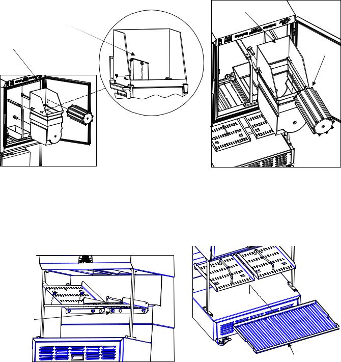
Dispenser Assembly (Models after and including s/n 28FR0802B0249)
Note: Before assembling the Dispenser it is recommended that all parts be cleaned, sanitized, dry, and handled in a sanitary manner. Refer to the Cleaning Procedures (page 12) for more information.
Pivot Block
Open the cabinet door. Accumulator doors are pre-installed. Install the left and right flap doors by slipping them under the accumulator doors and seating the pivot pin into the plastic pivot blocks, as shown above. (Accumulator Doors are hidden for clarity in Right Hand view).
Accumulator Housing Assembly
Install the left and right Accumulator Housings over the Accumulator Doors.
Copyright © 2011 Automated Equipment LLC All rights reserved. |
9 |
RAM™ 280-F Frozen Fry Dispenser
Dispenser Assembly Cont.
Note: Accumulator Housings, Drums, and Fry Diverters are universal to left, and right, positions within the cabinet. The Hoppers and Basket trays are NOT universal to the left, and right, positions of the cabinet.
|
] |
Fry |
Hopper |
|
|
Diverter |
|
Hopper |
Drum |
|
|
Fry Diverter Assembly |
Drum and Hopper Assembly |
Install the Fry Diverters in the Hoppers by sliding the Fry Diverter tabs into the slots located on the inside Hopper walls. Install Drums into the Hoppers making sure the square opening in the drum is pointed toward the rear of the Hopper. Repeat assembly for left and right hoppers. Install the hopper assemblies into the cabinet by sliding them onto the hopper supports. DO NOT force the drum on to the shaft. Rotate the drum in the hopper until the square opening meshes with the drum motor shaft, then slide the hopper assembly backward until it drops into place.
Left
Basket
Tray 
Right
Basket
Tray
Drip Tray
Basket Tray Assembly |
Drip Tray assembly |
Once the Accumulator Housings and Hopper Assemblies are in place, close the Cabinet Door. Assemble Basket Tray and Drip Tray to lower dispensing area. Basket Trays are not universal to the left and right positions.
10 |
Copyright © 2011 Automated Equipment LLC All rights reserved. |

RAM™ 280-F Frozen Fry Dispenser
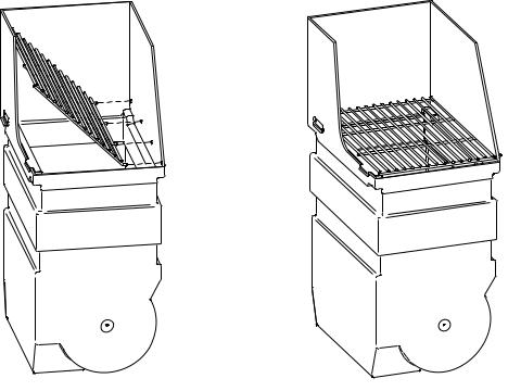
Using the Hash-brown Rack
The RAM 280-F cabinet can be used to store frozen hash-browns while serving breakfast. To use the cabinet for hash-brown storage, properly assemble the dispenser (pages 9-11), then install the hashbrown rack accessory as shown in the diagram below. The rack will serve as a shelf inside the refrigerated cabinet for hash-brown storage.
Note: The hash-brown racks should be removed during fry dispensing.
Caution: Do not store hash-browns on the drum below the rack, this can damage the dispenser.
Insert the four rods of the hash-brown rack into the holes in the side of the hopper then lower the rack onto the fry diverter.
Hash-brown rack
PN: 293966 (shown with Hopper p/n 294396)
Hash-brown rack installation
Copyright © 2011 Automated Equipment LLC All rights reserved. |
11 |

RAM™ 280-F Frozen Fry Dispenser
Disassembly, Defrost & Cleaning
IMPORTANT! These cleaning instructions are intended as a guide. Refer to your local, state, and federal regulations for any additional instructions and for cleaning frequency requirements.
Remove all Baskets from the dispense area. Open the Cabinet Door and remove the left and right Hopper Assemblies by lifting the front of the Hopper up slightly and pulling forward on assembly.
Remove any unused product from the Hoppers and Accumulator Housings by emptying the product into an approved storage container. Place the storage container immediately into a freezer to maintain frozen product.
Defrost
Because the dispenser employs a cold wall design, it will be necessary to manually defrost the cabinet daily. After removing the product, using the On/Off Switch turn the power OFF and unplug the dispenser power cord. Open the Cabinet Door and allow 1 hour to defrost.
Note: Failure to turn the dispenser power off prior to defrosting the cabinet may result in a cabinet over-temperature error. (Error -5-).
Caution: Never use a sharp object to remove frost build-up. Never drill or otherwise puncture cabinet walls or top.
Lift and remove the Accumulator Housings.
For dispensers with removable accumulator doors: remove the Accumulator Doors by rotating the chucks Counter-Clockwise until unlocked, then pull the accumulator doors forward.
Take the removable components from the Dispenser to the washing area. Wash them with a hot solution of detergent and water. Rinse each component with clear water and sanitize (wash/rinse/sanitize) (HCS). Allow components to air dry,.
NOTE: The removable components are NOT dishwasher safe.
Move the Dispenser out from the wall to clean behind and underneath it.
Do NOT roll the dispenser to the back sink for cleaning, this will cause unnecessary wear on the dispenser.
Once the cabinet is free of frost, wipe down the internal and external cabinet with a hot solution of detergent and water. Rinse with clear water and repeat wipe down with sanitizing solution (HCS) and allow to air dry.
Warning: Do not spray the Dispenser with Liquid or Solvents. The Dispenser does not provide a water tight seal. Contaminants and moisture may get into sensitive components.
Dry all components and reassemble the Dispenser (page 6-11). Move Dispenser back into place.
Notice: The dispenser must be accessible from all sides for routine cleaning and maintenance. A minimum of 0.5” (13 mm) clearance on both sides and 2” (50 mm) behind the dispenser is recommended.
Lift and remove left and right Flap door assemblies.
Remove left and right Basket Guide assemblies from the Dispenser by lifting up on the front of the guide until it unlatches, then pull outward and upward. Remove Drip Tray by lifting, tilting and sliding forward.
12 |
Copyright © 2011 Automated Equipment LLC All rights reserved. |

RAM™ 280-F Frozen Fry Dispenser
Dispenser Startup
Make sure Power Switch, located on the left portion of the operator panel, is turned off. Assemble the Dispenser (Pages 6-11). Plug the Power Cord into an approved outlet and turn the Dispenser on.
Note: Turn Dispenser on a minimum of 90 minutes (depending on ambient temperature conditions) before loading frozen product into the Dispenser. Once the temperature display has dropped to 10°F (-12°C) load frozen product into Dispenser and use the Dispenser.
Power Switch |
Display |
|
|
|
Power Light |
|
|
||||
|
|
|
|
|
|
|
|
|
|
|
|
Basket Size |
|
|
Basket Size |
||
Buttons |
|
|
|
|
Buttons |
Small loads |
|
|
Up Button |
||
Medium loads |
|
|
Enter Button |
||
Large loads |
|
|
Down Button |
||
|
|||||
The Operator Panel consists of a Power Switch and three groups of controls: the Left Hopper controls, center System controls with Data Display, and the Right Hopper controls. Each Hopper is controlled as if it were an independent dispenser.
On power up, the display will very briefly show the Software Name, Software Version, Copyright Notice, and then the Main Screen (typically the dispenser temperature). The Dispenser will NOT respond to keypad selections before the Main Screen is displayed.
The Main Screen will appear as shown above. The number displayed in the center represents the interior cabinet temperature.
The operator panel is used to make basket load size selections and to access controller functions.
Note: |
The Managers Menu and Diagnostic Menu may require a manager’s password to |
|
access the Functions. By Default these Passwords are disabled. |
•Use the Up  and Down
  Arrow Buttons to access a desired function. (See pages 18-22 for a complete list of functions and their descriptions.)
•Press the Enter  Button to select the desired function.
•Basket Size Buttons also function as numbers:
(e.g. Left Small=1, Left Medium=2, Left Large=3, Right Small=4, Right Medium=5, Right Large=6)
Copyright © 2011 Automated Equipment LLC All rights reserved. |
13 |
 Loading...