

Page 1
RPT-37PB3F
Sensors
Phototransistor, top view type
RPT-37PB3F
The RPT-37PB3F is a silicon planar phototransistor. Since it is molded in plastic with a visible light filter, there is almost no
effect from stray light. It is particularly suited for use with a ROHM SIR-34ST3F infrared light emitting diode.
It is possible to distinguish the polarity by the shape of ramp type.
!!!!Applications
Optical control equipment
Receiver for sensors
!!!!Features
1) High sensitivity.
2) Almost no effect from stray light.
!!!!Absolute maximum ratings (Ta = 25°C)
Parameter Symbol
Collector-emitter voltage
Emitter-collector voltage
Collector current
Collector power dissipation
Operating temperature
Storage temperature
V
CEO
V
ECO
I
C
P
Topr
Tstg
C
!!!!Electrical and optical characteristics (Ta = 25°C)
Parameter Symbol
Light current
Dark current
Peak sensitivity wavelength
Collector-emitter saturation voltage
Half-angle
Response time
V
I
CE(sat)
θ
I
CEO
λ
1 / 2
tr·t
Min.
C
2.0
−
P
−
−
−
f
−
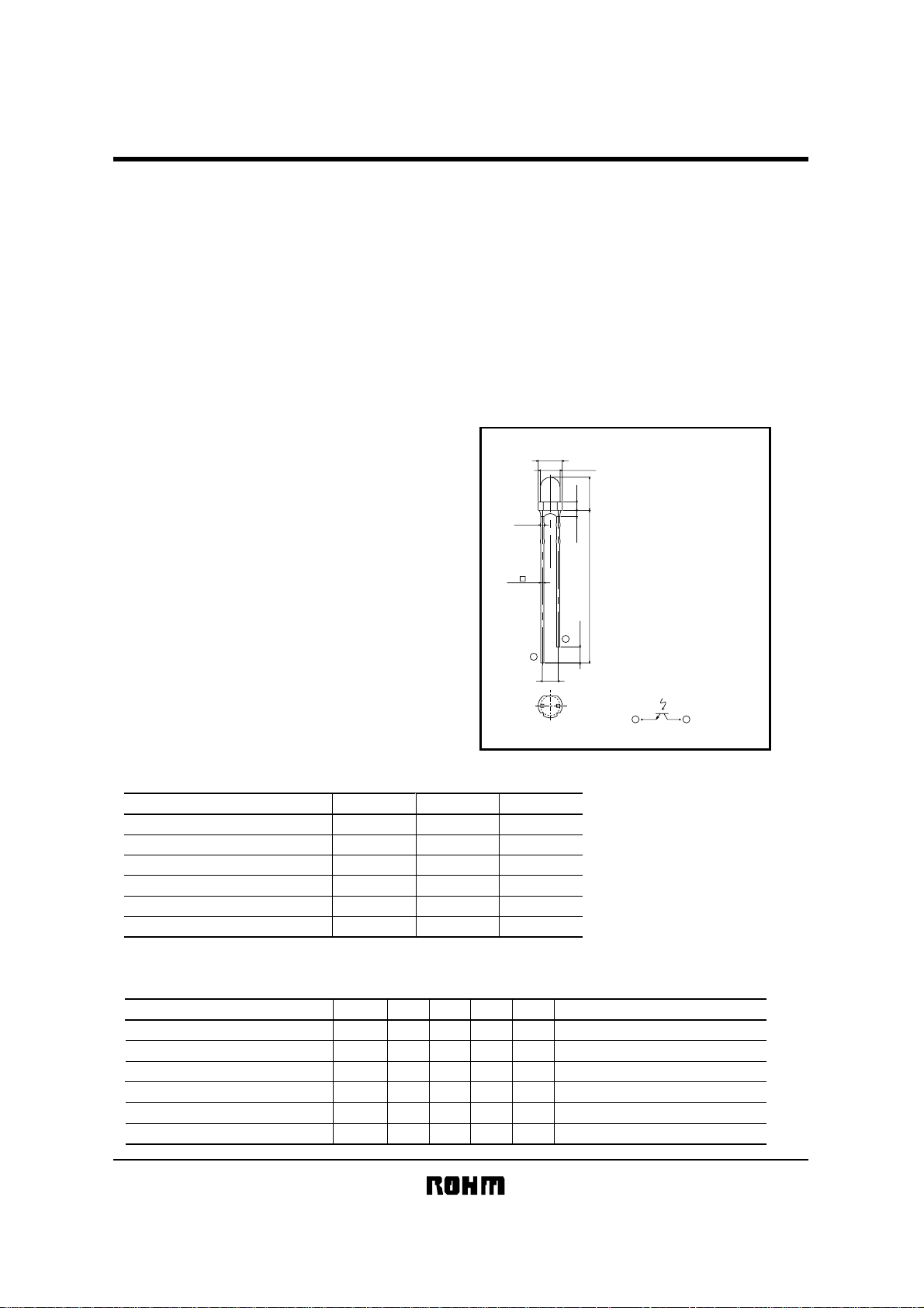
!!!!External dimensions (Units : mm)
φ3.8±0.3
φ3.1±0.2
1.3Max.1
5.2±0.3Min.24
4−0.6
2− 0.5
2
2.5±1
1
(2.5)
Limits
32
5
30
150
−25~+85
−30~+100
Typ.
−
−
800
−
±36
10
Max.
0.5
0.4
Unit
V
V
mA
mW
°C
°C
Unit
−
mA V
µA
nm
−
V
deg
−
µs
−
CE
=5V, E=500L
VCE=10V(Black box)
C
=1mA, E=500L
I
CC
=5V, IC=1mA, RL=100Ω
V
Notes :
1. Unspecfied tolerance shall be ±0.2.
2. Measurement in the bracket are that of
lead pin at base the mold.
3. Dimension in parenthesis are show for
reference.
Internal connection diagram
1
Emitter Collector
Conditions
2
X
−
X
−
1/2
Page 2
RPT-37PB3F
Sensors
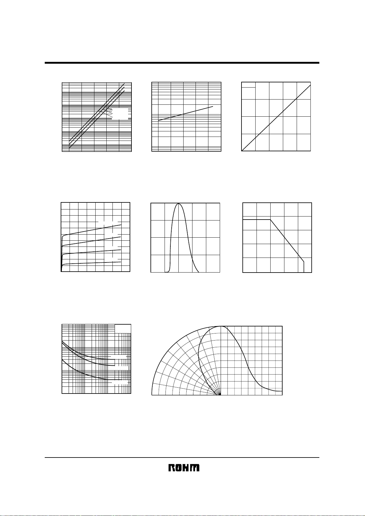
!!!!Electrical and optical characteristic curves
1000
(nA)
100
CEO
10
1
DARK CURRENT : I
0.1
AMBIENT TEMPERATURE : Ta
Fig.1 Dark current
vs. ambient temperature
10
8
(mA)
C
6
4
LIGHT CURRENT : I
2
0
COLLECTOR−EMITTER VOLTAGE : V
E=1000Lux
Fig.4 Output characteristics
1000
(µs)
r
100
10
RESPONSE TIME : t
1
0.1 110
COLLECTOR CURRENT : I
Fig.7 Response time vs.
collector current
750Lux
500Lux
250Lux
VCE=10V
CE
=20V
V
CE
=30V
V
(°C)
CE
Ta=25°C
VCE=5V
RL=1kΩ
RL=500Ω
RL=100Ω
C
(mA)
(V)
1000
500
(%)
C
200
100
50
20
RELATIVE LIGHT CURRENT : I
10
100−25 0 25 50 75
−25 75 10050250
AMBIENT TEMPERATURE : Ta
Fig.2 Relative output
100
(%)
C
75
50
25
RELATIVE SENSITIVITY : I
1602468101214
0
OPTICAL WAVELENGTH : λ (nm)
Fig.5 Spectral sensitivity
60°
70°
80°
90°
100 80 60 40 20
RELATIVE LUMINOUS INTENSITY (%)
(°C)
vs. ambient temperature
600400 800 1000 1200 1600
10°
20°
30°
40°
50°
Fig.8 Directional pattern
0
8
VCE=5V
6
(mA)
C
4
2
LIGHT CURRENT : I
0 250 500 750 12501000
ILLUMINANCE : E (Lx)
Fig.3 Light current vs. irradiance
(mW)
160
C
120
80
40
COLLECTOR DISSIPATION : P
0
−25 0 25 50 75 100
AMBIENT TEMPERATURE : Ta (°C)
Fig.6 Collector dissipation vs.
ambient temperature
10°0°20° 30° 40° 50° 60° 70° 80° 90°
ANGULAR DISPLACEMENT (deg)
100
80
60
40
20
RELATIVE LUMINOUS INTENSITY (%)
2/2
 Loading...