

Page 1
RPI-222
Sensors
Photointerrupter, double-layer mold type
RPI-222
The RPI-222 is an ultra-small size, double-layer mold photointerrupter.
!!!!Application
Optical control equipment
Cameras
Floppy disk drives
Digital video disc
!!!!Features
1) Ultra-small.
2) Minimal influence from stray light.
3) Low collector-emitter saturation voltage.
!!!!
Absolute maximum ratings
Parameter
Forward current
Input
(LED)
Reverse voltage
Power dissipation
Collector-emitter voltage
Output
(Photo transistor)
Emitter-collector voltage
Collector current
Collector power dissipation
Operating temperature
Storage temperature
(Ta=25°C)
Symbol
F
I
V
R
P
D
V
CEO
V
ECO
I
C
P
C
Topr
Tstg
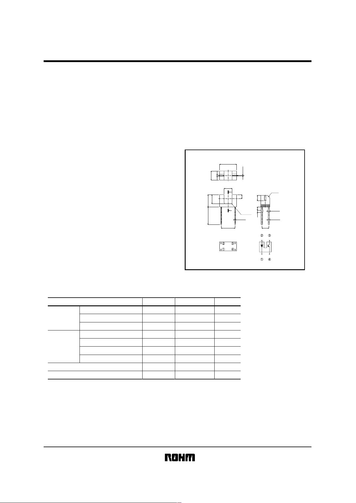
!!!!External dimensions (Units : mm)
Limits
50
5
80
30
4.5
30
80
−25∼+85
−30∼+85
3.3
Min.5
4.9±0.3
2.6
(0.4)
Gap
2.0±0.3
A
2.3
A'
(4)
Unit
mA
V
mW
V
V
mA
mW
˚C
˚C
Notes :
1. Unspecified tolerance
shall be ±0.2.
(0.2)
2. Dimension in parenthesis are
show for reference.
1
(1.5)
Optical axis center
2-R0.3
2−0.2
Anode Collector
Cathode Emitter
0.5 1
C0.7
2−0.5
2−0.4
(2)
Page 2
Sensors
!!!!Electrical and optical characteristics (Ta=25°C)
Parameter
Input
characteristics
Output
characteristics
Forward voltage
Reverse current
Dark current
Peak sensitivity wavelength
Collector current
Transfer
characteristics
Collector-emitter saturation voltage
Response time
!!!!
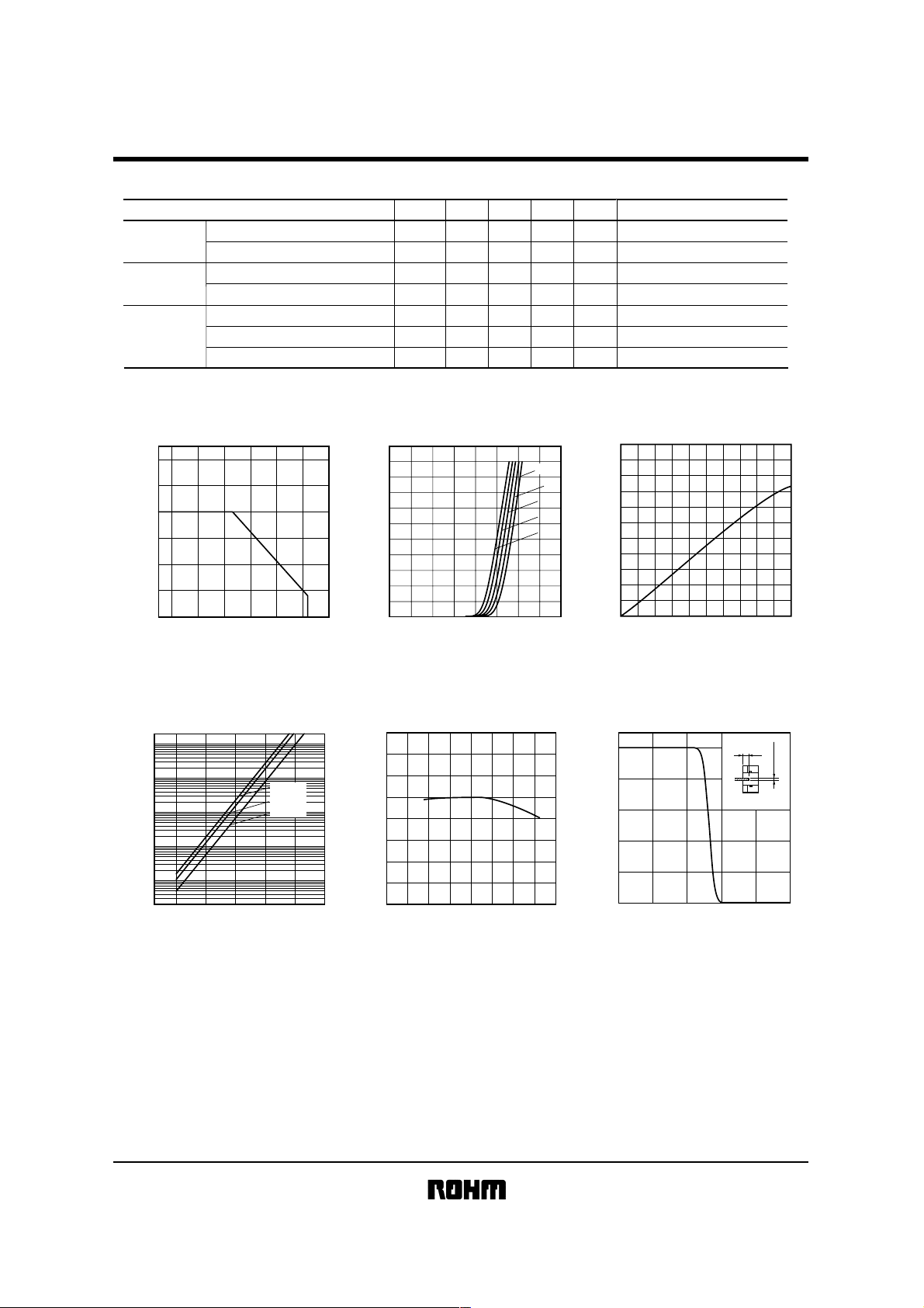
Electrical and optical characteristic curves
Symbol
RPI-222
Min.
Typ.
Max.
Unit
F
−
−
−
−
0.18
−
−
1.3
−
−
800
0.3
−
10 −
1.6
10
0.5
−
0.95
0.4
V
IR
ICEO
λP
IC
CE
(sat)
V
tr·tf
F=
VI
V
µA
V
µA
nm
−
V
mA
IF=
V
V
µs
50mA
R=
5V
CE=
10V
CE=
5V,
20mA,
CC=
5V,
Conditions
I
F=
10mA
IC=
0.1mA
F=
I
20mA,
L=
R
100Ω
120
(mW)
C
/P
D
100
P
DPC
80
60
40
20
0
−20 0 20
AMBIENT TEMPERATURE : Ta (˚C)
POWER DISSIPATION /
COLLECTOR POWER DISSIPATION : P
40 60 80 100
Fig.1 Power dissipation / collector power
dissipation vs. ambient temperature
1000
100
(nA)
CEO
10
1
DARK CURRENT : I
0.1
−25 0 25 50 75 100
AMBIENT TEMPERATURE : Ta
VCE=30V
VCE=20V
VCE=10V
(°C)
Fig.4 Dark current vs. ambient
temperature
50
(mA)
F
40
30
20
10
FORWARD CURRENT : I
0
0.4 0.6 0.80.2 1.0 1.2 1.4 1.6 1.8
FORWARD VOLTAGE : V
Fig.2 Forward current
160
(%)
C
140
120
100
80
60
40
20
RELATIVE COLLECTOR CURRENT : I
0
−40 −20 0 20406080100
AMBIENT TEMPERATURE : Ta
Fig.5 Relative output vs. ambient
temperature
F
(V)
vs. forward voltage
(°C)
−25˚C
0˚C
25˚C
50˚C
75˚C
2.0
(mA)
C
1.0
COLLECTOR CURRENT : I
0
0403010 20 50
FORWARD CURRENT : I
Fig.3 Collector current
(%)
100
C
80
60
40
20
RELATIVE COLLECTOR CURRENT : I
0
0.50 1.0 1.5 2.0 2.5
DISTANCE : d (mm)
Fig.6 Relative output current
vs. distance ( Ι )
F
(mA)
vs. forward current
d
mm
t=0.6
Page 3

Sensors
(%)
100
C
80
60
40
20
RELATIVE COLLECTOR CURRENT : I
0
0.50 1.0 1.5 2.0 2.5
DISTANCE : d
Fig.7 Relative output current
vs. distance ( ΙΙ )
3.0
(mA)
C
1.5
COLLECTOR CURRENT : I
0
COLLECTOR−EMITTER VOLTAGE : V
Fig.10 Output characteristics
(mm)
4861020
t=0.6
IF=50mA
mm
40mA
30mA
20mA
10mA
d
CE
(V)
1000
(µs)
f
,t
100
r
10
RELATIVE TIME : t
1
COLLECTOR CURRENT : I
Ta=25°C
CC
V
RL=1kΩ
RL=500Ω
RL=100Ω
C
(mA)
=5V
Fig.8 Response time
vs. output current
V
CC
Input
Input
Output
R
L
Output
t
d
t
r
t
d
: Delay time
t
r
: Rise time (time for output current to rise
from 10% to 90% of peak current)
t
f
: Fall time (time for output current to fall
from 90% to 10% of peak current)
Fig.11 Response time mesurement circuit
1000.1 1 10
90%
10%
t
f
RPI-222
50
(mA)
F
40
30
20
10
FORWARD CURRENT : I
0
−20 0 20 40 60 80 100
AMBIENT TEMPERATURE : Ta (°C)
Fig.9 Forward current falloff
 Loading...