

Page 1
22-306.fm Page 1 Friday, August 6, 1999 12:19 PM
OWNER’S MANUAL
Please read before using this equipment.
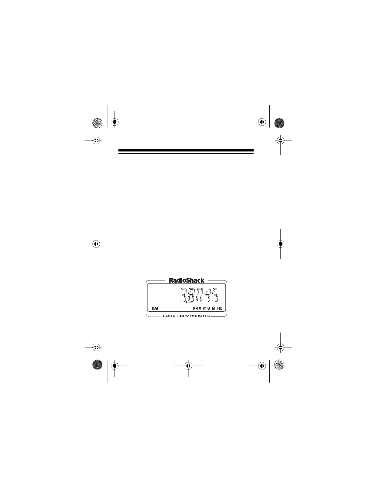
LCD RF Frequency Counter
Cat. No. 22-306
Page 2
22-306.fm Page 2 Friday, August 6, 1999 12:19 PM
FEATURES
Your RadioShack LCD RF Frequency Counter is a microcomputer-based instrument that accurately measures radio frequency (RF) or logic frequency signals.
It is ideal for the home electronic hob byist or a small repair shop. Use it to measure cordless telephone, ham,
CB radio, radio-controlled toy remotes, radio/TV circuits, or digital instrument frequencies.
Your counter can measure RF signals within a 1 MHz–
1.3 GHz range or logic frequency signals within a
0 Hz–10 MHz range. You can display the frequency
with different resolutions and update rates.
The counter’s features include:
Selectable Measurement Gate Times
— let you
choose a fast setting for quick measurement updates
or a slow setting for maxim um resolution.
Selectable Input Impedance
— lets you select 50ohm impedance (for use with the supplied antenna or
an optional 50-ohm coaxial cable) or high input impedance (for use with an opti onal high-impedance probe).
©
1997 Tandy Corporation.
RadioShack is a registered trademark used by Tandy Corporation.
All Rights Reserved.
2
Page 3

22-306.fm Page 3 Friday, August 6, 1999 12:19 PM
Selectable Input Frequency Range — you can
choose between 1 MHz and 50 MHz or between 50
MHz and 1.3 GHz for RF, or between 0 Hz and 10 MHz
for logic frequency.
BNC Connector — lets you connect the supplied antenna to measure through-air RF signals, or a cable
with a male BNC connector (not supplied) for direct frequency measurements.
Backlight — makes the display easy to see in low-light
conditions.
Hold — freezes the data on the display.
Recharging Circuit — lets you recharge nickel- cad-
mium batteries while they are installed in the counter.
You need four AA batteries or an AC adapter to use
this counter (see “Connecting Power” on Page 5).
3
Page 4

22-306.fm Page 4 Friday, August 6, 1999 12:19 PM
CONTENTS
Preparation ............................................................. 5
Connecting the Ant enna ..... .. ............................ 5
Connecting Power ............................................. 5
Using Batteries .......................................... 6
Recharging Nickel- C adm ium Batteries ...... 9
Using AC Power ....................................... 11
Connecting an Optional Coaxial Cable ........... 13
Operation .............................................................. 14
Turning On/Off the Counter ............................. 14
Setting the Input Impedance ........................... 14
Setting the Frequency Range ......................... 15
Setting the Gate Speed ................................... 16
Using the Backlight ......................................... 18
Using Hold ....................................................... 18
Measuring Frequencies ....... .. .......................... 19
Care and Maintenance ......................................... 23
Specifications ....................................................... 25
Ty pical Input Sensitivity .................. ................. 28
4
Page 5
22-306.fm Page 5 Friday, August 6, 1999 12:19 PM
PREPARATION
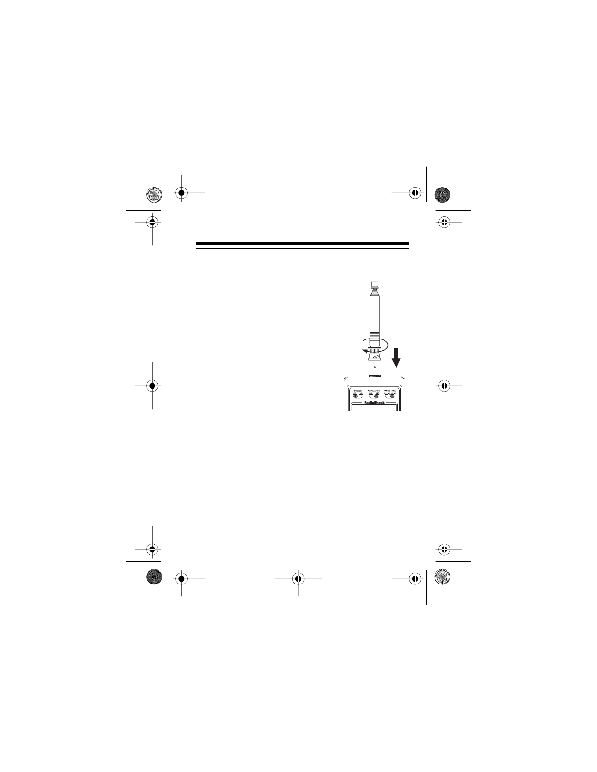
CONNECTING THE ANTENNA
To connect the supplied antenna to
the connector, place it over the connector on top of the counter and
align the r ecess on the antenna with
the two tabs on t he connector. Then
slightly push down on the antenna’s
connector and turn it clockwise until
it locks.
Note:
You can also connect an antenna (not supplied) that is tuned to
the frequency band of the signal
you want to measure.
CONNECTING POWER
You can power your counter from four AA batteries (alkaline or rechargeable nickel-cadmium) or from a standard AC outlet using an AC adapter ( not supplied).
5
Page 6

22-306.fm Page 6 Friday, August 6, 1999 12:19 PM
Using Batteries
Your counter can use four AA batteries (not supplied)
for power. We recommend alkaline batteries, such as
RadioShack Cat. No. 23-552. You can also use rechargeable nickel-cadmium batteries, such as Cat. No.
23-125.
Cautions:
• Only use fresh batteries of the required size and
type.
• Do not mix old and new bat teries, different types of
batteries (standard, alkaline, or rechargeable), or
rechargeable batteries of different capacities.
6
Page 7
22-306.fm Page 7 Friday, August 6, 1999 12:19 PM
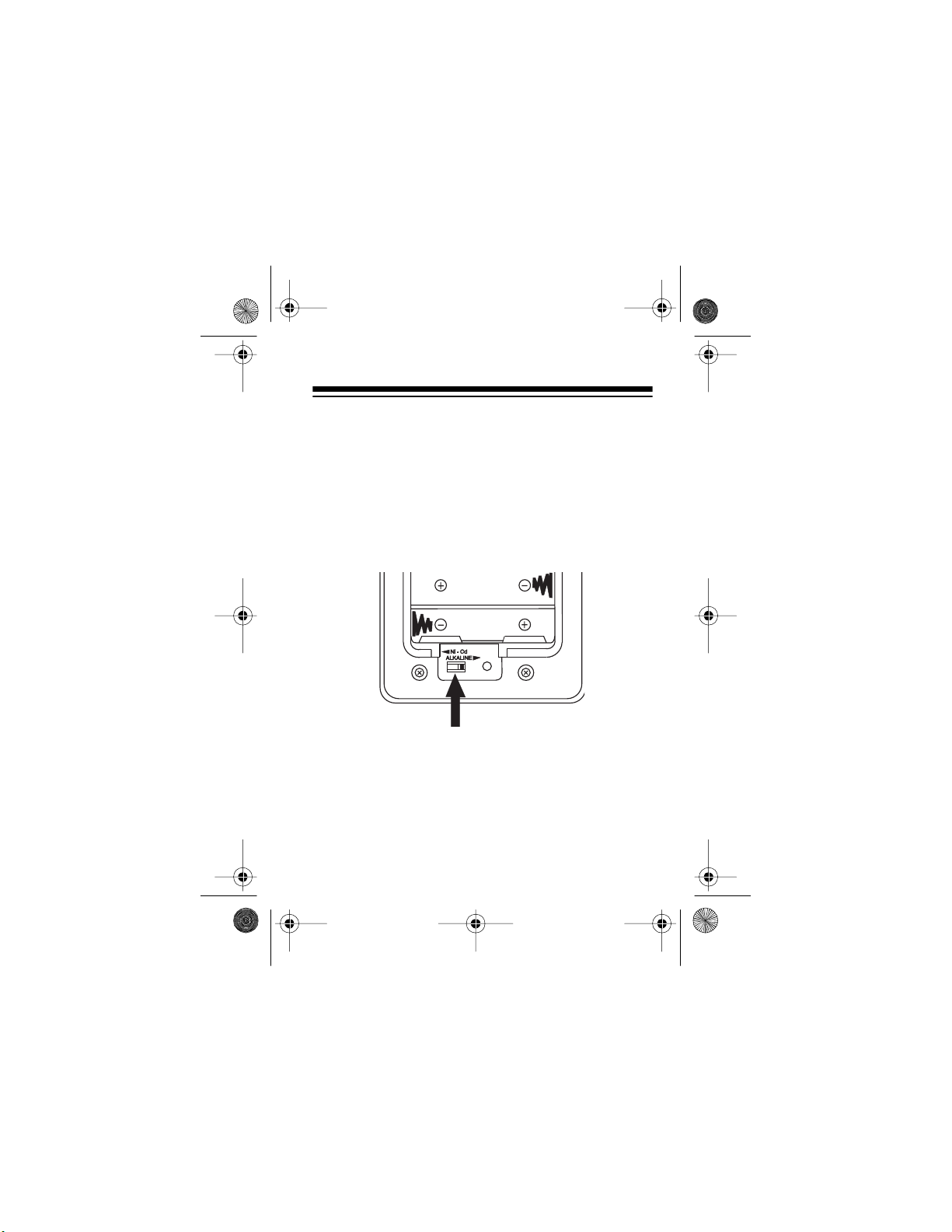
Follow these steps to install batteries into the counter.
1. Use a Phillips screwdriver to loosen the screw on
the counter’s battery compartment cover. Then
remove the co ver.
2. Using a small screwdriver , set the counter’s battery
type switch to the appropriate position —
LINE
for alkaline batteries or
Ni-Cd
for recharge-
ALKA-
able nickel-cadmium batteries.
3. Put the batteries in the compartment as indicated
by the polarity symbols (+ and –) marked inside.
7
Page 8
22-306.fm Page 8 Friday, August 6, 1999 12:19 PM
Warning: If you use alkaline or other nonrechargeable batteries, do not connect the AC
adapter to the counter with the battery type switch
set to
. Doing so activates the counter’s
Ni-Cd
charging circuit. Trying to charge non-rechargeable batteries can cause the batteries to leak or
explode, possibly causing personal injury.
4. Replace the battery compartment cover, then
tighten the screw to secure the cover.
When the battery voltage becomes too low, or there is
a low AC voltage condition,
appears on the low-
BATT
er left corner of the display and the counter might display incorrect measurements. If
BATT
appears,
replace or recharge the batteries or check the AC connection.
To ensure consistent operation, replace alk ali ne batteries at least every 12 m onths.
8
Page 9

22-306.fm Page 9 Friday, August 6, 1999 12:19 PM
Recharging Nickel-Cadmium Batteries
To recharge nickel -cadmium batteri es, you need an AC
adapter (such as Cat. No. 273-1455) (see “Using AC
Power” on Page 11).
Warning:
Do not try to recharge alkaline or other non-
rechargeable bat ter ies. They might rupture or explode.
Follow these steps to recharge nickel-cadmium batteries while they are inside the counter.
1. Be sure the bat ter y type switch is set to
2. Plug the AC adapter’s barrel plug into the
Ni-Cd
.
DC 9V
jack on the left side of the counter.
3. Plug the other end of the adapter into a standard
AC outlet.
4. Charge the bat teries for 12 to 14 hours.
Caution:
Charging batteries for longer than the
recommended time can damage them.
5. Unplug the adapter from the AC outlet first. Then
unplug it from the
DC 9V
jack.
9
Page 10

22-306 .fm Page 10 Friday, August 6, 1999 12:19 PM
Note: Occasionally, fully discharge nickel-cadmium
batteries before you recharge them. Otherwise, the
batteries lose their ability to fully charge.
Important: Your counter can use rechargeable nickelcadmium batteries. At the end of a battery’s useful life,
it must be recycled or disposed of properly. Contact
your local, county, or state hazardous waste management authorities for information on recycling or disposal
programs in your area. Some options that might be
available are: municipal curbside collection, drop-off
boxes at retailers such as your loc al Radi oShack store,
recycling collection centers, and mail-back programs.
10
Page 11

22-306 .fm Page 11 Friday, August 6, 1999 12:19 PM
Using AC Power
You can power your counter from a standard AC outlet
using a 9-volt AC adapter (not supplied), such as Cat.
No. 273-1455.
Cautions:
• Use onl y an AC adapter that supplie s 9 volts, delivers at least 300 milliamps, and has a center negative plug that properly fi ts the counter’s
The recommended adapter meets these specifications. Using an adapter that does not meet these
specifications could damage the counter and the
adapter.
• Always plug the AC adapter into the counter
before you plug it into the AC outle t. Always unplug
the AC adapter from the AC outlet before you
unplug it from the counter.
DC 9V
jack.
11
Page 12

22-306 .fm Page 12 Friday, August 6, 1999 12:19 PM
1. Insert the adapter’s barrel plug into the
DC 9V
on the left side of the counter.
2. Plug the adapter’s other end into a standard AC
outlet.
12
jack
Page 13

22-306 .fm Page 13 Friday, August 6, 1999 12:19 PM
CONNECTING AN OPTIONAL
COAXIAL CABLE
If you want to measure RF frequencies directly, or a
logic freque ncy, connect a 50 -ohm coaxial cable ( or oscilloscope probe) with a male BNC connector from the
device to the counter ’s connector.
13
Page 14

22-306 .fm Page 14 Friday, August 6, 1999 12:19 PM
OPERATION
TURNING ON/OFF THE COUNTER
To turn on/off the counter, set
appropriate position.
POWER OFF/ ON
to the
SETTING THE INPUT IMPEDANCE
To test RF frequencies, set
connected the supplied antenna or an optional 50-ohm
coaxial cable.
14
IMPEDANCE
to 50 W if you
Page 15

22-306 .fm Page 15 Friday, August 6, 1999 12:19 PM
IMPEDANCE
Set
HiZ
to
if you connected an optional
high-impedance probe, such as an oscillo scope probe.
Note:
mode (when
The
IMPEDANCE
RANGE
is set to
switch is disabled in the logic
0–10
).
SETTING THE FREQUENCY
RANGE
To ensure accurate measurements, set
proper position for the frequency you want to measure.
1–50
— to measure RF between 1 MHz and 50 MHz.
50–1.3G
— to measure RF between 50 MHz and 1.3
GHz.
RANGE
to the
15
Page 16

22-306 .fm Page 16 Friday, August 6, 1999 12:19 PM
0–10
— to measure logic frequencies between 0 Hz
and 10 MHz. (The input must be a TTL/CMOS circuit
output.)
Note:
If the measured frequency is outside the
counter’s set range, the reading will be inaccurate.
SETTING THE GATE SPEED
In the RF test mode (with
1.3G
), you can choose between two gate speeds: 64
RANGE
set to
1–50
or
50–
mS and 640 mS. The 64 mS gate speed updates the
display every 128 milliseconds, but the resolution is
lower than at 640 mS. The 640 mS gate speed updates
the display only once every 1.28 seconds, but provides
the maximum display resolution (the least significant
digit is in units of 100 Hz).
In the logic input mode (with
RANGE
set to
0–10
), you
can choose between two gate speeds: 1 S and 10 S.
The 1 S gate speed updates the display every 2 seconds, but the resolution is lower than at 10 S. The 10 S
gate speed updates the display only once every 20
seconds, but provides the maximum display resolution
(the least significant digit is in units of 0.1 Hz).
16
Page 17

22-306 .fm Page 17 Friday, August 6, 1999 12:19 PM
GATE SPEED
Press
to toggle between the 64 mS and
640 mS gate speed for RF, or between the 1 S and 10
S gate speed for logic measurements.
17
Page 18

22-306 .fm Page 18 Friday, August 6, 1999 12:19 PM
USING THE BACKLIGHT
The counter’s display has a backlight to help you see
the display in low light conditions. To turn on the backlight, press
about 5 seconds.
LIGHT/HOLD
. The backlight stays on for
USING HOLD
HOLD freezes the data on the display.
To turn on HOLD, press
light on, then press it again.
data stays on the display until HOLD is released.
18
LIGHT/HOLD
to turn the back-
appears and the
HOLD
Page 19

22-306 .fm Page 19 Friday, August 6, 1999 12:19 PM
To release HOLD, just press
disappears.
Note:
You cannot use the backlight without turning off
HOLD.
LIGHT/HOLD
again.
HOLD
MEASURING FREQUENCIES
Once you have turned on the counter and set the frequency range, input impedance, and gate speed, do
the following to measure frequencies.
If you connected an antenna, fully extend the antenna
and be sure
the device whose frequency you want to measure.
Caution:
tenna of the device under test. Doing so might exceed
the power or voltage rating of the counter and could
damage the counter and the device.
IMPEDANCE
Do not let the counter ’s antenna touch the an-
is set to 50 W. Then turn on
19
Page 20

22-306 .fm Page 20 Friday, August 6, 1999 12:19 PM
For example, to check the frequency of a channel on a
CB radio, turn on the CB, then select a channel and
press the CB’s talk but ton. The counter’s display shows
what frequency th e CB is tr ansmitting on.
You can measure an RF or a logic frequency using an
oscillosc ope or other high-im pedance inp ut probe if you
have connected the device’s cable as explained in
“Connecting an Optional Coaxial Cable” on Page 13.
Be sure
IMPEDANCE
on the counter is set to
HiZ
, then
turn on the device.
Caution:
The RF signal you are measuring should not
exceed 1.4V peak-to-peak. The logic frequency signal
you are measuring must be a TTL level output. Measuring signals with a higher voltage could damage the
counter.
Notes:
IMPEDANCE
•The
mode when
switch is only activated in the RF
RANGE
is set to
1–50
or
50–1.3G
.
• In the logic mode with the gate speed set to 10 S,
if the measured frequency is over range (higher
than 9.9999999 MH z), the display shows
.
--.-
--- OF
20
Page 21

22-306 .fm Page 21 Friday, August 6, 1999 12:19 PM
When you measure RF, you might see occasional random readings on the display. The counter has special
“anti-oscillation” detection routines that detect random
values and zero the display if the microprocessor detects more than four counts, each of which differs more
than 50 kHz from the previous count. For example:
Count
(MHz)
19.5500 19.5500
18.7800 770 18.7800
18.8400 60 18.8400
18.7000 140 18.7000
20.1500 1450 0.0000
Difference
(kHz)
Display
(MHz)
The counter continues to moni tor the input and displays
the input frequency once it finds a stable frequency
source.
21
Page 22

22-306 .fm Page 22 Friday, August 6, 1999 12:19 PM
If you are measuring an unstable frequency source or
trying to adjust an oscillat or, this feature w ill interfere
with your adjustment. You can disable it by turning off
the counter, then turning it back on while you hold
LIGHT/HOLD
down
you release
. The display shows all icons. Once
LIGHT/HOLD
, the counter resumes normal
operation. However, the special anti-oscillation detection routines are disabled. To enable them again, set
POWER
Note:
OFF,
to
then back to ON again.
This feature doe s not oper ate in the logic mode.
22
Page 23

22-306 .fm Page 23 Friday, August 6, 1999 12:19 PM
CARE AND MAINTENANCE
Your RadioShack LCD RF Frequency Counter is an example of superior design and craftsmanship. The following suggestions will help you care for the counter so
you can enjoy it for yea rs.
• Keep the counter dry. If it gets wet, wipe it dry
immediately. Liquids can contain minerals that corrode electronic circuits.
• Use and store the counter only in normal temperature environments. Temperature extremes can
shorten the life of electronic devices and distort or
melt plastic parts.
• Handle the counter gently and carefully. Dropping
it can damage circuit boards and cases and can
cause the counter to work improperly.
• Keep the counter away from dust and dirt, which
can cause premature wear of parts.
• Use only fresh batteries of the recommended size
and type. Old batteries can leak chemicals that
can damage your counter’s electronic circuits.
• Wipe the counter with a damp cloth oc casionally to
keep it looking new. Do not use harsh chemicals,
cleaning solvents, or strong detergents to clean
your counter.
23
Page 24

22-306 .fm Page 24 Friday, August 6, 1999 12:19 PM
Modifying or tampering with the counter’s internal components can cause a malfunction and invalidate your
counter’s warranty. If your counter is not performing as
it should, take it to your local RadioShack store for assistance.
24
Page 25
22-306 .fm Page 25 Friday, August 6, 1999 12:19 PM
SPECIFICATIONS
GENERAL
Gate Time
RF Mod e.............................. ... .. ..... 6 4 mS ; 6 40 mS
TTL Mode ................................................1 S; 10 S
Display ......................................... 8-Digit Liquid Crystal
Display Update Rate
RF Mode.....................128 mS (Gate Time 64 mS)
1.28 S (Gate Time 640 mS)
TTL Mode ...............................2 S (Gate Time 1 S)
20 S (Gate Time 10 S)
Display Resolution
RF Mode........................1 kHz (Gate Time 64 mS)
100 Hz (Gate Time 640 m S)
TTL Mode ..............................1 Hz (Gate Time 1S)
0.1 Hz (Gate Time 10 S)
Accuracy (when AC powered).......................... ±3 ppm
±1 Last Significant Digit (At 25×C ±1 ×C)
Operating Temperature................ .......+0×C (+32×F) to
+43×C (+109×F)
25
Page 26

22-306 .fm Page 26 Friday, August 6, 1999 12:19 PM
Power Requirements................ 4 AA Alkaline Batteries
(Cat. No. 23-552), or 4 AA Rechargeable Ni-Cd
Batteries (Cat. No. 23-125), or 9V AC Adapter
(Cat. No. 273-145 5)
Low Power Detect .......................................5.0 ±0.25 V
(Use AA Alkaline Batte ri es)
4.3 ±0.25V (Use AA Ni-Cd Batteries)
Backlight On Time....................5 Seconds ±2 Seconds
INPUT CHARACTERISTICS
Range
RF Mode ................................... 1 MHz to 1.3 GHz
TTL Mode...................................... 0 Hz to 10 MHz
RF Sensitivity ................ 150 mV MIN. 1 Hz to 1.3 GHz
TTL Input Voltage
Logical “1” Level............................ 4.0 V Minimum
Logical “0” Level........................... 0.8 V Maximum
Dynamic Range (For RF Range).....10 mV to 1 V RMS
Coupling
RF Mode ...........................................................AC
TTL Mod e. .. ....... ... .. ....... ... .. ............... .. ... ....... ... .D C
26
Page 27

22-306 .fm Page 27 Friday, August 6, 1999 12:19 PM
Input Impedance
RF Mode..........................................50 ohm or HiZ
TTL Mode .........................................................HiZ
Absolute Maximum Input Level
RF Mod e .................. .. ... ....... .. ... .............. ... .. ....1.4V p -p
TTL Mode..............................................................5.0 V
(The counter may be damaged if this is exceeded)
TIME BASE
Frequency . ..........................................................4 MHz
Initial Accuracy.................................................. ±1 ppm
Specifications are typical; individual units might vary.
Specifications are subject to change and improvement
without notice.
27
Page 28

22-306 .fm Page 28 Friday, August 6, 1999 12:19 PM
TYPICAL INPUT SENSITIVITY
(50 W MODE)
Frequency
(MHz)
1.0000 18 80.0000 15
2.0000 15 90.0000 15
3.0000 13 100.0000 13
4.0000 11 200.0000 10
5.0000 10 300.0000 10
6.0000 10 400.0000 10
7.0000 10 500.0000 10
8.0000 10 600.0000 10
9.0000 10 700.0000 14
10.0000 10 800.0000 14
20.0000 12 900.0000 14
30.0000 14 1000.0000 14
40.0000 17 1100.0000 18
50.0000 20 1200.0000 20
60.0000 18 1300.0000 30
70.0000 18
Sensitivity
(mV)
Frequency
(MHz)
28
Sensitivity
(mV)
Page 29

22-306 .fm Page 29 Friday, August 6, 1999 12:19 PM
NOTES
29
Page 30

22-306 .fm Page 30 Friday, August 6, 1999 12:19 PM
30
Page 31

22-306 .fm Page 31 Friday, August 6, 1999 12:19 PM
Limited Ninety-Day Warranty
This product is warr anted by RadioShack against manu facturing defects in mat erial and workmanship under normal use for ninety (90 )
days from the date of purchase from RadioShack company-owned
stores and author ized RadioShack fra nchisees and dealers. E XCEPT
AS PROVIDED HEREIN, RadioShack MAKES NO EXPRESS WARRANTIES AND ANY IMPLIED WARRANTIES, INCLUDING THOSE
OF MER CHANTABILITY AN D FITNESS FOR A PARTICULAR PURPOSE, ARE LIMITED IN DURATION TO THE DURATION OF THE
WRITTEN LIMITED WARRANTIES CONTAINED HEREIN. EXCEPT
AS PROVIDED HEREIN, RadioShack SHALL HAVE NO LIA BILITY OR
RESPONSIBILITY TO CUSTOMER OR ANY OTHER PERSON OR
ENTITY WITH RESPECT TO ANY LIABILITY, LOSS OR DAMAGE
CAUSED DIRECTLY OR INDIRECTLY BY USE OR PERFORMANCE
OF THE PRODUCT OR ARISING OUT OF ANY BREACH OF THIS
WARRANTY, INCLUDING, BUT NOT LIMITED TO, ANY DAMAGES
RESULTING FROM INCONVENIENCE, LOSS OF TIME, DATA,
PROPERTY, REVENUE, OR PROFIT OR ANY INDIRECT, SPECIAL,
INCIDENTAL, OR CONSEQUENTIAL DAMAGES, EVEN IF RadioShack HAS BEEN ADVISED OF THE POSSIBILITY OF SUCH
DAMAGES.
Some states do not allow the limitations on how lon g an implied warranty lasts or the e xc lusio n of inci denta l or co nsequenti al damag es, so
the above limitations or exclusions may not apply to you.
In the event of a pro duct defect during the warranty per iod, take the
product and the RadioShack sales recei pt as proof of purcha se date to
any RadioShac k store. R a dioShac k w ill, at its opti on, u nless otherw ise
provided by law: (a) correct the defect by product repair without charge
for parts and labor; (b) replace the product with one of the same or similar design; or (c) refund the purchase price. All replaced parts and
products, and products on whic h a refund is made, b ecome th e prop erty of Rad ioShack. New or reconditioned parts an d produ cts may be
used in the performance of warranty service. Repaired or replaced
parts and products are warran ted for the remai nder of the or ig inal war ranty period.
(Continued)
31
Page 32

y
y
g
g
y
y
g
j
y g
g
22-306 .fm Page 32 Friday, August 6, 1999 12:19 PM
(Continued)
made after the expiration of the warrant
This warrant
able to acts of God, ab use, ac cident, mi suse, impr oper or abnormal us-
e, failure to follo w instructions, improper in stallation or maintenan ce,
a
alteration, li
an
vice F acilit
dama
product removal, installation, set-up service ad
This warrant
other ri
RadioShack Customer Relations, Dept. W, 100 Throckmorton St., Suite
You will be charged for repair or replacem ent of the product
does not cover: (a) damage or failure caused by or attribut-
htning or other incidence of ex cess voltage or current; (b)
repairs other than thos e provided by a RadioShack Author ized Ser-
; (c) consumables such as fuses or batteries; (d) cosmeti c
e; (e) transportati on, shipping or insu rance costs; or (f) co sts of
ives you specific legal rights, and you may also have
hts which vary from state to state.
600, Fort Worth, TX 76102
We Service What We Sell
period.
ustment or reinstallation.
3/97
RadioShack
A Division of Tandy Corporation
Fort Worth, Texas 76102
811080530A
7A7 Printed in China
 Loading...