

Page 1
Full 16-Key DTMF (Dual-Tone Multi
Frequency) Keypad — lets you dial and
make telephone connections. See
“Transmitting a DTMF Code” on page 7.
Programmable Frequency Steps — let
you set the frequency increment for
tuning or scanning to steps of 5, 6.25, 7.5,
10, 12.5, 15, 20, 25, or 50 kHz. See
“Setting the Frequency Step” on page 8.
SAME Weather Alert — uses Specific
Area Message Encoding (SAME) digital
information to determine and display the
level of weather events. See “Using the
SAME Alert” on page 8.
Electronic Compass — provides two letters to
indicate direction (such as SW or NW) and up to
three digits to show directional angle (such as
360°, 180°, 90° or 45°). See “Using the
Electronic Compass” on page 9.
*6:/642"4//GVGT192EO"&WCN"$CPF"(/"#OCVGWT"6TCPUEGKXGT
19-1 108
%106'065
Preparation ............... .......................................... ......... 2
Using Internal Batteries ........................................... 2
Using AC or DC Power ............................................ 2
Connecting the Antenna .......................................... 2
Attaching the Belt Clip ............................................. 2
Attaching the Wrist Strap ......................................... 2
Connecting a Microphone/Speaker ......................... 2
A Quick Look At the Display ........................................ 3
Operation ............. .......................... .......................... .... 4
Manual Conventions ................................................ 4
Turning On/Off the Transceiver ................................ 4
Setting the Squelch Level ........................................ 4
Temporarily Opening Squelch .................................. 4
Using the Universal Type Keys ................................ 4
Selecting Frequencies (Direct Tuning) and Receiving
Transmissions ............................ .............................. 4
Transmitting ............................................................. 4
Understanding Repeaters ............................................ 5
Setting the Repeater Offset Frequency ................... 5
Turning Repeater Operation On/Off and Changing
The Offset Direction ................................................. 5
Memory Operation ....................................................... 5
Storing a Transmit/Receive Frequency .................... 5
Recalling Memory Locations .................................... 5
Checking Memory Location Settings ....................... 6
Clearing a Single Memory ......... ..... ..... ...... .............. 6
Using the Calling-Frequency Memory ..................... 6
Scanning Operation ..................................................... 6
Scanning for Active Frequencies ............................. 6
Scanning Standard Memory Locations .................... 6
Skipping Memory Channels While Scanning ........... 6
Continuous Tone Coded Squelch System Features
(CTCSS) ................... .......................................... ......... 6
Setting the CTCSS Tones ........................................ 6
Using the CTCSS Tones .......................................... 7
Using DTMF Code ....................................................... 7
Transmitting a DTMF Code ...................................... 7
Using the Transceiver with Packet Radio ................ 7
Locking the Keypad ................................................. 8
Lighting the Display ................................................. 8
Turning the Key Tone On and Off ............................ 8
Setting the Frequency Step ..................................... 8
Power Save ............................................................. 8
Using Auto Power Shutoff ........................................ 8
Limiting Transmit Duration (Time-Out Timer) ........... 8
Tuning the Weather Radio Frequencies .................. 8
Using the SAME Alert .............................................. 8
Using the Electronic Compass ................................. 9
Selecting the Transmit Power ................................ 10
Cross Band Channel Operation ............................. 10
Dual Watch ............................................................ 10
Receiving the Air Band .......................................... 10
Changing the Transmit Frequency Range ............. 10
FCC Information ........................................................ 10
Care .......................... .......................... ....................... 10
ERR Display .......................................................... 10
Service and Repair .................................................... 11
Resetting the Transceiver ...................................... 11
Specifications ............................................................ 11
If an icon appears at the end of a paragraph, go
to the box on that page with the corresponding
icon for pertinent information.
— Warning
ýýýý
RRRR
. — Caution ±
You must have a Technician Class or higher
Amateur Radio Operator's License, and a call
sign issued by the FCC, to legally transmit using
this transceiver. Transmitting without a license
carries heavy penalties.
"+/2146#06"
#
"016'"
±±±±
#
— Important
#
± — Note
±±
"
±±±±
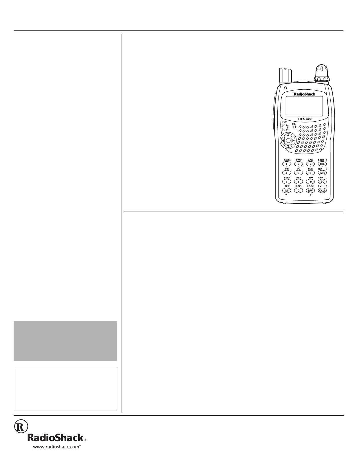
OWNER’S MANUAL — Please read before using this equipment.
Thank you for purchasing a RadioShack HTX-420 2-Meter/70 cm Dual Band FM Amateur
Transceiver. Your trans ceiv er is com pact a nd rugg ed, ma king it e asy to ca rry alm ost a nywhere .
The crystal controlled circuitry provides accurate and stable frequency selection, making it an
ideal choice for your amateur communications needs.
+0641&7%6+10"61"
#/#6'74"4#&+1
Amateur radio is a great hobby that has
enriched the lives of millions of people all
over the world. Your transce iver is the perfe ct
first radio for anyone entering the exciting
world of amateur radio, or as a great
additional transceiver for the experienced
amateur radio operator. Your transceiver
opens a door for you to th e world fr om almost
anywhere! All you need is an Amateur Radio
Operator's License (Technician Class or
higher) issued by the Federal
Communications Commission (FCC). If you
do not have a license, it is easy to get one,
and help from license d operators is av ailable.
Find out if there is a ham radio club in your
area. Most clubs welcome newc om ers and
are glad to help you get your license. Here
are a few tips to help you get started.
You can turn on your transceiver and scan
the entire band to hear what is going on;
however, do not attempt to transmit until
you get your license
a license, you are in violation of federal law
that can lead to severe penalties. Ham
operators take the FCC rules very seriously
. If you transmit wit hout
2002 RadioShack Corporation.
©
RadioShack and RadioShack.com are trademarks
All Rights Reserved.
used by RadioShack Corporation.
and want nothing to do with “bootleggers” –
their term for people who operate without a
license.
±±±±
If you do not hear anyone talking about a
local club as you li sten to local tran smissions ,
write to the American Radio Relay League
(ARRL) at the following address to find out
how to contact a local affiliate. The ARRL is
the national organization representing
amateur radio in the United States. The
league has more than 150,000 members.
Most are ham operators, or members in the
process of obtaining their license.
The American Radio Relay League
225 Main Street
Newington, CT 06111
http://www.arrl.org
Start studying for the license exams. Most
people can go from knowing absolutely
nothing about amateur radio to passing the
Technician written exam in less than a
month.
The exams test your knowledge of basic
radio regulations and elementary radio
theory. Many clubs hold license classes
which can be a fun and easy way to learn
Page 2

"9#40+0)"R"
ý
Using the Lithium-Ion Rechargeable
Battery Pack
When you remove the battery pack from the
transceiver, be sure to turn off the transceiver
before you remove the battery pack.
Using AA Batteries
• When you remove the battery holder to replace
the batteries, be sure to turn off the transceiver
before you remove the battery holder.
• Dispose of old batteries promptly and properly.
Do not burn or bury them.
Using the Lithium-Ion Rechargeable
Battery Pack
• The supplied adapter is designed only to
recharge the battery pack. Do not attempt to
transmit using the adapter to power the radio.
• Use a coin or other solid object to unlatch the
lock tab when you remove the battery pack.
Using AA Batteries
• Use only fresh batteries of the required size
and recommend type.
• Always remove old or weak batteries.
Batteries can leak chemicals that destroy
electronic circuits.
• Do not mix old and new batteries, different
types of batteries (standard or alkaline).
• If you do not plan to use the transceiver with
batteries for two weeks or more, remove the
batteries.
Using AC or DC Power
• You must use a Class 2 power
source that supplies 12V DC and
delivers at least 2A. Its center tip
must be set to positive and its plug
must fit the transceiver’s EXT jack. Using a
power supply that does not meet these
specifications could damage the transceiver
or the power supply.
• Always connect the power cable to the
transceiver before you connect it to the power
source. When you finish, disconnect the cable
from the power source before you disconnect
it from the transceiver.
Connecting the Antenna
Do not over-tighten the antenna.
Using the Lithium-Ion Rechargeable
Battery Pack
• The battery pack’s indicator does not change
to green if you use the transceiver while
charging the battery pack.
• Using a pencil eraser, clean the charging
contacts on lithium-ion battery pack.
Connecting the Antenna
You can connect an external antenna to the
transceiver using an SMA-to-BNC adapter. The
adapter and suitable antennas are available at
your local RadioShack store.
R
.
"%#76+10"
"016'"
±±±±
±±±±
.
!
"
about amateur radio. There are good books,
cassette tapes, computer programs, and
many other study aids available. Your local
RadioShack store sells FCC License
Preparation study guides for amateur radio
operator licenses. While you are no longer
required to learn M orse code for a Technician
Class license, we encourage you to learn it
so you can advance to higher levels of
operating privileges.
There is a small fee required for taking the
Technician exam. All license level tests are
administered by a three-member Volunteer
Examiner Team. Contact the ARRL for a
schedule of exam opportunities in your area.
The Technician Class license lets you use
the transceiver to communicate directly with
other operators, and use repe aters for distant
communication.
24'2#4#6+10
You can power your transceiver using
internal batteries, AC power or vehicle
battery power (using a RadioShack 270-031
power cable, not supplied, available at your
local RadioShack store or online at
www.RadioShack.com).
75+0)"+06'40#."$#66'4+'5
You can power the transceiver using the
supplied lithium-ion rechargeable battery
pack and its supplied adapter or four AA
alkaline batteries (not supplied), available at
RadioShack.
75+0)"6*'".+6*+7//+10"
4'%*#4)'#$.'"$#66'4;"2#%-
Before you use the lithium-ion rechargeable
battery pack, you must charge it. The battery
pack has a built-in charging circuit.
To charge the battery pack, connect the
supplied AC adapter to the battery pack ’s DC
12V jack. Then plug the adapter’s other end
into a standard AC outlet. If you have
installed the battery pack to the transceiver,
turn off the transceiver. The indicator on the
battery pack lights red while charging and
lights green when the charging finishes. A
fully discharged battery pack can take as
".
±±±±
long as 10 hours to fully recharge.
When the battery pack is fully charged,
unplug the adapter from the AC outlet, then
disconnect the adapter from the battery pack.
Install the battery pack by inserting its upper
edge first then press it down. Then lift and
press down the l oc k tab to s ecure the battery
pack.
When • appears, recharge the battery.
±±±±
RRRR
.#
75+0)"##"$#66'4+'5
You can power your transceiver using four
alkaline AA batteries (not suppl ied and
available at your lo cal RadioShack st ore) with
the supplied battery holder.
1. Insert four AA batteries into the supplied
battery holder according to the polarity
symbols (+ or –) marked on the holder.
2. Attach the battery holder onto the
transceiver and fasten the lock tab.
When • appears, replace the batteries.
RRRR
".
75+0)"#%"14"&%"219'4
To power the transce iver from an AC outlet or
your vehicle’s batt ery po wer, you need a 12V
regulated DC power supply that delivers at
least 2A (for AC) an d a RadioShack 270-031
power cable (not supplied, available at
RadioShack). Another type of cable mi ght not
.
work with your transceive r.
For AC power,
1.
voltage switch, set the switch to 12V.
2. Insert the power cable’s cord into the
transceiver’s
For AC power,
3.
the power cable to the power supply,
then plug the power suppl y’ s power co rd
into the power source.
For DC power,
power cable into the vehicle’s cigarette
lighter socket.
if the power supply has a
EXT
jack.
connect the other end of
plug the other end of the
%100'%6+0)"6*'"#06'00#
Place the threaded base socket of th e
supplied antenna over the antenn a connector
on top of the trans ceiver and turn the anten na
clockwise to tighten it. To remove the
antenna, turn it counterclockwise. .
#66#%*+0)"6*'"$'.6"%.+2
Use a Phillips screwdriver and the two
supplied screws to attach the supplied belt
clip to your transceiver. Do not overtighten
the screws.
#66#%*+0)"6*'"94+56"564#2
To attach the supplie d wrist strap to the top of
the belt clip, thread the strap's small loop
through the opening in the top of the clip.
Then insert the longer loop through the
smaller loop and pull on the strap until the
loop is tight.
%100'%6+0)"#"/+%412*10'1
52'#-'4
You can connect an external
communications headset (consisting of a
microphone and speaker) to the transceiver
so you can use it privately. Lift the hinged,
±±±±
2
Page 3
rubber dust cover from the
.
"%#76+10"
.
Use only microphone and speaker accessories
that do not share a common ground for the
speaker and the microphone. Doing otherwise
might damage the transceiver.
±±±±
"016'"
±±±±
"
Connecting a headset’s plug to the transceiver’s
SPK jack automatically disconnects the internal
speaker.
jacks on top of the transceiver. Then insert
the plug of an optional voice-activated
headset with microphone, or an optional
communication he adset, in to the jack s. .
You can also connect an optional mono
earphone to the
the transceiver's push-to-talk button (
transmit as usual. Your local RadioShack
store carries a wide selection of suitable
communications headsets, earphones, and
separate components.
SPK
SPK
jack. This lets you use
and
MIC
PTT
) to
±±±±
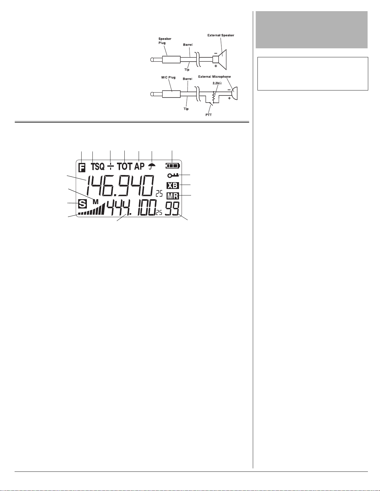
The following schematic diagram shows the
typical wiring for an ex ternal mic and
speaker.
#"37+%-".11-"#6"6*'"&+52.#;
3
4
1
2
56 7
16
15
14
13
1.y— appears when F (function) key is
pressed.
JJJJ
— appears when Tone Squelch
2.
(CTCSS) is enabled for transmitting. SQ
appears when Tone Squelch (CTCSS) is
enabled for receiving. TSQ appears
when Tone Squelch (CTCSS) is enable d
for transmitting and receiving.
3.+ — appears to indicate a positive
repeater offset. – indicates a n egative
offset.
JEJ
JEJ
— appears when a time for the time-
4.
JEJJEJ
out timer is selected.
7F
7F
— appears when Auto Power Off is
5.
7F7F
enabled.
— appears when the SAME alert is
6.
r
enabled. The icon flashes when the
transceiver is out of ra nge.
7.í — indicates the battery strength.
z
— indicates the keypad control is
8.
disabled to prevent accid ent al setting
changes.
12
8
9
10
11
11. 2-Digit Number below
memory location number.
12. Sub Frequency Display (appears on the
bottom of the display) — shows the
transmit frequency an d o the r s ett ing s. In
the compass mode, the display shows
direction indicator and angles in degree.
13. Signal Strength/Power Meter — shows
the relative signal strength or power
level.
— appears and flashes when power
14.
p
save is on.
CCCC
— indicates the output power is
15.
BBBB
middle.
low. When neither of these appears, the
output power is high.
16. Main Frequency Display (appears in the
middle of the display) — shows the
receive frequency.
7777
— appears when the trans ceiv er tunes
17.
to the air band. (Not shown on this
display.)
indicates the output power is
— indicates
o
9.
— appears when you use the cross
q
band feature.
10.
(Memory Channel Recall) —
o
appears when you recall a memory
channel.
3
Page 4

12'4#6+10
setting mode.
JN
JN JED;
JED;, ZJC<
JED;JED;
ZJC<, 7H;7
ZJC<ZJC<
JNJN
IGB
IGB, L><
L>< HFJ
IGBIGB
L><L><
7H;7
, and
7H;77H;7
HFJ, K><
K>< HFJ
HFJHFJ
K><K><
I7C;
I7C;
I7C;I7C;
HFJ, HN
HN JED;
HFJHFJ
HNHN
appear.
JED;
JED;JED;
,
"016'"
±±±±
Temporarily Opening Squelch
The current setting for Squelch, Repeater Offset
for the selected band, RX Tone, and TX Tone
can be displayed by pressing and holding M.
(see “Setting the CTCSS Tones” on Page 6) .
Selecting Frequencies and Receiving
Transmissions
• When you directly enter a frequency, the
transceiver accepts only six digits and it
automatically rounds down the last digit of
the frequency to 0 or 5. For example, if you
enter 440.244, your transceiver accepts it as
440.240. If you enter 440.248, the
transceiver accepts it as 440.245. If you set
the frequency step to 6.25 kHz, 7.5 kHz, or
12.5 kHz, you need to select frequencies
using CH, or
• If the transceiver picks up unwanted, weak
transmissions, set the squelch to a different
level (See “Setting the Squelch Level” on
Page 4).
It is illegal to transmit if you do not have at least a
Technician Class license issued by the FCC.
8or9
.
"%#76+10"
"
±±±±
.
.
/#07#."%108'06+105
Your transceiver's buttons perform multiple
functions. The abbreviation or symbol for a
function is printed on, above, or below each
button.
To activate certain transceiver features, you
must press F (function) and anot her butt on at
the same time. Those key combination
instructions are printed as first button name,
+, then the second button name. For
F+TOT
example,
you press
Button names are printed in small, bold,
capital letters such as
symbols, and numbers that appear on the
display are printed using a distinctive
typeface, such as
means hold down F while
TOT
.
CLR
or MR. Words,
'*,$/*&
'*,$/*&
'*,$/*&'*,$/*&
or
CH
CH
CHCH
.
6740+0)"1011(("6*'"
64#05%'+8'4
To turn on the transceiver, press
radio beeps once if the key tone feature is
enabled. Then the current battery voltage
briefly appears and the last used frequency
appears. To turn the transceiver off, press
PWR
again.
PWR
. The
5'66+0)"6*'"537'.%*".'8'.
Turn on the transceiv er then repeatedly p ress
6
or 7 until the current squ elc h s et ting (
&+
&+
to
&+&+
8
setting. A higher number reduces noise inbetween transmissio ns whil e a low er num ber
allows you to hear a weak transmission.
Press
setting and exit squelch setting.
IGB
IGB
) and
or 9 or rotate CH to change the squelch
appear. Repeatedly press
IGBIGB
PTT
or
(Push to Talk) to store the
&&
&&
&&&&
6'/214#4+.;"12'0+0)"
537'.%*
If you use the Tone Squelch (CT CSS) feature
(see “Setting the CTCSS Ton es” on Page 6),
you might not hear a transmission on the
current frequency. To temporarily open the
squelch so you can hear al l tran smissi ons on
M
the frequency, hold down
normal operation, release
. To resume
M
±±±±
.
75+0)"6*'"70+8'45#."6;2'"
-';5
Repeatedly press until the transceiver
displays a frequency from the desired band.
The band changes in the following orde r:
VHF, UHF, AIR, WX.
Repeatedly pressi ng
selection of squelc h, VHF repeater offset,
UHF repeater offset, receive tone squelch
(CTCSS), transmit tone squelch (CTCSS),
DTMF, SAME area code, and SAME on/off
6or7
allows
Press 8 or 9, or rotate CH to change the
value of the selected setting. Press
PTT
to store the setting and exit.
The detailed operation for squelch, VHF
repeater offset, UHF repeater offset, receive
tone squelch (CTCSS), t ransmit tone squelch
(CTCSS), DTMF, SAME area code, and
SAME on/off is described in the relevant
sections.
5'.'%6+0)"(4'37'0%+'5"* &+4'%6"
670+0)+"#0&"4'%'+8+0)"
64#05/+55+105
1. Repeatedly press to select the
desired receiving mode (VHF, UHF, Air,
Weather).
2. Select a frequency using one of the
following methods.
Using
CH: Rotate CH clockwise or
counterclockwise to select a frequency
(or channel for the weather band). The
frequency changes in increments you
set (see “Setting the Freq uency Step” on
Page 8) for each rotati on click. Hold
F
while rotating CH to change the
down
frequency by 1 MHz increments
regardless of the selected step
frequency.
Using
8 and 9: Repeatedly press (or
hold down)
frequency appears. Hold down
pressing
frequency by 1 MHz increments.
Using Direct Key Entry
keys to directly enter a frequency,
including the three numbers to the right
of the decimal. (You do not enter the
decimal point.)
VOL
3. Set
level.
8
or 9 until the desired
8
or 9 to change the
: Use the number
±±±±
to a comfortable listening
±±±±
64#05/+66+0)
There are two basic types of communication
possible with this transceiver: radio-direct-toradio (simplex) or radio-to-repeater-to radio
(duplex). Simplex uses the same frequency
to send and receive. Duplex uses one
frequency to trans mi t a nd ano ther to receive.
For more information about duplex, see
“Understanding Repeaters” on Page 5.
1. Select the desired transmit band VHF/
UHF and frequency using manual or
direct entry.
2. Hold the transcei ver a bout 3 inch es fro m
your mouth.
or
F
while
.
4
Page 5

3. Hold down
±±±±
"016'"
±±±±
"
Setting the Repeater Offset Frequency
This setting only affects the VFO mode. If you
saved a frequency offset in a memory location,
that setting is not affected.
Memory Operation
You cannot activate or deactivate the power
save, auto power-shut off, time-out timer,
frequency step, key tone on and off, and call
features in memory mode.
speak slowly and clearly into the
microphone.
PTT
(Push to Talk), then
2. Repeatedly press 8 or 9, or rotate CH
to change the offset to a new value
ranging from .000 to 8.000 MHz.
PTT
4. Release
transmitting.
when you finish
70&'456#0&+0)"
4'2'#6'45
A repeater is a radio that receive s a signal on
one frequency (the input frequency) and
retransmits that signal on a different
frequency (the output frequency). Repeater
antennas are typically located at the tops of
tall buildings or on antenna towers, so a
relatively low-power signal can reach the
repeater. The repeater retr ans mi ts the signal
at a higher powe r. This give s your trans ceiver
the ability to communicate over a much
greater range.
To use a repeater, you must know the
repeater's input and output frequencies.
Repeaters are usually identified by their
output frequency. Thus, a repeater that has
an output frequency of 146.94 is referred to
as the “146.94 repeater.” To determine the
input frequency, you must know the
frequency offset (typically 600 kHz for the 2meter band and 5 MHz for the 70-cm band)
and the offset direction (+ if you add the
offset (600 kHz) to the output, or – if you
subtract the offset (600 kH z) from the ou tput).
Whether the offset is positive or negative
depends on:
• which part of the band the repeater
operates on
• local convention
• proximity of repeaters using the same
two frequencies
To determine the offset and the direction,
obtain a copy of
Handbook
RadioShac k store or the ARRL). That
publication lists the locations of repeaters as
well as their fre que ncy and offset information.
A
+ above the displayed frequency indicates
a positive offset, while a – above the
frequency indicates a negative offset. If
neither +, nor – appears, the transceiver is
set for simplex operation.
5'66+0)"6*'"4'2'#6'4"1((5'6"
(4'37'0%;
The transceiver’s default repeater offset is
600 kHz for the VHF band and 5 MHz for the
UHF band. As the display shows all
frequencies in MHz, you see
VHF and
1. Repeatedly press 6 or 7 until
appears.
The ARRL Repeater
(available through your local
+$&&&
+$&&&
(MHz) for UHF.
+$&&&+$&&&
$,&&
$,&&
(MHz) for
$,&&$,&&
±±±±
L><
L>< HFJ
HFJ
L><L><
HFJHFJ
3. Press
4. Repeatedly press 8 or 9, or rotate CH
5. Press
7
to change the offset to a new value
ranging from .000 (no offset) to 8.000
MHz.
exit.
K><
K>< HFJ
until
or
HFJ
appears.
K><K><
HFJHFJ
PTT
to store the setting and
6740+0)"4'2'#6'4"12'4#6+10"
1011(("#0&"%*#0)+0)"6*'"
1((5'6"&+4'%6+10
To use the transceiver with a repeater, you
must set either a + or – repeater offset
direction. To turn on operation for use with a
repeater in the VFO mode, press
current offset indicator (+ or –) appears. To
turn off repeater operation, repeatedly press
F++/–
until neither + or – appears.
If you want to reverse the repeater input and
F+REV
output frequencies, press
.
/'/14;"12'4#6+10
Your transc eiver has 100 standard memory
locations that you can use to store
frequencies for quick access. You can store
frequencies used fo r the VHF, UHF , AIR, and
WX bands. When you store a frequency,
other settings associated with that frequency
(such as the repeater offset and CTCSS
tones) are stored as well.
5614+0)"#"64#05/+614'%'+8'"
(4'37'0%;
1. Select the frequency you want to store.
Once you sele ct a frequency, the other
values such as the repeater offset and
the CTCSS tones for that repeater are
also stored in the memory location. To
select other settings, see “Setting the
Repeater Offset Frequency” on Page 5,
“Setting the CTCSS Tones” on Page 6,
and “Using DTMF Code” on Page 7.
F+MW
2. Press
vacant memory location appears.
3. Repeatedly press
select the desired memory location.
4. Press
selected frequency and exit the me mory
mode. If a memory location already has
a frequency stored in it, the new
frequency is stored in its place.
4'%#..+0)"/'/14;".1%#6+105
To recall a save d memory locat ion, press MR.
appears and the last used memory
o
.
o
MW
or F+MW again to store the
±±±±
flashes and the lowest
8
or 9 or turn CH to
F++/–
. The
5
Page 6

location number appears beneath o. Then
CH
turn
different memory location. To return to VFO,
press
or press 8#or 9 to select a
.
2. To change the scan direction, press
9
or
or rotate CH.
3. To stop on a frequency or to stop
SC
scanning, press
or
PTT
.
8
"016'"
±±±±
Clearing a Single Memory
You cannot clear memory location number 1.
Skipping Memory Channels While
Scanning
You cannot skip memory channel &'
±±±±
"
&'.
&'&'
%*'%-+0)"/'/14;".1%#6+10"
5'66+0)5
To check all the settings stored in a memory
MR
location, press
9
or
) to select the desired memory location .
Then hold down
memory location appe ar in seque nce startin g
with the squelch setting value and ending
with the frequency.
, then rotate CH (or use 8
M
. The settings sto r ed in the
%.'#4+0)"#"5+0).'"/'/14;
Follow these steps to clear any single
memory location. (To clear all memory
locations, see “R es ett ing th e Tran sc eiv er” on
Page 11.)
MR
1. Press
location number appear.
2. Repeatedly press
CH
location.
3. Press
location is cleared.
. o and the last used me mory
8
or 9, or rotate
, to select the desired memory
F+CLR (6
). The selected memory
±±±±
75+0)"6*'"%#..+0)/(4'37'0%;"
/'/14;
The calling-frequency memory location lets
you quickly ju mp to a specific frequency. The
preset calling frequency is 146.520 MHz in
the VHF band and 446.000 MHz in the UHF
band. You can store a different frequency
into this memory, as well as other settings
associated with that frequency, such as the
repeater offset and CTCSS tone. You can
use this feature when the transceiver is in
VFO mode.
CALL
Press
frequency. The frequency (such as 146.520)
and
VFO mode.
To change the stored frequency, select a
new frequency, then press
to display the current calling
9999
appear. Press
CALL
again to return to
F+ CALL (CM
).
5%#00+0)"56#0&"/'/14;"
.1%#6+105
1. Press MR (so o appears), then press
SC
. The decimal point flashes while the
transceiver scans all but empty
locations.
2. To change the scanning direction, press
8
or 9 or rotate CH.
SC, PTT
3. To stop scanning, press
, or .
5-+22+0)"/'/14;"%*#00'.5"
9*+.'"5%#00+0)
While scanning memory channels, you can
skip channels you do not want to receive.
You cannot use this feature for normal
frequencies.
To skip a channel, select the channel in
memory mode, then press F+M (
SC
flashes. Pr ess
You can also skip a channel when the
transceiver stops while scanning by pressing
F+M (SKIP
scanning after you press
To clear a channel (turn off skip) skip
memory, press
to scan memory channels.
). The transceiver resumes
F+M (SKIP
SKIP
F+M (SKIP
).
). o
±±±±
).
%106+07175"610'"
%1&'&"537'.%*"
5;56'/"('#674'5"
*%6%55+
Your transceiver can transmit and receive a
low-level, selectable subaudible tone at the
same time as it receives (RX) or transmits
(TX) a regular signal. This special tone lets
you listen only to oth er radios s et to the sa me
tone frequency when y ou use the tra nsce iver
in simplex operation. The CTCSS feature
also lets you match your HTX-420 to the
subaudible tone frequency used by a local
repeater.
5%#00+0)"12'4#6+10
5%#00+0)"(14"#%6+8'"
(4'37'0%+'5
1. To search for activity on a frequency,
SC
press
up or down the band’s full frequency
range. The decimal point flashes as the
transceiver scans. The d isplayed
frequency stops on each active
frequency for 8 seconds.
6
. The transceiver begins to scan
5'66+0)"6*'"%6%55"610'5
To set the RX and TX tones for the
transceiver, follow these steps.
1. Repeatedly press
appears.
2. Press
3. Press
8
or 9, or rotate CH to select a
frequency or no frequency (
from the table Page7.
7
until
6
JN
JN JED;
JED;
JNJN
JED;JED;
or 7 until
9J9IIýe\\
9J9IIýe\\
9J9IIýe\\9J9IIýe\\
appears.
HNýJED;
HNýJED;
HNýJED;HNýJED;
)
Page 7

4. Press 8 or 9, or rotate CH to select a
±±±±
"016'"
±±±±
"
You can also hold down PTT and enter the first
character of the DTMF sequence. Then, release
PTT and continue to enter the balance of the
characters as long as you enter each character
within one second of the proceeding character
entry.
tone frequency from the list on Page 7.
5. Press
and exit.
PTT
or
to store the settings
75+0)"6*'"%6%55"610'5
You can use a tra nsm it to ne, a rec ei ve r tone,
or both. For example, if the sel ected rep eater
uses a receive only CTCSS tone, enable the
transmit tone but not the receive tone on the
HTX-420.
To enable only the
F+T.SQL (1
frequency. Press
).
To enable only the
F+T.SQL (1
displayed frequency. Press
setting.
) again.
To enable both the
receive
JIG
JIG
JIGJIG
Press
When you store a fr equency in on e of the 100
memory locations, all settings chosen for the
selected frequenc y are sto red as well. Before
you store a frequency (see “Storing a
Transmit/Receive Frequency” on Page5),
select the Subaudi ble Tone Freq uen ci es firs t.
(RX) tones
appears above the displayed frequency.
PTT
to store the setting.
transmit
JJJJ
appears above the displayed
PTT
receive
IG
IG
IGIG
transmit
, press F+
(TX) tone
to store the setting.
(RX) tone
appears above the
PTT
, press
, press
to store the
(TX) and
T.SQL (1
) again.
functions, which is handy if you are involved
with repeater administration. You can also
signal to another radio equipped to receive
DTMF codes.
6
1. Repeatedly press
appears. If no DTMF cod es are stored in
UýUýUýýUýUýU
memory,
2. Repeatedly press 8 or 9, or turn CH
to select the desired DTMF memory
location.
3. Enter up to 16 characters (
and
sounds a short beep for each entry, and
a long beep to indicate the sixteenth
character. If you try to enter more than
16 characters, the radi o sounds two
short beeps.
4. To confirm the DTMF characters, hold
down
to scroll it. If you make an entry error,
press F+
again.
To enter another DTMF sequence,
repeat Steps 2–4.
5. Press
in the selected memory location. The
transceiver returns to the VFO mode.
UýUýUýýUýUýU
UýUýUýýUýUýUUýUýUýýUýUýU
A
through F; E=∗, F=#). The radio
F
and rotate CH, or press 8 or 9
CLR (6
PTT
or
or 7 until
and
) and repeat Step 3
to store the sequence
ZJC<
ZJC<
ZJC<ZJC<
Zýb
Zýb
appear.
ZýbZýb
0
through 9,
5WDCWFKDNG"6QPG"(TGSWGPEKGU"**\+
67.0 118.8 183.5
69.4 123.0 186.2
71.9 127.3 189.9
74.4 131.8 192.8
77.0 136.5 196.6
79.7 141.3 199.5
82.5 146.2 203.5
85.4 151.4 206.5
88.5 156.7 210.7
91.5 159.8 218.1
94.8 162.2 225.7
97.4 165.5 229.1
100.0 167.9 233.6
103.5 171.3 241.8
107.2 173.8 250.3
110.9 177.3 254.1
114.8 179.9
75+0)"&6/("%1&'
DTMF (Dual-Tone Multi Frequency) tones
are those typically associated with the use of
your telephone. Your transceiver can
transmit up to 16 separate DTMF tones and
store a sequence of tones in up to 6 different
memory locations (d1 to d6). You can use
DTMF to transmit to a land-patch that is
connected to a telephone line. This also lets
you enable or disable certain repeat er
64#05/+66+0)"#"&6/("%1&'
You can transmit a DTMF code from stored
memory or by direct entry.
64#05/+66+0)"#"&6/("%1&'"
(41/"5614'&"/'/14;
1. Press F+
sequence appears.
2. Repeatedly press
CH
memory location. Then pre ss
3. Select a transmit frequency (see
“Selecting Frequencies (Direct Tuning)
and Receiving Transmissions” on
Page 4).
4. Press
DTMF code using the selected
frequency.
D.SEL
. The last stored DTMF
8#
or 9, or rotate
until you see the desired DTMF
PTT
to exit.
PTT
+ to transmit the selected
64#05/+66+0)"#"&6/("%1&'"
75+0)"&+4'%6"'064;
1. Hold down
2. Enter each character of the desired
DTMF code in order. The DTMF tone
sounds to confirm your entry.
PTT
(Push to Talk).
±±±±
75+0)"6*'"64#05%'+8'4"9+6*"
2#%-'6"4#&+1
You can connect your transceiver directly to
a packet radio terminal node controller
7
Page 8

"016'"
±±±±
• When the transceiver receives no signal
within an 8-second period,
indicating power save is active.
• When the transceiver receives a signal
during the 8-second period,
steady.
• The green signal indicator lights to indicate
that a signal has been received and that
power save is on stand-by.
• To use the transceiver for packet
communications, disable power save (see
“Using the Transceiver with Packet Radio”
on Page 7).
"
±±±±
begins flashing
p
remains
p
(TNC). See the following diagram for a
suggested connection. Refer to your TNC
instructions for details.
HTX-420
TNC
Computer
.1%-+0)"6*'"-';2#&
To lock the transc eiver’s keypad so you do
not accidentally change a setting, press
F+LOCK (DW
PTT, PWR, F
To unlock the keypad, press
again.
). This locks all buttons except
, and M.
F+LOCK (DW
)
.+)*6+0)"6*'"&+52.#;
When you press any k ey excep t
backlight turns on fo r about 5 seco nds. Press
M
to turn on the backlight.
PTT
or F, the
6740+0)"6*'"-';"610'"10"
#0&"1((
The transceiver is preset to sound a beep
each time you press a key. To turn off the
beep, press
To have the beep sound again, press
F+BEEP
F+BEEP
again.
8F
8F-E<<
.
8F8F
E<<
E<<E<<
briefly appears.
5'66+0)"6*'"(4'37'0%;"56'2
Follow these steps to change the frequency
increment used during scanning and
stepping to a frequency.
1. Press
2. Repeatedly press
3. Press
F+STEP
setting (in kHz) appear.
the desired new setting appears. You
can change the frequency step to 5 k Hz,
6.25 kHz, 7.5 kHz, 10 kHz, 12.5 kHz, 15
kHz, 20 kHz, 25 kHz, or 50 kHz.
IJ;Fý
IJ;Fý
.
and the current s tep
IJ;FýIJ;Fý
8
or 9 or CH until
PTT
or
to store your selection.
219'4"5#8'
Power save conserves battery power by
turning off power to the receiver part of the
transceiver and turning it on briefly every 8
seconds to check for a transmission.
To enable power save, press
appears.
To disable power save, press
disappears.
±±±±
F+PS (5
F+PS (5
). p
).
p
75+0)"#761"219'4"5*761((
Follow these steps to have the transceiver
automatically turn off after a preset period of
non-use.
1. Press
2. Repeatedly press either 8 or 9, or
3. Press
To turn off auto power-shutoff, press
again and select
F+APO (3
normally disabled.
CH
turn
to select a time period until
power shutoff. You can select
/&
/&
'(&
'(&
or
/&/&
'(&'(&
PTT
and exit.
). Auto Power Shutoff is
e<<
e<<
appears.
e<<e<<
minutes.
or to store your selection
e<<
e<<
.
e<<e<<
e<<
e<<, )&
)&, ,&
e<<e<<
)&)&
F+APO
,&
,&,&
.+/+6+0)"64#05/+6"&74#6+10"
*6+/'/176"6+/'4+
When you communicate using repeaters,
keep your transmis sions as brie f as possi ble .
Most repeaters have built-in timers that limit
single transmissions to 3 minutes or less.
You can set the transceiver to stop
transmitting if you exceed a set time limit with
a single transmission.
To set a value for the time-out timer, press
F+TOT (4
along with
or turn
interval (up to 20 minutes). When you select
a value for the time out feature,
Press
to the VFO mode.
). The default setting
JEJ
JEJ
. Repeatedly press 8 or 9,
JEJJEJ
CH
to select the desired time-out
PTT
or
to store the setting and exit
e<<
e<<
appears
e<<e<<
JEJ
JEJ
JEJJEJ
appears.
670+0)"6*'"9'#6*'4"4#&+1"
(4'37'0%+'5
The transceiver can receive seven NOAA
(National Oceanographic and Atmospheric
Administration) weather broadc ast
frequencies. To listen to the channel
broadcasting in your location, repeatedly
press
appears. Then rotate
8
channel from the following table.
to select the weather band.
CH
or repeatedly press
or 9 to select your local weather
%JCPPGN"0WODGT (TGSWGPE["*/*\+
9>#'
9>#'
9>#'9>#'
9>#(
9>#(
9>#(9>#(
9>#)
9>#)
9>#)9>#)
9>#*
9>#*
9>#*9>#*
9>#+
9>#+
9>#+9>#+
9>#,
9>#,
9>#,9>#,
9>#-
9>#-
9>#-9>#-
162.400
162.425
162.450
162.475
162.500
162.525
162.550
MN
MN
MNMN
75+0)"6*'"5#/'"#.'46
Traditional weather radios simply receive the
NOAA weather broadcast (usually within a
40-mile radius), then sound an alarm if any
emergency code was transmitted along with
the broadcast. People who live outside an
affected area are often alerted even when
their area is not affected, causing many of
,
8
Page 9

them to potentially ignore real weather
±±±±
"016'"
±±±±
"
Understanding SAME Codes
Most SAME codes begin with 0, which means
the code represents an entire county. The NWS
plans to eventually subdivide some large
counties. When that happens, each subdivision
will be assigned a digit from 1 through 9,
resulting in codes such as 148439, 248439, and
so on.
Turning on the SAME Alert
• When the SAME code is detected, the audio
is muted.
• If you do not program any SAME codes into
the transceiver’s memory, the transceiver
detects all SAME signals when the SAME
function is on.
Using the Electronic Compass
• The compass is not intended to be used as a
scientific instrument. The accuracy of the
compass is affected by environmental
factors in the area where the radio is being
used.
9E#;HH
9E#;HH9E#;HH
9E#;HH appears when the transceiver
does not detect compass data. If
9E#;HH
9E#;HH9E#;HH
9E#;HH
appears, repeat Steps 1–5 to re-calibrate the
compass.
• To use the electronic compass feature, you
need to hold the transceiver within 30
degrees of a horizontal position.
warnings that can save lives.
In 1994, NOAA began broadcasting SAME
(Specific Area Message Encoding) codes
along with their sta ndard w eath er broad casts
from local stations in yo ur ar ea. SAM E codes
identify the type of emergency and the
specific geographic area (such as a county)
affected by the emergency. Your transceiver
receives, interprets, and d is pla ys information
about the codes so you can determine if the
emergency might affect your area. Only
SAME-compatible radios (such as this
transceiver) are able to take advantage of
this new technology.
Each SAME code identifies a specific
geographic area (defined by the National
Weather Service [NWS]), so your transceiver
sounds an alert only when a weather
emergency is declared in that area. This
helps you more efficiently track the weather
conditions in and around your area.
The transceiver displays one of the following
codes when it receives an alert signal.
M7HD
M7HD
for Warning
M7HDM7HD
M7J9>
M7J9>
for Watches
M7J9>M7J9>
IJCJ
IJCJ
for Statement
IJCJIJCJ
J;IJ
J;IJ
for Test
J;IJJ;IJ
The weather alert operates only when the
transceiver is in weather mode.
±±±±
'06'4+0)";174"#4'#N5"5#/'"
1&'5
%
You can store up to nine SAME codes. Refer
to the SAME codes at
www.nws.noaa.gov/nwr/indexnw.htm
corresponding codes for any specific area
you wish to monitor for weather warnings or
watches.
1. Repeatedly press
appears. If no SAME cod es a re st ored i n
memory, _ _ _ _ _ _ and
http://
6
or 7 until
7'
7'
appear.
7'7'
. for the
7H;7
7H;7
7H;77H;7
70&'456#0&+0)"5#/'"%1&'5
For the purpose of broadcasting weather
information, the NWS divided the United
States into regions by state and county (or
parish, where applicable) then assigned a
six-digit SAME code to identify each county
or parish. For example, the code for Tarrant
County, Texas, is 048439.
The first digit in a SAME code identifies the
county subdivision, the next two digits identify
the state, and the l ast thre e di gi ts i dentify the
county or parish.
Your transceiver can receive all SAME alert
signals broadcast within about a 40-mile
radius. To receive SAME alerts and
broadcasts about weather occurring only in
particular counties within that area, you can
program up to nine SAME codes into the
transceiver’s memory (see “Entering Your
Area’s SAME Codes” on Page 9). For
example, this lets you avoid hearing an alert
that applies to an area within a 40-mi le radius
but not necessarily to your county or parish.
6740+0)"10"6*'"5#/'"#.'46
When your local weather station broadcasts
a weather alert sig nal, the trans ceiver sou nds
an alert tone and disp lays an alert code for 5
seconds, showing the level of alert being
broadcast. Follow thes e ste ps to turn on the
alert.
1. Repeatedly press
weather mode.
2. Repeatedly press
appears.
3. Press
4. Press or
±±±±
8
or 9 to select
PTT
to select the
6
or 7 until
ed
ed
. r appears.
eded
to store the setting.
I7C;
I7C;
I7C;I7C;
2. Repeatedly pres s 8 or 9 to select the
desired memory location (A1–A9).
3. Enter your area’s SAME code using the
number keys.
If you want to enter another SAME code,
repeat Steps 2 and 3.
PTT
or
4. Press
exit.
to store the code and
75+0)"6*'"'.'%6410+%"
%1/2#55
Your transceiver has an electronic compass
that can display two digits of direction such
as SE or NW and up to three digits of
directional angle such as 360°, 180°, 90°, or
45° in five degree steps.
You must calibrate the electronic compass
before using it.
1. Turn off the transceiver.
2. Place t he transceiver horizontally on a
flat surface that does not give off
electrical or magnetic interference.
COMP
or .
, and
and press
±±±±
DM
DM
. If you press any
DMDM
3. Hold down
4. Place your index fi nger on t he side of the
transceiver’s antenna and turn the
transceiver clockwise or
counterclockwise, twice, smoothly and
continuously. Take 8 to 9 seconds to
complete a circle.
5. Press
To use the electronic compass press
F+COMP (H/L
The display provides 8 primary directions;
D;
D;, ;;;;, I;
D;D;
key, the compass display di sappears.
PTT
) to see the magnetic direction.
I;, IIII, IM
IM, MMMM
I;I;
IMIM
PWR
.
DDDD
,
±±±±
9
Page 10

"016'"
±±±±
Cross Band Channel Operation
You cannot transmit and receive at the same
time.
Changing the Transmit Frequency
Range
The extended transmit frequency range feature
is only for MARS, CAP, and public service
users. Once you change the setting to the
extended ranges, be sure not to transmit on
those frequencies unless you are licensed to do
so.
±±±±
"
5'.'%6+0)"6*'"64#05/+6"219'4
You can select one of the three transmitting
CCCC
power levels: High (no display), Mid (
BBBB
appears), and Low (
level, repeatedly press
appears). To select the
H/L
.
%4155"$#0&"%*#00'."
12'4#6+10
You can select a transmit frequency in the
VHF band and a receive frequency in UHF
band or vise versa. Or, you can select a
transmit frequency and a receive frequency
in the same band.
1. Press F+
is duplicated at the sub frequency
display.
main frequency display.
2. Enter the transmit frequen cy on the main
frequency display.
3. Press
4. Enter the receive frequency on the main
F+REV (8
frequency display and sub frequency
display.
frequency display.
±±±±
XBO (SC
q
). The main frequency
appears to the right of the
) to exchange the main
4'%'+8+0)"6*'"#+4"$#0&
Repeatedly press until
the airband at the top of the display. Press
8
or 9, or rotate CH to tune to the
frequency you want to hear. The air band
receiving range is 108 to 136.9875 MHz.
7777
appears to sele ct
%*#0)+0)"6*'"64#05/+6"
(4'37'0%;"4#0)'
You can change the standard transmit
frequency ranges to extended ranges.
Standard Transmit Frequency Ranges:
2 m: 144–148 MHz
70 cm: 438–450 MHz
Extended Transmit Frequency Range:
2 m: 142.000–149.880 MHz
70 cm: 420.000–470.000 MHz
To extend the range, turn off the transceiver.
SC+9
Then while holding down
To return to the standard range, repeat the
above steps.
, press
±±±±
PWR
.
5. Press PTT to transmit using cross band.
To exit the cross band channel operation,
press
F+XBO (SC
).
&7#."9#6%*
You can set the transceiver to check a
specified channel every 2.5 seconds while
receiving any othe r channel. If the tr ansceiver
finds a signal on the specified channel, it
automatically switches to it.
1. Select a frequency you do not want to
miss while you receive another
frequency.
DW
2. Press
the selected frequency on the sub
frequency display.
3. Select a frequency you want to receive
on the main frequency display.
The transceiver s cans the cha nnel on the s ub
frequency display every 2.5 seconds.
If you press
the frequency on the sub frequency display
and the dual watc h is c anceled. If you w ant to
transmit the frequency on the main frequenc y
display, press F+
frequencies.
If you hold down
the frequency on the sub frequency display
until you release
. The transceiver duplicates
PTT
, the transceiver transmits
REV
to exchange the
M, the transceiver scans for
M
.
(%%"+0(14/#6+10
This device complies with Part 15 of the
Rules
. Operation is subject to the following
two conditions: (1) This device may not
cause harmful interference, and (2) this
device must accept any interference
received, including interference that may
cause undesired operation.
FCC
%#4'
Keep the transceiver dry; if it gets wet, wipe it
dry immediately. Use and store the
transceiver only in normal temperature
environments. Handle the transceiver
carefully; do not d rop it. Keep the tra nsc ei ver
away from dust and dirt, and wipe it with a
damp cloth occasionally to keep it looking
new.
'44"&+52.#;
If you use your transceiver in an area (such
as a vehicle) that has many metal surfaces,
the transmitted signal can reflect back into
the radio and cause the P LL circ uit to u nlock .
;HH
;HH
If this happens,
inherent problem with this type of transc eive r.
To avoid this problem, you can try reducing
output power, use an external antenna, or
relocate the tra nsceiver when
;HH
;HH
appears even when you are using an
;HH;HH
external antenna located away from the
transceiver, service might be required.
appears. This is an
;HH;HH
;HH
;HH
;HH;HH
appears. If
10
Page 11

5'48+%'"#0&"4'2#+4
.
"%#76+10"
.
This procedure clears all the information you
have programmed into the transceiver. Before
you reset the transceiver, try turning it off then on
again to see if it begins working properly.
±±±±
"016'"
±±±±
"
The software protocol and construction for a PC
interface cable is available in the 19-1108
Service Manual. You can order a service
manual through your local RadioShack store.
If your transceiver is not performing as it
should, take it to your loca l RadioSh ack store
for assistance. Modifying or tampering with
the transceiver’s internal components can
cause a malfunction and might invalidate its
warranty and void your FCC authorization to
operate it.
4'5'66+0)"6*'"64#05%'+8'4
If the transceiver’s display locks up or the
transceiver does not work properly after you
.
turn it on, you might need to reset it.
To reset the transceiver, turn it off then hold
F+6
down
and turn it on again. Al l th e di sp lay
indicators appear to co nfirm the reset
operation. Release F+6.
52'%+(+%#6+105
GENERAL
Frequency:
2-Meter....................................................................................... TX: 144–148 MHz, RX: 137–174 MHz
70-cm......................................................................................... TX: 438–450 MHz, RX: 420–512 MHz
Air Band................................................................... .... .... .... ......... .... .... .. ..........108.000-136.9875 MHz
Weather Band ................................................................................................................................ CH1–CH7
Frequency Generation ........................................................................... .. .... .. .... ....... .... .. .... .. PLL Synthesizer
Frequency Stability .......................................................................................................................... ± 10 ppm
Operating Temperature ..................................................................................... 14° to 140° F (–10° to 60° C)
Operating Voltage ................................................................................................................ DC 5 V to 13.8 V
Modulation ............................................................................................................................................... F3E
Impedance .......................................................................................................................................... 50 ohm
1
Dimension (HWD) ................................................................................. 4
Weight (w/rechargeable battery)........................................................................................... . 11.46 oz (325g)
RECEIVER
Circuit Type............................................................................................. Dual Conversion, Superheterodyne
IF Frequency:
1st IF.......................................................................................................................................... 45 MHz
2nd IF............................................................................... .. .. ..... .... .. .. .. .. .. .. ....... .. .. .. .. ................. 450 kHz
Sensitivity................................................................................................................... 0.2
Distortion.............................................................................................................................................5% Max
S/N Ratio..................................... ......................... ................................................... ....................... 34 dB Min.
Audio Output @ 10% THD.................................................................................................. 300 mW at 8 ohm
TRANSMITTER
Power Output ................................................................................................. 3 W, DC 7.2 V 4 W, DC 13.8 V
Distortion (nominal)..................................................................................................................... .. ............. 3%
Deviation .................................................................................................................................... ± 5 kHz Max.
S/N Ratio..................................... ......................... ................................................... ............................... 32 dB
Current Drain ..................................................... ....................... 1200 mA, DC 7.2 V 1500 mA, DC 13.8 V
/2 × 22/5 × 11/5 (122 × 61 × 31 mm)
V For 12dB Sinad
µ
±±±±
Specifications are typical; individual units might vary. Specifications are subject to change and improvement
without notice.
Limited One-Year Warranty
This product is warranted by RadioShack against manufactu ring defec ts in material and workm anship under norm al use for one (1) year from the date of purchase from Radio Shack company-owned stores and authorized RadioShack franchisees and dealers. EXCEPT A S PROVIDED HEREIN, RadioShack MAKES NO EXPRESS WARRANTIES AND ANY IMPLIED WARRANTIES, INCLUDING THOSE OF MERCHANTABILITY AND FITNESS FOR A PARTICULAR PURPOSE, ARE LIMITED IN DURATION TO THE DURATION OF THE WRITTEN LIMITED WARRANTIES CONTAINED HEREIN. EXCEPT AS PROVIDED
HEREIN, RadioShack SHALL HAVE NO LIABILITY OR RESPONSIBILITY TO CUSTOMER OR ANY OTHER PERSON OR E NTITY WITH RESPECT TO ANY L IABILITY, LOSS OR DAMAGE CAUSED DIRECTLY OR INDIRECTLY BY USE OR P ERFOR MANCE OF THE PRODUCT OR ARISING OUT OF ANY BR EACH OF TH IS WARRANTY, INCLUDING, BUT NOT LIMITED TO, ANY DAMAGES RESULTING
FROM INCONVENIENCE, LOSS OF TIME, DATA, PROPERTY, REVENUE, OR PROFIT OR ANY INDIRECT, SPECIAL, INCIDENTAL, OR CONSEQUENTIAL DAMAGES, EVEN IF RadioShack HAS BEEN ADVISED OF THE POSSIBILITY OF SUCH DAMAGES.
Some states do not allow limitations on how long an implied warranty lasts or the exclusion or limitation of incidental or consequential damages, so the above limitations or exclusions may not apply to you.
In the event of a product defect during the warranty period, take the product and the RadioShack sales receipt as proof of purchase date to any RadioShack store. RadioShack will, at its option, unless otherwise
provided by law: (a) correct the defect by product repair without charge for parts and labor; (b) replace the product with one of the same or similar design; or (c) refund the purchase price. All replaced parts and
products, and products on which a refund is made , become the property of RadioShack. New or reconditioned parts and products may be used in the performance of warranty service. Repaired or replaced parts
and products are warranted for the remainder of the original warranty period. You will be charged for repair or replacement of the product made after the expiration of the warranty period.
This warranty does not cover: (a) damage or failure caused by or attributable to acts of God, abuse, accident, misuse, improper or abnormal usage, failure to follow instructions, improper installation or maintenance, alteration, lightning or other incidence of excess voltage or current; (b) any repairs other than those provided by a RadioShack Authorized Service Facility; (c) consumables such as fuses or batteries; (d)
cosmetic damage; (e) transportation, shipping or insurance costs; or (f) costs of product removal, installation, set-up service adjustment or reinstallation.
This warranty gives you specific legal rights, and you may also have other rights which vary from state to state.
RadioShack Corporation
Fort Worth, Texas 76102
RadioShack Customer Relations, 200 Taylor Street, 6th Floor, Fort Worth, TX 76102
12/99
19-1108
04A02
Printed in China
 Loading...