

%CNNGT"+&"2JQPG
YKVJ"5RGCMGTRJQPG
43-946
A
%106'065
FCC Statemen t ................. ............. 2
Lightning ..................................... 3
Important Information ..................... 3
Preparation .................................... 4
Installing Batteries ...................... 4
Mounting the Phone ................... 4
On a Desk .......................... ... .. 5
On a Wall or Wall Plate........... 5
Using the Data Jack ................... 6
Connecting the Handset ............. 7
Setting the Dialing Mode ............ 7
Setting the Ringer’s Volume ....... 7
Setting the Date and Time .......... 7
Setting the Display Language ..... 8
Setting the Area Codes .............. 8
Adjusting the Display Contrast ... 8
Operation .................... ................... 8
Switching Between the Handset
and the Speakerphone ............... 9
Setting the Hand se t Volume ....... 9
Setting the Speakerphone
Volume ............... ......................... 9
Using Redial ............................... 9
Using Call Wait ........................... 9
Using Hold ................................ 10
Using Tone Services on a Pulse
Line ........................................... 10
Memory Dialing ......................... 10
Storing Numbers from Caller ID
Records................................. 10
Entering a Pause in a Memory
Number ................................. 11
Dialing a Memory Number.... 11
Chain-Dialing......................... 11
Testing Stored Emergency
Numbers................................ 11
Using an Optional Headset ........ 11
Caller ID Operation ...................... 12
Reviewing Caller ID Records .... 12
Caller ID Messages .................. 13
Using Callback .......................... 13
Deleting Caller ID Records ....... 14
Troubleshooting ........................... 14
Care ............................................. 15
Service and Repair ...................... 15
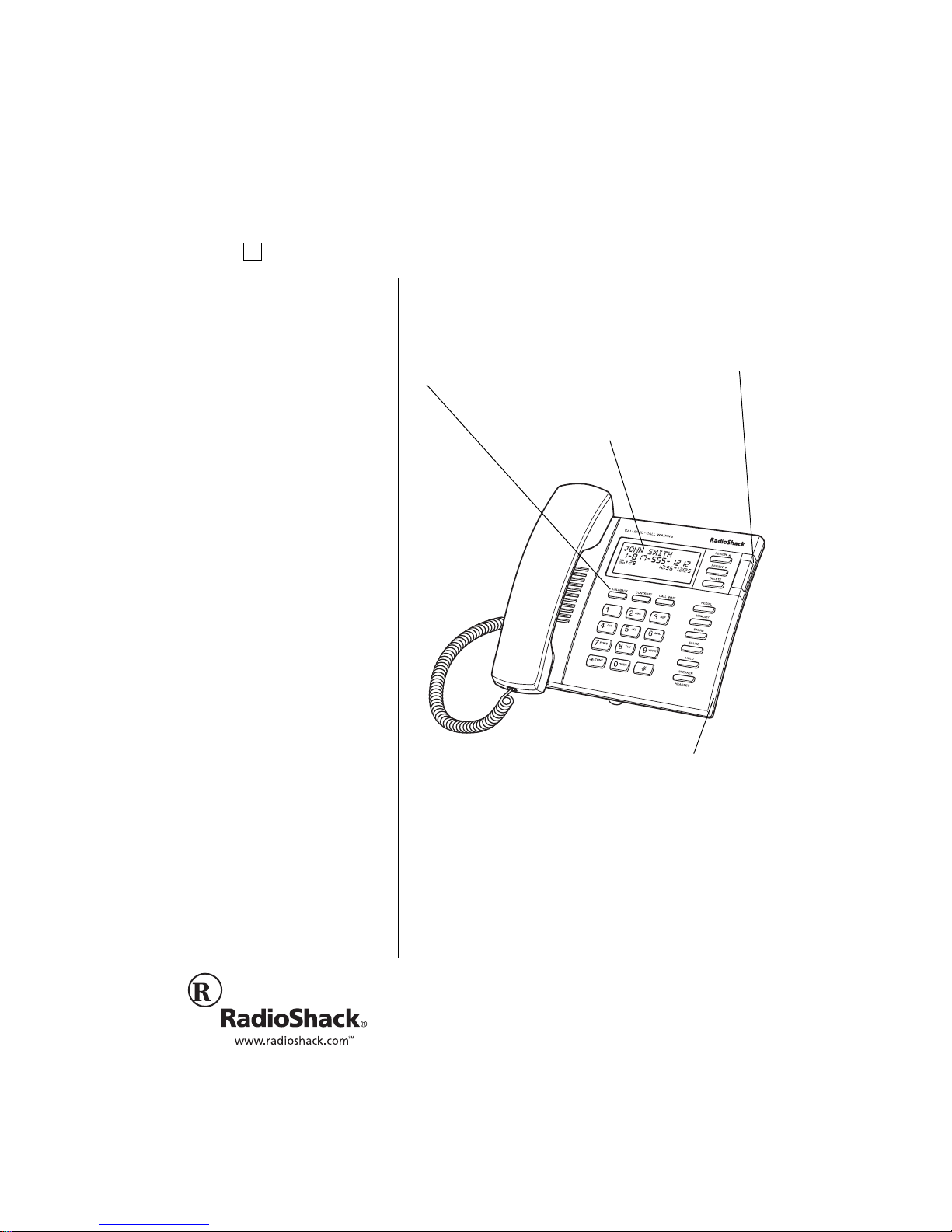
OWNER’S MANUAL — Please read before using this equipment.
Callback — lets you
dial the phone number
in a Caller ID record
with the touch of a
button (see “Using
Data Jack and Multiple
Extension Capacity — let you
connect an additional phone,
CID, or answering machine to
the phone on the same line.
Callback” on Page 13).
64 Memory Caller ID with New Call
Counter — stores up to 64 Caller ID records,
and shows the number of new calls received.
Call Waiting
Caller ID —
displays
information
about an
incoming call
while you are
on the phone.
Message Waiting — lets you
know that you have received
a voice mail message (if you
subscribe to a message
service from your local phone
company).
Headset Jack — lets you connect
an optional headset for hands-free
convenience while you use the
phone (see “Using an Optional
Headset” on Page 11).
Your RadioShack Caller ID Phone with Speakerphone is a
telephone that also shows the caller's telephone number
(and name, if availabl e in you r area) as well as th e date a nd
time of each call, as provided by your local telephone
company to Caller ID service subscribers.
2002 RadioShack Corporation.
©
RadioShack and RadioShack.com are trademarks
All Rights Reserved.
used by RadioShack Corporation.
"+/2146#06"
#
If an icon appears at the end of a
FCC Statement
paragraph, go to the box on that
page with the corresponding icon
for pertinent information.
— Warning # — Important
Rý
.... — Caution
±
— Note
°°°°
— Hint
#
(%%"56#6'/'06
This phone is Hearing Aid compatible.
Your telephone complies with Part 68 of
FCC Rules
. You
must, upon request, provide the FCC registration number
and the REN to you r telephon e compa ny. Both n umbers ar e
on the bottom of the telephone.
must not
You
connect your telephone to:
• coin-operated systems
• party-line systems
• most electronic key telephone systems
To reduce the risk of fire or shoc k
WARNING:
hazard, do not expose this product to rain or
moisture.
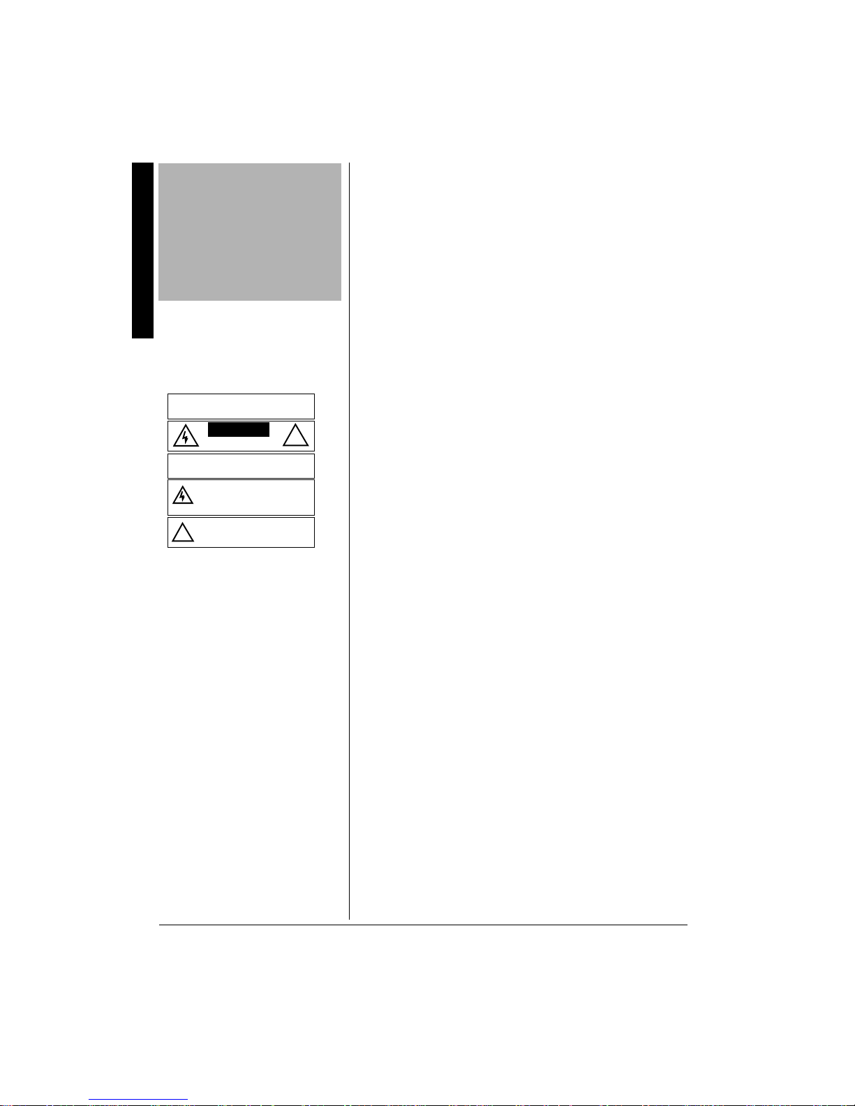
..
CAUTION
RISK OF ELECTRIC SHOCK
TO REDUCE THE RISK OF ELECTRIC
CAUTION:
SHOCK, DO NOT REMOVE COVER OR BACK. NO
USER-SERVICEABLE PARTS INSIDE. REFER
SERVICING TO QUALIFIED PERSONNEL.
The lightning symbol is intended to alert you to
the presence of uninsulated dangerous volta ge
within this product’s enclos ure th at might be of
sufficient magnitude to constitute a risk of
electric shock. Do not open the product’s case.
The exclamation symbol is intended to inf orm
you that important operating and maintenance
instructions are included in the literature
!
accompanying this product.
..
DO NOT OPEN
We have designed your telephone to conform to federal
regulations, and you can connect it to mo st tele phone lines.
However, each telephone (and each device, such as a
!
telephone or answering machine) that you connect to the
telephone line draws power from the telephone line. We
refer to this power draw as the device's ringer equivalence
number, or REN on the bottom of your telephone.
If you use more than one phone or other device on the line,
add up all of the RENs . If the tot al is more than fiv e (three i n
rural areas), your telephones might not ring. If ringer
operation is impaired, remove a device from the line.
Your phone is ETL listed to UL standards and meets all
applicable FCC requirements.
The phone also co mp lies with the limits for a Clas s B device
as specified in Part 15 of
FCC Rules
. These limits provide
reasonable protectio n against radi o and TV interfe renc e in a
residential area. However, your telephone might cause TV
or radio interference even when it is operating properly. To
eliminate interference, you can try one or more of the
following corrective measures.
• Reorient or relocate the TV's receiving antenna
• Increase the distance between the telephone and the
radio and TV.
2
Consult your local RadioShack store if the problem still
exists.
In the unlikely event that your phone causes problems on
the phone line, the phone company can temporarily
discontinue your service. If this happens, the phone
company attempts to notify you in advance. If advance

notice is not practical, the phone company notifies you as
soon as possible and advises you of your right to file a
complaint with the FCC.
Also, the phone company can make changes to its lines,
equipment, operations, or procedures that could affect the
operation of this telepho ne. The telephone company notifies
you of these changes in advance, so you can take the
necessary steps to prevent interruption of your telephone
service.
.+)*60+0)
Your phone has bui lt-i n pr otec ti on c irc ui ts to re duc e t he risk
of damage from surges in telephone line and power line
current. These protection circuits meet or exceed FCC
requirements. However, lightning striking the telephone or
power lines can damage your phone.
Lightning damage is not common. Nevertheless, if you live
in an area that has severe electrical storms, we suggest that
you unplug your phone during storms to reduce the
possibility of damage.
+/2146#06"+0(14/#6+10
To use the phone’s C al ler I D and Call Waiting features, you
must be in an area where Caller ID and Call Waiting
services are available and you must subscribe to the
services.
Important Information
Where Caller ID is offered, one or more of the following
options are generally available:
• caller's number only
• caller's name only
• caller's name and number
Your phone displays the caller's name only if that option is
available in your area.
The actual number of Caller ID records your phone will store
depends on the amount of Caller ID information sent by the
phone company.
3
"016'"±"
±
Installing Batteries
The phone retains all Caller ID
information when power is
interrupted. When replacing the
batteries, however, install the new
ones within 2 minutes of removing
the old ones, or the phone’s date
and time will be lost.
Mounting the Phone
• Your telephone connects
directly to a modular phone line
jack. If your phone line jack is
not a modular jack, you can
update the wiring yourself, using
jacks and adapters available
from your local RadioShack
store. Or, you can let the
telephone company update the
wiring for you.
• The USOC number of the jack
to be installed is RJ11C, or
RJ11W for a wall plate jack.
24'2#4#6+10
+056#..+0)"$#66'4+'5
Your phone requires four AAA batteries (not supplied) to
store and display Caller ID records. For the best
performance, we recom mend alka line batteri es, avail able at
your local Radi oShack store.
1. Use a Phillips scre wdriver to re move the scr ew from the
battery compartment cover.
2. Press in the tab on the top of the battery compartment
cover and lif t off the cover.
3. Place the batteries in the compartment as indicated by
the polarity symbols (+ and –) marked inside.
4. Replace the cover and secure it with the screw.
Once you install the batteries,
The telephone company sends the correct time with each
incoming call, so the c orrect date and time are au tomatica lly
set when the phone receives its first call.
When × flashes or the display dims, replace the batteries.
±
ý'(0&&7Cý'%&'
ý'(0&&7Cý'%&'
ý'(0&&7Cý'%&'ý'(0&&7Cý'%&'
....
appears.
Preparation
.
"%#76+10"
• Use only fresh batteries of the
required size and
recommended type.
• Do not mix old and new
batteries, different types of
batteries (standard, alkaline, or
rechargeable), or rechargeable
batteries of different capacities.)
• Always remove old or weak
batteries. Batteries can leak
chemicals that can destroy
electronic parts.
• Dispose of old batteries
promptly and properly. Do not
burn or bury them.
4
.
/1706+0)"6*'"2*10'
You can place the phone on a desk or table, mount it on a
standard wall plate, or mount it directly on a wall.
Select a location that is:
• near an AC outlet
• near a modular phone line jack
• out of the way of normal activities
±
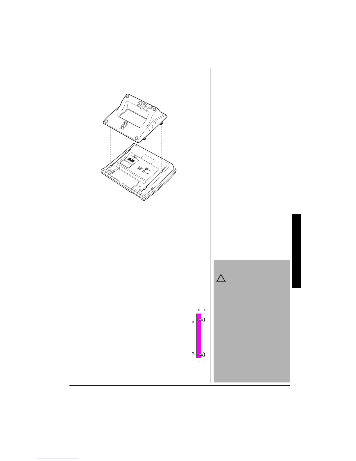
10"#"&'5-
1. Insert the mounting bra cket’s four tabs into t he s lo ts o n
the bottom of the base (as shown) then slide up and
snap the mounting bracket into place.
2. Plug one end of the supplie d long modul ar cord into the
LINE
jack on the bottom of the base. Then route the
long modular cord through the strain left slot on the
mounting bracket.
3. Insert the supplied AC adapter’s barrel plug into
200mA
jack on the bottom of the base. Then route the
DC 9V
adapter’s cord through the right slot on the mounting
bracket.
....
4. Plug the modular co rd’s other end i nto a modular p hone
line jack, and plug the adapter into a standard AC
outlet.
10"#"9#.."14"9#.."2.#6'
To mount the phone directly on a wall, you
need two screws (not supp lie d) w ith hea ds th at
fit the keyhole slots on the bottom of the pho ne.
Drill two holes 3
Then thread a screw into each hole, letting the
heads extend about 3/16 inch (5 mm) from the
wall.
1. Place the flat end of the mounting bracket
face up and insert the bracket’s four tabs
into the matching slots on the bottom of the
base. Then slide up and snap the bracket into place.
15
/16 inches (100 mm) apart.
315/
16
.
"%#76+10"
You must use a Class 2
!
power source that supplies
9V DC and delivers at least
200 mA. Its center tip must be set
to negative and its plug must fit the
3
phones’s DC 9V 200mA jack. The
16
/
supplied adapter meets these
specifications. Using an adapter
that does not meet these
specifications could damage the
phone or the adapter.
• Always connect the AC adapter
to the phone before you
connect it to AC power. When
you finish, disconnect the
adapter from AC power before
you disconnect it from the
phone.
.
Preparation
5

Strain Reli e f Sl ot s
Key Hole Slots
2. Plug the supplied long modular cord (or the short cord
for a wall plate) into the
LINE
jack on the bottom of the
phone.
3. Insert the supplied AC ada pte r 's ba rrel pl ug i nto the
9V 200mA
jack.
DC
4. If you are mounting the phone on a wall, route the
adapter and modu lar co rd th rou gh the strain relief sl ots
as shown. Align the phone’s keyhole slots with the
screws and slide the ph one downward to secu re it, then
plug the modular cord into a modular phone line jack.
Preparation
If you are mounting the pho ne on a wall plate , route th e
adapter cord as shown. Plug the modular cord into the
wall plate jack, t hen align the ph one's keyh ole slots wi th
the wall plate studs and slide the phone downward to
secure it.
5. Plug the AC adapter into a standard AC outlet.
75+0)"6*'"#",#%-
To connect
other phone
or an
answering
machine to
the phone on
the same
phone line,
plug one end
of the
modular cord
into the
DAT A
DATA Jack
6

jack at the right side of the phone, then plug the other end
into the other phone’s or answering machine’s jack.
%100'%6+0)"6*'"*#0&5'6
Plug one end of the supplied coiled cord into the modular
jack on the left side of the base and the other end into the
modular jack on t he han dset. The n place the handset on the
±
base.
5'66+0)"6*'"&+#.+0)"/1&'
TONE/PULSE
Set
not sure which type you have, do this simple test.
TONE/PULSE
1. Set
2. Lift the handset or press
tone.
3. Press any number other than 0.
If the dial tone stops, you have touch-tone service.
Leave
continues, you have pulse service. Set
PULSE
4. If you have pulse service, set
Otherwise, leave it set to
for the type of se rvi ce y ou hav e. If y ou are
on the bottom of base to
SPEAKER
and listen for a dial
±
TONE/PULSE
set to
TONE
. If the dial tone
TONE/PULSE
.
TONE/PULSE
TONE
.
TONE
PULSE
to
.
to
.
"016'"±"
±
Connecting the Handset
Your local RadioShack store sells a
variety of longer coiled handset
cords, which are especially useful
when you mount the phone on the
wall.
Setting the Dialing Mode
If your phone system requires that
you dial an access code (9, for
example) before you dial an
outside number, do not press that
number.
Setting the Date and Time
If you make a mistake, wait about 2
minutes. The phone beeps and
exits setup. To continue setting the
time, start again at Step 1.
5'66+0)"6*'"4+0)'4N5"81.7/'
RINGER OFF/LO/HI
Set
HI
volume, or
for a louder ring.
If you do not want the ringer to sound, set
HI
OFF
to
. With the ringer off, you can still make calls (and
on the base to LO for normal ringer
RINGER OFF/LO/
answer calls) if y ou hear another phone on the same phone
line ring or if you see the Caller ID information appear.
5'66+0)"6*'"'"#0&"6+/'
Your phone company sends the date and time with each
incoming call if you subscribe to Caller ID service. Or, follow
these steps to set the date and time.
1. Press
2. Press
STORE
REVIEW
FHE=H7CýCE:;
FHE=H7CýCE:;
so
FHE=H7CýCE:;FHE=H7CýCE:;
8888
-:-- -/- -
.
3. Enter the desired date using the number keys. For
01 04
example, press
for January 4.
and the hour cursor flashes.
±
appears.
I;Jý:7J;
I;Jý:7J;
and
I;Jý:7J;I;Jý:7J;
I;JýJ?C;
I;JýJ?C;
I;JýJ?C;I;JýJ?C;
appear.
appears
Preparation
7

4. Enter the current time.
"016'"±"
±
Setting the Display
Language
If you do not press any key within 2
minutes, the phone automatically
selects English.
Setting the Area Code
If you make a mistake while setting
the area code, press and release
the switch hook and start over from
Step 1.
TONE
/
5. Press
*
appears for AM time, and
phone beeps and the set time display returns.
to select AM or # to select PM.
FC
FC
appears for PM time. The
FCFC
7C
7C
7C7C
5'66+0)"6*'"&+52.#;".#0)7#)'
The phone is pres et to s how C aller ID mess ages i n Engli sh.
Follow these steps to change the language to French or
Spanish.
1. Press
2. Press
3. Press:
The phone beeps once, then returns to the current time
display.
STORE
REVIEW
appears.
1
to select English
•
2
to select Spanish
•
3
to select French
•
FHE=H7CýCE:;
FHE=H7CýCE:;
.
FHE=H7CýCE:;FHE=H7CýCE:;
9999
±ý
I;JýB7D=K7=;
I;JýB7D=K7=;
.
I;JýB7D=K7=;I;JýB7D=K7=;
appears.
then
'3;Dý(3IFý)3<H
'3;Dý(3IFý)3<H
'3;Dý(3IFý)3<H'3;Dý(3IFý)3<H
5'66+0)"6*'"#4'#"%1&'5
Enter your local area cod e before yo u receive cal ls to insu re
that your phone records the correct Caller ID and dial back
information.
Operation
1. Press
2. Press
3. Enter the desired area code.
4. After you set the area code’s last digit, press
STORE
CALLBACK
&&&&
flashes.
first
CALLBACK
FHE=H7CýCE:;ý
FHE=H7CýCE:;ý
.
FHE=H7CýCE:;ýFHE=H7CýCE:;ý
I;Jý7H;7ý9E:;
I;Jý7H;7ý9E:;
.
I;Jý7H;7ý9E:;I;Jý7H;7ý9E:;
. The phone beeps once.
appears.
and
±
&&&
&&&
appear. The
&&&&&&
#&,756+0)"6*'"&+52.#;"%1064#56
Repeatedly press
The phone beeps once when it reaches the darkest or the
lightest contrast.
CONTRAST
to adjust the display contrast.
12'4#6+10
To make a call with the han dset, p ick u p the ha ndset. When
you hear the dial tone, dial the phone number (you see the
8

number as you dial). Then (after about 15 seconds)
and the elapsed time for your call appear.
J?C;H
J?C;H
J?C;HJ?C;H
To make a call using the speakerphone, press
HEADSET
. SPEAKER/HEADSET lights. Dial the phone
SPEAKER/
number (you see the numbe r as y ou dia l). Then (after a bout
J?C;H
15 seconds)
J?C;H
and the elapsed time of yo ur call appear.
J?C;HJ?C;H
To answer an incoming call, pick up the handset or press
SPEAKER/HEADSET
. The elapsed time of the call appears.
To end a call, place the handset back on the base or press
SPEAKER/HEADSET
.
59+6%*+0)"$'69''0"6*'"*#0&5'6"#0&"
6*'"52'#-'42*10'
To switch from the handset to the speakerphone during a
call, press
SPEAKER/HEADSET
lights. Then place the handset on the base.
. SPEAKER/HEADSET
±
To switch from the speakerp hon e to th e hand set, ju st lif t th e
handset and resume your conversation. The speakerphone
and SPEAKER/HEADSET indicator automatically turns off.
5'66+0)"6*'"*#0&5'6"81.7/'
You can change the handset’s volume during a call by
HANDSET VOL. NORM/HI
sliding
to the desired listening
level.
5'66+0)"6*'"52'#-'42*10'"81.7/'
You can adjust the speakerphone’s volume during a
speakerphone call by sliding
SPEAKER VOL.
75+0)"4'&+#.
The redial memory holds up to 32 digits, so it can store
long-distance as well as local numbers.
±
To redial the last number you dialed, lift the handset or
SPEAKER/HEADSET
press
phone number and
:?7B?D=ý°
:?7B?D=ý°
:?7B?D=ý°:?7B?D=ý°
then press
appear.
REDIAL
. The dialed
75+0)"%#.."9#+6
CALL WAIT
the switchhook for special services, such as Call Waiting.
(flash) is the electronic equivalent of pressing
±
"016'"±"
±
Switching Between the
Handset and the
Speakerphone
• The speakerphone does not
operate without AC power.
During a power failure, use the
handset instead.
• You cannot use the
speakerphone with a headset
connected to the phone (see
“Using an Optional Headset” on
Page 11).
Using Redial
The redial memory does not store
a flash entry, only the digits you
press after CALL WAIT (see
“Using Call Wait”).
Using Call Wait
If you do not have any special
phone services, pressing CALL
WAIT might disconnect the current
call.
Operation
For example, if you have call waiting, press
answer an incoming call without disconnecting the current
call. Press
CALL WAIT
CALL WAIT
again to return to the first call.
to
9

"016'"±"
±
Using Hold
• The phone will not show Caller
ID information for an incoming
call while another call is on hold.
• The Caller ID information sent
by the phone company might
disconnect a caller on hold if a
new call comes in.
Memory Dialing
• You can store up to 16 digits for
each number.
• You must complete each step
within 8 seconds.
• To keep your accounts secure,
we recommend you do not store
personal access codes for
services such as bank-byphone.
• You can store the phone
number with the handset on or
off the hook.
• If you make a mistake while
entering the number, press
STORE twice, then re-enter the
phone number.
• If you enter more than 16 digits,
wait 8 seconds or press STORE
twice to exit and start again at
Step 1.
• To change a number in
memory, store a new one in its
place.
• To erase a number from
memory, repeat all except Step
2, selecting the location you
want to erase in Step 3.
Operation
75+0)"*1.&
To put a call on hold, press
hang up the handset without disconnecting the call.
To resume the c al l, pres s an d release the swit ch ho ok once
(if the handset is not on the base), lift the handset off the
base, or pick up any extension phone on the same line. If
you put a call on hold while using speakerphone, press
SPEAKER/HEADSET
to release the call.
HOLD
. HOLD flashes. You can
±
75+0)"610'"5'48+%'5"10"#"27.5'".+0'
Some special services, such as bank-by-phone, require
tone signals. If you have pulse service, you can still use
these special tone services by following these steps.
1. Be sure
TONE/PULSE
is set to
PULSE
.
2. Call the service.
/TONE
3. When the service answers, press
additional numbers you dial are sent as tone signals.
*
. Any
After you complete the call and hang up, the phone
automatically resets to pulse dialing
/'/14;"&+#.+0)
You can store up to 10 phone numbers in the indirect
memory location s, the n quickly call each nu mber with a few
key presses.
1. Press
2. Enter the phone number you want to store, including
CALL WAIT
(see “Entering a Pause in a Me mory Numbe r” or “Using
Tone Services on a Pulse Line”).
3. Press
number (0–9).
4. Repeat the Steps 1–3 for each number you want to
store.
±
STORE
MEMORY
FHE=H7CýCE:;
FHE=H7CýCE:;
.
FHE=H7CýCE:;FHE=H7CýCE:;
<<<<
(
appears) or any pause or tone entries
appears.
, then enter a one-digit memory loc ation
10
5. Use the supplied memory index card to record your
stored numbers.
5614+0)"07/$'45"(41/"%#..'4"+&"4'%14&5
To store a number from a Caller ID record, rep eatedly press
8888
REVIEW
9999
or
to select the desired phone number.

Press
STORE
FHE=H7CýCE:;
FHE=H7CýCE:;
.
FHE=H7CýCE:;FHE=H7CýCE:;
appears. Then pre ss
MEMORY
and enter a one-digit memory location number.
'06'4+0)"#"2#75'"+0"#"/'/14;"07/$'4
In some telephone systems, you must dial an access code
(9, for example) and wait for a second dial tone before you
can dial an outs ide number. You can store the access code
with the phone number. However, you should also store a
pause after the acces s cod e to all ow the ou tside line ti me to
PAUSE
connect. To do so, press
FFFF
pause.
again. Each
(pause) appears. For a long er pause, press
PAUSE
entry uses one digit of memory.
to enter a 3.6 second
PAUSE
&+#.+0)"#"/'/14;"07/$'4
To dial a number st ored in mem ory, l ift the h andse t or pr ess
SPEAKER/HEADSET
, then press
MEMORY
and enter the
desired location number.
%*#+0/&+#.+0)
For quick recall of numbers for special services (such as
alternate long-distance or bank-by-phone), you can store
each group of numbers in its own memory location.
When calling special services, dial the service’s main
number first. At the appropriate place in the call, press
MEMORY
additional numbers you want to send.
and enter the memory location number for the
6'56+0)"5614'&"'/'4)'0%;"07/$'45
If you want to test a stored emergency number (police
department, fire dep artment, am bulance) , make the t est cal l
during the late e vening o r early m orning ho urs to avoid peak
demand periods. Remain on the line to explain the reason
for your call.
75+0)"#0"126+10#."*'#&5'6
You can talk with hands -free con venience usi ng an opt ional
headset that has a
local RadioShack store and online at RadioShack.com).
1. Insert the headset’s
jack on the right side of the base.
2. Place the headset on your head with the earpiece over
either ear and adjust the microphone boom until it is
about even with your chin.
3. Press
SPEAKER/HEADSET
3
/32-inch (2.5-mm) plug (available at your
3
/32-inch (2.5-mm) plug into the V
to make or receive calls.
Operation
11

Caller ID Operation
4. When you finish the conversation, press
HEADSET
to hang up.
SPEAKER/
%#..'4"+&"12'4#6+10
If you subscribe to Caller ID service from your phone
company, the phone company sends information about the
call (as well as the time and date) between the first and
second rings of every call you receive. The phone displays
this call information and updates the phone’s built-in clock.
The phone can also show other information about the call.
See “Caller ID Messages” on Page 13.
The red indicator at the right side of the display lights and
D;Mý97BB
D;Mý97BB
D;Mý97BBD;Mý97BB
record appears for ab out 20 seconds, then the C aller ID and
new Caller ID record totals appear.
If you subscribe to your phone company’s message waiting
service, the phone tells you when you have a message
waiting.
message.
If you are using the telephone when a new call comes in
and you subscribe to Call Waiting service with your
telephone company,
indicating that a new call is being received. To answer the
incoming call, press
phone conversation, press
appears during an incoming call. The Caller ID
appears and remains until you retrieve the
Ö
Ô
CALL WAIT
and the red indicator flash,
. To resume the previous
CALL WAIT
again.
"016'"±"
±
• The display can show up to 10
digits of a phone number. If an
incoming phone number is
longer, the display shows only
the last 10 digits.
• The phone returns to the time/
date display after about 20
seconds if you do not press a
key.
12
If the caller is blocking t heir name or teleph one n umber from
#FH?L7J;ý97BB#
being sent,
If your phone comp any s ends info rmatio n indic ating that the
incoming call is long distance,
#FH?L7J;ý97BB#
#FH?L7J;ý97BB##FH?L7J;ý97BB#
appears.
Õ
appears.
4'8+'9+0)"%#..'4"+&"4'%14&5
Each time you receive a call, your phone stores a Caller ID
record that you can review later. A Caller ID record
includes:
Repeatedly press
records.
±
• call number (in the order the call is received)
• time and date of the call
• caller’s telephone number
• caller’s name (if available)
8888
REVIEW
9999
or
to see Caller ID

#;D:ýE<ýB?IJ#
#;D:ýE<ýB?IJ#
#;D:ýE<ýB?IJ##;D:ýE<ýB?IJ#
appears after the first or last record as you
scroll through the list.
%#..'4"+&"/'55#)'5
&KURNC[ &GUETKRVKQP
D;Mý97BBçýNN
D;Mý97BBçýNN
D;Mý97BBçýNND;Mý97BBçýNN
(all languages)
Ô
#FH?L7J;ý97BB#
#FH?L7J;ý97BB#
#FH?L7J;ý97BB##FH?L7J;ý97BB#
7FF;BýF;HIEDD; B
7FF;BýF;HIEDD; B
7FF;BýF;HIEDD; B7FF;BýF;HIEDD;B
BB7C7:7ýFH?L7:7
BB7C7:7ýFH?L7:7
BB7C7:7ýFH?L7:7BB7C7:7ýFH?L7:7
#;D:ýE<ýB?IJ#
#;D:ýE<ýB?IJ#
#;D:ýE<ýB?IJ##;D:ýE<ýB?IJ#
#<?Dý:;ýB?IJ#ý
#<?Dý:;ýB?IJ#ý
#<?Dý:;ýB?IJ#ý#<?Dý:;ýB?IJ#ý
#<?Dý:;ýB?IJ7#
#<?Dý:;ýB?IJ7#
#<?Dý:;ýB?IJ7##<?Dý:;ýB?IJ7#
#EKJýE<ý7H;7#
#EKJýE<ý7H;7#
#EKJýE<ý7H;7##EKJýE<ý7H;7#
#>EHIýPED;#
#>EHIýPED;#
#>EHIýPED;##>EHIýPED;#
#<K;H7ý:;ý7H;7#
#<K;H7ý:;ý7H;7#
#<K;H7ý:;ý7H;7##<K;H7ý:;ý7H;7#
#;HHEH#ý
#;HHEH#ý
#;HHEH#ý#;HHEH#ý
#;HH;KH#ý
#;HH;KH#ý
#;HH;KH#ý#;HH;KH#ý
#;HHEH#
#;HHEH#
#;HHEH##;HHEH#
DEý97BBI
DEý97BBI
DEý97BBIDEý97BBI
7K9KDý7FF;BI
7K9KDý7FF;BI
7K9KDý7FF;BI7K9KDý7FF;BI
DEýBB7C7:7I
DEýBB7C7:7I
DEýBB7C7:7IDEýBB7C7:7I
Ö
F?9AKFýF>ED;ý
F?9AKFýF>ED;ý
F?9AKFýF>ED;ýF?9AKFýF>ED;ý
:;9HE9>;Pý
:;9HE9>;Pý
:;9HE9>;Pý:;9HE9>;Pý
B;L7DJ7HýJ;B
B;L7DJ7HýJ;B
B;L7DJ7HýJ;BB;L7DJ7HýJ;B
I;Jý7H;7ý9E:;
I;Jý7H;7ý9E:;
I;Jý7H;7ý9E:;I;Jý7H;7ý9E:;
9>E?I?HýPED;
9>E?I?HýPED;
9>E?I?HýPED;9>E?I?Hý PED;
9E:?=Eý:;ý7H;7
9E:?=Eý:;ý7H;7
9E:?=Eý:;ý7H;79E:?=Eý:;ý7H;7
Appears as new calls are
received.
A new call came in while you
were using the phone. The red
indicator on the bottom center of
The caller has blocked Caller ID
information from being sent.
Y ou have reached the end of your
call records. Press REVIEW
or
The caller is not within a Caller ID
information is garbled, or if there
There are no call records in the
CID’s memory when you press
A message is waiting (if you
company’s message waiting
Appears after the CID dials a
Prompts you to set the area code
(see “Setting the Area Codes” on
XX is the number of
new calls.
the display flashes.
9999
to review them again.
service area. No caller
information appears.
Appears if the Caller ID
was an error during the
transmission of Caller ID
information.
8888
REVIEW
subscribe to your phone
service).
number when you press
CALLBACK (see “Using
Callback”).
Page 8).
or
9999
.
8888
Caller ID Operation
75+0)"%#..$#%-
When the CID displays a phone number you want to dial,
CALLBACK
press
and the phone number appear. After the CID dials the
F?9AKFýF>ED;
number,
F?9AKFýF>ED;
F?9AKFýF>ED;F?9AKFýF>ED;
to automatically dial that num ber.
appears.
:?7B?D=°
:?7B?D=°
:?7B?D=°:?7B?D=°
13

Troubleshooting
"016'"±"
±
You cannot delete Caller ID
records during a call.
To complete the call, pick up the phone within 4 seconds
F?9AKFýF>ED;
after you see
within about 8 seconds,
CID does not complete the call.
If the phone number’s area code matches the area code
you stored, the CID dials the ph one numb er. Othe rwise, the
CID automatically dia ls a 1 and the entire phone number. To
set the CID so it does not dial a 1 before dialing the phone
number (for that call only), press
If the phone number’s area code matches the area code
you stored, press
number (area code plus the phone number).
If you did not store an area code after installati on,
9E:;ý&&&
9E:;ý&&&
9E:;ý&&&9E:;ý&&&
to store the area code, then press
number.
F?9AKFýF>ED;
F?9AKFýF>ED;F?9AKFýF>ED;
CALLBACK
appears. See “Setting the Area Codes” on Page8
. If you do not pick up the phone
F?9AKFýF>ED;
F?9AKFýF>ED;
F?9AKFýF>ED;F?9AKFýF>ED;
disappears and the
CALLBACK
twice to dial the 10-digit
CALLBACK
twice.
I;Jý7H;7ý
I;Jý7H;7ý
I;Jý7H;7ýI;Jý7H;7ý
to dial the
&'.'6+0)"%#..'4"+&"4'%14&5
You can delete individual Caller ID records or all reviewed
Caller ID records. You cannot delete Caller ID records that
have not been reviewed.
To delete a single Caller ID record, repeatedly press
8888
REVIEW
twice. If there are no other records,
9999
or
±
to select a record, then press
DEý97BBI
DEý97BBI
DEý97BBIDEý97BBI
appears.
DELETE
14
To delete all Caller ID records, wait until the clock display
appears, then hold down
;H7I;ý7BB°
;H7I;ý7BB°
;H7I;ý7BB°;H7I;ý7BB°
that all records have been deleted.
flashes, then the phone beeps once to confirm
DELETE
for about 4 seconds.
6417$.'5*116+0)
We do not expect you to have any problems with your
phone, but if you do, the following suggestions might help.
2TQDNGO 2QUUKDNG"%CWUG
No dial tone.
Display is blank.
Volume drops or you hear
unusual sounds.
The phone line and handset
cords might not be securely
connected. Reconnect them.
Be sure AC adapter and batteries
are correctly and securely
connected.
Someone has picked up another
phone on the same line. Hang up
the other phone.

2TQDNGO 2QUUKDNG"%CWUG
Check that the phone line and
Call is noisy.
Can receive calls, but cannot
make calls.
No Caller ID information
appears.
handset cords are securely connected.
Hang up and redial the number.
Set TONE/PULSE correctly for
the type of service you have (see
“Setting the Dialing Mode” on
Page 7).
Subscribe to Caller ID service
with your phone company.
If you still have problems, disconnect the phone. If other
phones on the same line work properly, the fault is in this
phone or its install ation. If you can no t find the problem , take
your phone to your local RadioShack store for assistance.
%#4'
Keep the phone dry; if it gets wet, wipe it dry immediately.
Use and store the phone only in normal temperature
environments. Handle the phone carefully; do not drop it.
Keep the phone away from dust and dirt, and wipe it with a
damp cloth occasionally to keep it looking new.
5'48+%'"#0&"4'2#+4
If your phone is not performing as it should, take it to your
local RadioShack store for assistance. Modifying or
tampering with the phone’s internal components can cause
a malfunction and might invalidate its warranty and void
your FCC authorization to operate it.
Care
15

Limited Ninety-Day Warranty
This product is warrante d by RadioShack ag ainst manufac turing defects in material and work manship under normal use for ninety (90) days from the date of purchase from RadioShack companyowned stores and authorized RadioShack franchisees and dealers. EXCEPT AS PROVIDED
HEREIN, RadioShack MAKES NO EXPRESS WARRANTIES AND ANY IMPLIED WARRANTIES,
INCLUDING THOSE OF MERCHANTABILITY AND FITNESS FOR A PARTICULAR PURPOSE,
ARE LIMITED IN DURATION TO THE DURATION OF THE WRITTEN LIMITED WARRANTIES
CONTAINED HEREIN. EXCEPT AS PROVIDED HEREIN, RadioShack SHALL HAVE NO LIABILITY OR RESPONSIBILITY TO CUSTOMER OR ANY OTHER PERSON OR ENTITY WITH RESPECT TO ANY LIABILITY, LOSS OR DAMAGE CAUSED DIRECTLY OR INDIRECTLY BY USE
OR PERFORMANCE OF THE PRODUCT OR ARISING OUT OF ANY BREACH OF THIS WARRANTY, INCLUDING, BUT NOT LIMITED TO, ANY DAMAGES RESULTING FROM INCONVENIENCE, LOSS OF TIME, DATA, PROPERTY, REVENUE, OR PROFIT OR ANY INDIRECT,
SPECIAL, INCIDENT AL, OR CONSEQ UENTIAL DAM AGES, EVEN IF Ra dioShack HAS BE EN ADVISED OF THE POSSIBILITY OF SUCH DAMAGES.
Some states do not allow limitations on how long an implied warranty lasts or the exclusion or limitation of incidental or consequential damages, so the above limitations or exclusions may not apply to
you.
In the event of a pr oduct defect durin g the warranty pe riod, take the pro duct and the R adioShack
sales receipt as pr oof o f p ur c has e date t o any RadioShack store. R ad ioS ha ck w ill, at its option, unless otherwise provid ed by law : ( a) correc t th e d efe ct b y pr oduct repair without ch ar ge for pa rts and
labor; (b) replace the product with one of the same or similar design; or (c) refund the purchase
price. All replace d parts a nd prod ucts, and products o n which a refund is mad e, becom e the pr operty of RadioShack. New or recondi tioned parts and products may be used in the performance of
warranty service. Re paired or replac ed parts and pr oducts are warran ted for the rem ainder of the
original warranty period. You will be charged for repair or replacement of the product made after the
expiration of the warranty period.
This warranty does not cove r: (a ) dam ag e or failure caused by or attributable to acts of Go d, ab use,
accident, misuse, improp er or abnorm al usa ge, failure to follow instr uctions, i mpro per installat ion or
maintenance, altera tion, lightning or other incidence of excess voltage or current; (b) any repairs
other than those provided by a RadioShack Authorized Service Facility; (c) consumables such as
fuses or batteries; (d) cosm etic damage ; (e) tra nsport ation, shi pping or insura nce c osts; or (f ) costs
of product removal, installation, set-up service adjustment or reinstallation.
This warranty g ives you specific l egal rights, an d you may al so have other rights which var y from
state to state.
RadioShack Customer Relations, 200 Taylor Street, 6th Floor, Fort Worth, TX 76102
12/99
RadioShack Corporati on
Fort Worth, Texas 76102
43-946
A
03A02
Printed in Malaysi a
 Loading...