

Page 1
49-2551AB.fm Page 1 Friday, February 19, 1999 3:41 PM
Cat. No. 49-2551A
OWNER’S MANUAL
Please read before using this equipment.
Wireless Home Security System
with Emergency Phone Dialer
®
Plug ,n Power
Compatible
B
Page 2

49-2551AB.fm Page 2 Friday, February 19, 1999 3:41 PM
INTRODUCTION
You can install your RadioShack Wireless Home Security System with Emergency Phone Dialer anyw here in your
house using the exis tin g house wiring.
The system operates using radio frequencies, thus eliminating the need for
additional wiring. It includes a handheld remote, one keychain remote, two
wireless sensor tr ansmitters, a motion
detector, and a lamp module so you
can immediately begin using your system. The console can monitor up to 16
security zones (with ad ditional rem ote
sensors) and sound its built-in alarm
when a violation occurs in any zone.
Here are some of the features of your
system.
Two Wireless Sensor Transmitters
— trigger the console’s built-in alarm
when a secured door or window opens
(additional sensors, RadioShack Cat.
No. 49-2585).
Handheld Remote
— lets you arm
and disarm the system and control the
lights connected to Plug ’n Power modules (additional handheld remotes,
Cat. No. 49-2551T).
Keychain Remote
— lets you conveniently arm and disarm the system as
you come and go and turn on/off lights
and appliances (additional keychain
remotes, Cat. No. 49-2591).
Lamp Module
— lets you turn on/off a
lamp using a remote control. The lamp
also flashes on and off during an alarm
(additional lamp modules, Cat. No. 61-
2682).
Motion Detector
— protects an are a
where an intruder might enter (additional motion detectors, Cat. No. 49-
2589).
Plug ’n Power Compatible Design
—
lets you add a total of 16 wireless sensor transmitters, lamp modules, motion detectors, and other accessories
to customize your home security s ystem.
Supervised Operation
— keeps track
of each wireless sensor transmitter’s
status and alerts you if there is a problem (such as an intrusion or a low battery).
Built-In Telephone Voice Dialer
—
dials a friend or neighbor and plays
back your recor ded message when a
violation occurs.
Please read this entire manual carefully so you understa nd how to correctly
install and use this security system.
© 1999 Tandy Corporation.
RadioShack and Plug ’n Power are registered trademarks used by Tandy Corporation.
All Rights Reserved.
2
Page 3
!
49-2551AB.fm Page 3 Friday, February 19, 1999 3:41 PM
Notes:
• In addition to the par ts provided,
you need one 9V alkaline batter y
to operate the console; six AAA
alkaline batteries — two to operate the keychain remote control
and four to operate the han dheld
remote control; and eight A A alkaline batteries — two in eac h wireless sensor transmitter and four to
operate the motion detector. Alkaline batteries in these sizes, are
available from your local RadioShack store.
• The suitability of this system to
perform as a burglar alarm system
or as an emergency service
device has not been evaluated by
Underwriters’ Laboratories, Inc.
• The wireless sensor transmitters
are supplied with NC (Normally
Closed) magnetic switches.
• You cannot use NO (Normally
Open) magnetic switches wi th thi s
sensor.
Warning
: To prevent fire or shock hazard, do not expose thi s produ ct to rai n
or moisture.
WARNING
shock hazard, do not expose this product to rain
or moisture.
CAUTION
ELECTRIC SHOCK, DO NOT REMOVE
COVER OR BACK. NO USER-SERVICEABLE PARTS INSIDE. REFER SERVICING
TO QUALIFIED PERSONNEL.
:
To reduce the risk of fire or
CAUTION
RISK OF ELECTRIC
SHOCK. DO NOT OPEN.
: TO REDUCE THE RISK OF
This symbol is intended to alert
you to the presence of uninsulated dangerous voltage within
the product’s enclosure that
might be of sufficient magnitude
to constitute a risk of electric
shock. Do not open the product’ s
case.
This symbol is intended to inform
you that important operating and
maintenance instructions are
included in the literature accompanying this product.
!
3
Page 4

49-2551AB.fm Page 4 Friday, February 19, 1999 3:41 PM
READ THIS BEFORE
INSTALLATION
Your console's tel ephone dialer is designed to conform to federal regulations, and you can connect it to mo st
telephone lines. However, each telephone or telephone device that you
connect to the telephone line draws
power from the telepho ne line. W e refer to this power dr aw as the device's
ringer equivalence number, or REN.
The REN is on the bottom of the console.
If you use more than one telephone or
other device on the line, add up all the
RENs. If the total is more than five,
your telephones might not ring. In rural
areas, a total REN of three might im pair ringer operation. If ringer operation is impaired, remove one of the
devices from the line.
Note:
You must not connect your con-
sole to:
THE FCC W ANTS Y OU TO
KNO W
In the unlikely ev ent that yo ur secur ity
console dialer causes problems on the
phone line, the phone company can
temporarily discontinue your service.
If this happens, the phone company attempts to notify you in advance.
If advance notice is not pr actical, the
phone company notifies you as soon
as possible and advises you of your
right to file a complaint with the FCC.
Also, the phone company can make
changes to its lines, equipment, operations, or procedures that could affect
the operation of this telephone. The
telephone company notifies you of
these changes in advance, so you can
take the necessary steps to prevent interruption of your telephone service.
• coin-operated systems
• party-line systems
• most electronic key telephone
systems
Your console's tele phone dialer complies with Part 68 of
must, upon request, provide the FCC
registration number and the REN to
your telephone company. Both numbers are on the bottom of the console.
4
FCC Rule s
. You
Page 5

49-2551AB.fm Page 5 Friday, February 19, 1999 3:41 PM
CONTENTS
Glossary.................................................................................................................7
Planning Your Secu rity Sys tem........................................................................... 8
Assigning Security Codes ............................................................................... 9
Reassigning Security Codes .............................................................. ...... ....... 9
Quick Installing/Testing Your Sys tem.............................................. ................. 10
Setting Up The Console ................................................................................ 10
Installing the Keychain Remote Control ................................................... ..... 11
Installing the Handheld Remote Control ........................................................ 12
Initializing the Wireless Sensor Transmitters ................................................. 13
Initializing the Motion Sensor ............................. ...... ....... ...... ........................ 14
Installing the Lamp Module ................................ ...... ....... ...... ....... ...... ...... ..... 15
Testing the System ........................................................................................ 16
Mounting Accessories .................................... ....... ...... ....... ...... ....... ...... ...... ..... 17
Mounting the Wireless Sensor Transmitters .................................................. 17
Mounting the Motion Detector ....................................................................... 18
Making a Pet Zone ........................................................................................ 20
Testing the Motion Detector .......................................................................... 20
SETTING UP THE TELEPHONE DIALER ......................................................... 22
Setting up Phone Numbers ........................................................................... 22
Recording a Voice Message ......................................................................... 24
Testing the Dialer .......................................................................................... 25
OPERATION ......................................... ....... ...... ....... ...... ....... ...... ....... ...... ...... ..... 26
Arming/Disarming the System ...................................................................... 26
Arm Away/Arm Home ............................................................................. 26
Instant/Delay Mode ................................................................................. 26
Using the Panic Alarm ................................................................................... 27
Zone Indicators ............................................................................................. 27
Reading the Status of Zones 1–8 ........................................................... 28
Trouble Alarm ......................................................................................... 28
Reading the Status of Zones 9–16 ......................................................... 28
Other Console Indicators ........................................................................ 29
During an Alarm ............................................................................................ 29
After an Alarm ............................................................................................... 29
Controling Plug ’N Power Modules ................................................................ 29
Turning Modules On/Off .......................................................................... 29
Using Security Light................................................................................. 30
Using Bright/Dim ..................................................................................... 30
Resetting the Console ................................................................................... 30
5
Page 6

49-2551AB.fm Page 6 Friday, February 19, 1999 3:41 PM
Troubleshooting ................................................................................................. 31
Care and Maintenance ....................................................................................... 36
Replacing the Console’s Battery ................................................................... 37
Replacing a Remote’s Batteries .................................................................... 37
Replacing a Wireless Sensor Transmitter’s Batteries .................................... 38
Intercom Systems .......................................................................................... 38
FCC Cautions ................................................................................................ 39
Lightning ...................... ................................................................ .................. 39
6
Page 7

49-2551AB.fm Page 7 Friday, February 19, 1999 3:41 PM
GLOSSARY
Here are a few terms th at will be helpful to understand as you read this manual.
Arm and Disarm
off. When you arm the system, you
turn on protection. Disarming the system turns off protection.
Away Mode
mode when all sensors (includin g motion detectors) are armed.
Console
panel.
Entry/Exit Delay
hand-held remote control that allows
you time while entering and exiting
your house before the syste m arms or
the alarm trips.
Home Mode
mode when only doors and windows
are armed (not motion detectors). This
prevents you from accidentally tripping
the motion detector(s) your self as you
move around the house.
— The system’s main co ntrol
— Terms for on and
— Your system’s armed
— A setting on the
— The system’s armed
Instant Mode
system so the alarm immedi ately trips
if a wireless sensor transmitter set to
INSTANT or the motion detector reports
an intrusion.
Note:
The keychain remote control
only arms the system in the instant
mode.
Motion Detector
detecting a change in temperature
when an intruder walks across its path.
Remote Control
you arm and dis arm the syste m away
from the console.
Violation
as that caused by an open ed door or
window, detected by a sensor.
Wireless Sensor Transmitter
gers the alarm when a secured door or
window opens.
Zone
— The area protected by a wireless sensor transmitter, a motion detector, or other sensing/transmitting
device.
— A way of arming the
— Senses mot ion by
— A device that lets
— An alarm condition, s uch
— Trig-
7
Page 8

49-2551AB.fm Page 8 Friday, February 19, 1999 3:41 PM
PLANNING YOUR SECURIT Y SYSTEM
Before you set up your system, make a
security plan of y our h ome. This is especially important if you install multiple
sensors to protect several different
zones.
Even if you only install the supplied
sensors, take time to think about the
best location for them. If you l ive in an
upstairs apartment, the front door
might be the best place to mount a
wireless sensor transmitter. If you live
in a house or downstairs apartment,
you might want to cover a ba ck door
and/or window.
Start by drawing a simp le floorplan of
your home, which you can use through
all stages of planning your system.
Your security system has three goals:
• to prevent loss by discouraging
potential intruders
• to scare intruders away before
they can take your property or
break into your home
To help accomplish these goals, you
should:
• Post decals on doors and windows stating that your home is
protected by a security system.
Decals (Cat. No. 49-507) are
available at your local RadioShack
store.
• Choose a location for the console
where it is not easily acc es sible or
seen by intruders.
In addition, most police departments
offer information that m ight be h elpful .
After making a preli minary plan, contact your local police department to
see if they offer guidelines or other services for planning a home securit y system.
• to alert you or others that someone is breaking into your home
8
Page 9

49-2551AB.fm Page 9 Friday, February 19, 1999 3:41 PM
ASSIGNING SECURITY
CODES
A security zone is an area of protection
covered by a single wireless sensor
transmitter, motion detector, or other
sensing/transmitting device. Your security console monitors up to 16 zones
and alerts you if there is a violation
(see “Zone Indicators” on Page 27).
When you init ialize your security system’s sensors, the cons ole assigns a
zone number to the sensor (see “Initializing the Wireless Sensor Transmitters” on Page 13). The system
includes numb ered st icke rs yo u att a ch
to each sensor to show its zon e number. For your reference, make a record
of which area of your home a zone
covers. For example, using the floorplan you drew, you could mark the
front door as “Zone 1.”
REASSIGNING
SECURITY CODES
If you want to r emove one acce ssory,
reassign an accessory to a zone currently in use, or add an accessory
when all zones are assigned, you must
completely reinitialize the entire system.
To reinitialize the system, unplug the
console and remove its battery backup. The c onsole loses all st ored c odes.
Then reinitialize all remote controls,
wireless sensor tr ansmitters, and motion detectors, a ssigning each accessory to the desired zone.
9
Page 10
49-2551AB.fm Page 10 Friday, February 19, 1999 3:41 PM
QUICK INSTALLING/TESTING YOUR SYSTEM
This section describes how to initialize
all of the system’s accessories so they
are recognized by the console and
how to test the system to mak e sure it
is working properly. Perform all the
procedures in this sec tion, then follow
the instructions in “Mounting Accessories” on Page 17.
You can add other separately purchased accessorie s to the system by
following the appropriate initialization
and testing procedures in this section.
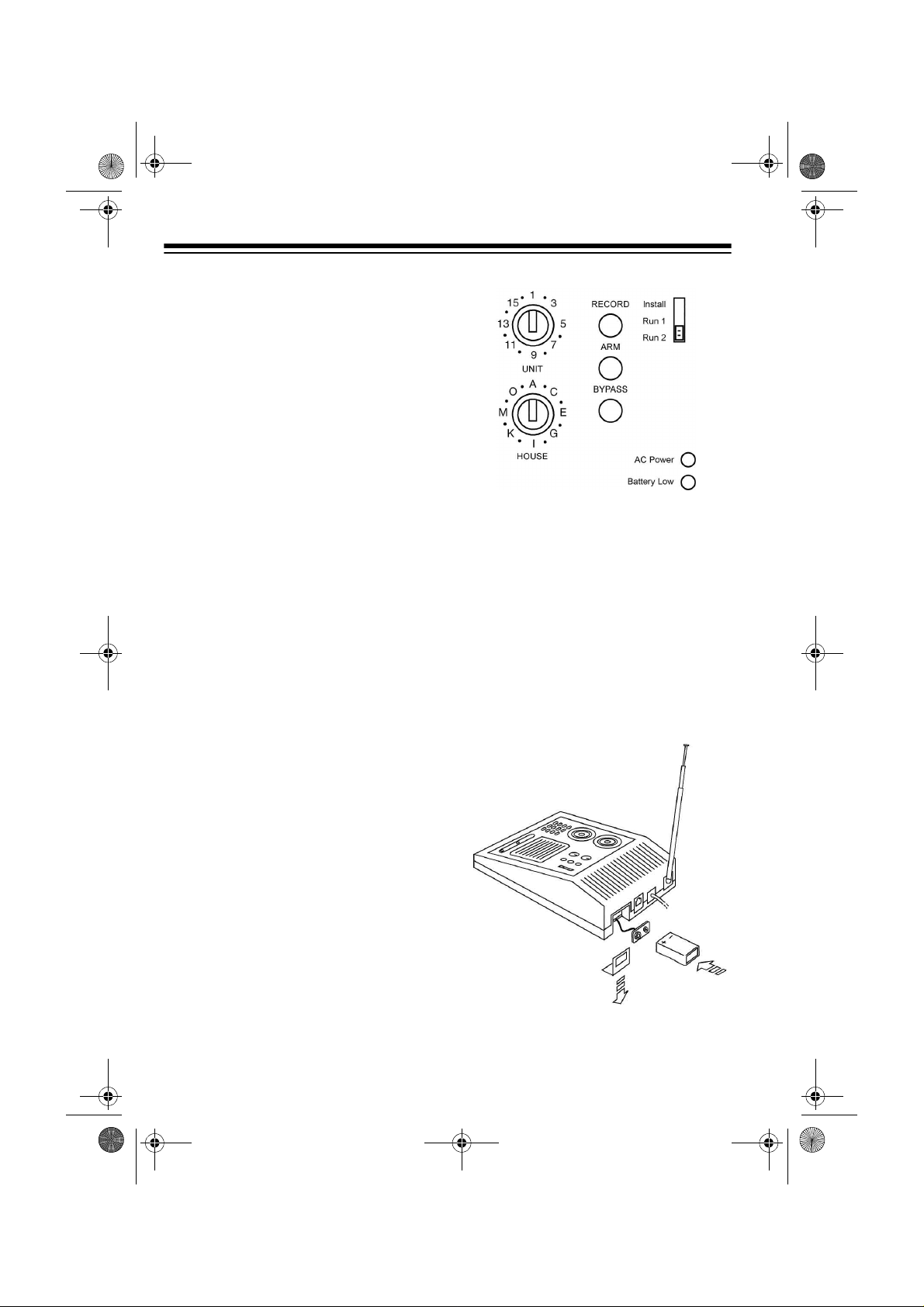
SETTING UP THE
CONSOLE
1. Choose a location for the console
that is:
• close to a telephone jack so you
can easily connect the telephone dialer
3. Place the telescoping antenna in
an upright position and fully
extend it.
4. For backup power in case of an
AC power failure, place a 9-volt
alkaline battery in the battery
compar tment. See “Replacing th e
Console’s Battery” on Page 37.
• central to the doors/windows
you want to protect so all sensors are within range of the
console (100 feet)
• positioned where you can easily
check the zone indicators for
any problems, but not where an
intruder could easily see it
2. Set the house and unit code di als
on the console to
Note:
You can set the cons ole to
any house code, but you must
also set all accessories/sensors to
the same house code.
10
A1.
Page 11
49-2551AB.fm Page 11 Friday, February 19, 1999 3:41 PM
Note:
Be sure to install the
backup battery. If there is no battery and the console loses AC
power, you must re-initialize all of
the system’s accessories.
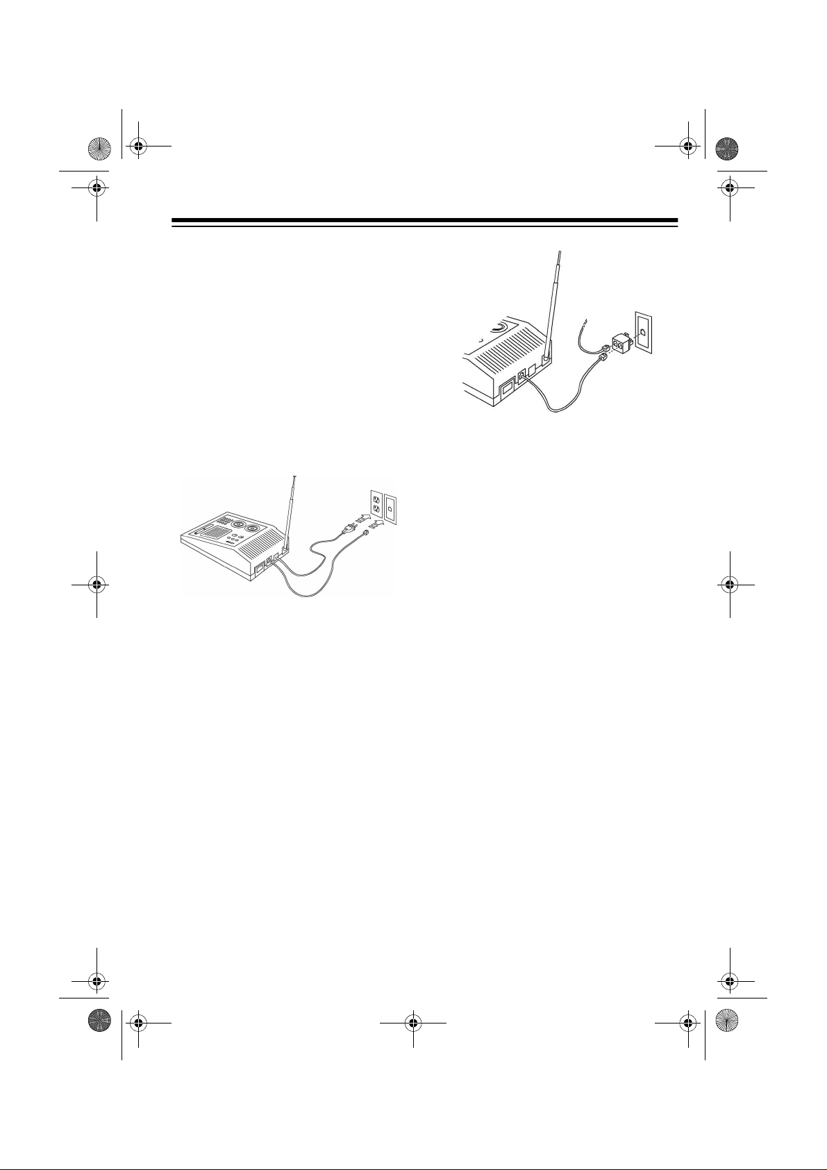
5. Plug the console into any standard AC outlet that is not controlled by an on/off switch.
6. Plug the telephone cord into the
console and plug the other end
into a modular phone jack.
• If you do not have a modular
phone jack, you can either updat e
the wiring yourself or have the
phone company do it for you.
RadioShack stores sell the jacks
and adapters you need. The
USOC number of the jack to be
installed is RJ11C for a baseboard
jack or RJ11W for a wall jack.
Notes:
• If you do not have an unused jack,
use the supplied duplex adapter.
For a baseboard jack, plug the
adapter into the jack; for a wall
jack, plug the adapter into the
console.
INSTALLING THE
KEYCHAIN REMOTE
CONTROL
1. Slide off the keychain remote c ontrol’s battery compartment cover.
Install two AAA alkaline batteries
in the compar tment, according to
the polarity symbols (+ and –)
marked inside. Then replace the
compar tme nt’s cover.
11
Page 12
49-2551AB.fm Page 12 Friday, February 19, 1999 3:41 PM
2. Press ARM on the remote control.
The indicator on the remote control blinks.
3. Set the console’s
RUN 2
switch to INSTALL.
4. Stand near the console and pr ess
ARM again. The indicator blinks
again, and the console chimes
and logs in the remote control.
5. Leave the console’s switch set to
INSTALL to install other accesso-
ries.
Notes:
INSTALL/RUN 1/
INSTALLING THE
HANDHELD REMOTE
CONTROL
1. Press the tab on the batter y compartment cover and lift off the
cover.
2. Install four AAA alkaline ba tteries
in the handheld remote control’s
battery compartment, according
to the polarity symbols (+ and –)
marked inside the compartment.
Still Missing-Paste in
this illustration at
Proof to Mass Print
stage.
3. Be sure the console’s
RUN 1/RUN 2
INSTALL.
4. Set the house code on the remote
control to the same letter as the
console.
5. Press
on the handheld remote control.
The console chimes.
ARM HOME or ARM AWAY
switch is set to
INSTALL/
• You can add any combination of
up to eight Plug ’n Power
remote controls.
• When you press a button,
TERY
lights on the remote c on-
trol to show the battery is good.
12
BAT-
Page 13

49-2551AB.fm Page 13 Friday, February 19, 1999 3:41 PM
Note:
If you do not hear a chime,
press the button beneath the
remote control’s label with a pencil. Then repeat this step.
6. Leave the console’s switch set to
INSTALL to install other accesso-
ries.
7. Replace the batter y compar tment
cover.
Note:
You can add any combination of
Plug ’n Power keychain s ( Cat. No. 49-
2591) or handheld remote controls
(Cat. No. 49-2551T), up to a total of
eight.
INITIALIZING THE
WIRELESS SENSOR
TRANSMITTERS
Follow these steps to initialize each
wireless sensor transmitter you plan to
use with your system.
1. Lift open thetransmitter’s battery comp artment
cover. Hold down
TEST, located to
the right of the
compartment,
long enough to
fully discharge
the sensor (about
3 seconds).
2. Install two AA alkaline batteries in
the compar tment accordin g to the
polarity sym bols (+ and –) marked
inside.
3. Be sure the console’s
RUN 1/RUN 2
INSTALL.
4. Press
TEST
switch is set to
on the transmitter
about 1 second. The indicator
blinks twice to generate a new
code.
INSTALL/
for
Note:
The indicator flashes rapidly during a violati on or after you
press
TEST. When the batteries’
voltage drops below around 2 .7V,
the indicator flashes twice when
TEST is pressed to indicate that
the batteries are weak.
13
Page 14

49-2551AB.fm Page 14 Friday, February 19, 1999 3:41 PM
5. Stand near the
console and
press
TEST. The
wireless sensor
transmitter’s indicator blinks.
6. Release
TEST.
The console
chimes and logs
in the newly generated code for
the wireless sensor transmitter.
The first available zone indicator on the console
lights.
7. Set
DELAY inside
the wireless sensor transmitter’s
battery compartment to
MIN to
protect a window
or to
MAX to pro-
tect a door. Then
close the battery
compartment’s
cover.
8. Place one of the supplied numbered stickers on the sensor to
show its zone number.
INITIALIZING THE
MOTION SENSOR
1. Press t he four dots on the batter y
compartment cover and slide the
cover down to remove it.
2. Install four 1.5V AA alkaline batteries inside the motion dete ctor’s
battery compar tment according to
the polarity symbols (+ and –) and
replace the cover.
3. Be sure the console’s
RUN 1/RUN 2
INSTALL.
switch is set to
INSTALL/
9. Leave the console’s switch set to
INSTALL to install other accesso-
ries.
Repeat Steps 1–8 for additional
wireless sensor transmitters.
14
Page 15

49-2551AB.fm Page 15 Friday, February 19, 1999 3:41 PM
4. Press TEST on the back of the
motion detector.
The console chim es, and the first
available zone indicator lights to
show the console has logged in
the motion detector.
If you do not hear a c hime, press
CODE with a pencil, then press
TEST again.
5. Looking at t he back of the motion
detector, set the switch on the left
side to
1.
6. Place one of the supplied numbered stickers on the motion
detector to show its zone number.
7. Leave the console’s switch set to
INSTALL to install other accesso-
ries.
8. Replace the batter y compar tment
cover.
INSTALLING THE LAMP
MODULE
When the alarm trips, la mps connected to lamp modules flash on and off for
the duration of the alarm. After 4 minutes (or when yo u disarm the alarm),
the lamps stop flashing and remain on.
If you arm the sy stem with an exit delay, lamp module s that are set to the
same House and Unit code as the console turn on during the ex it coun tdown
time.
You can also control lamp modules set
to this code from
OFF
on the keychain remote control, or
using
SECURITY LIGHT on the hand-
held remote.
Follow these steps to install a lamp
module.
1. Plug a lamp into the supplied lamp
module and plug the mod ule into
an AC outlet that is on the same
electrical circuit as the console.
Be sure the lamp’s on/off switch is
on.
2. Set the lamp module’s House and
Unit code dials to the same letter
as the console and the same
number (1, 2, 3, or 4) as th e button that will control it.
LIGHT ON and LIGHT
15
Page 16

49-2551AB.fm Page 16 Friday, February 19, 1999 3:41 PM
TESTING THE SYSTEM
After you have completed all of the
quick installation procedures, follow
these steps to test the system.
Note:
To avoid unnecessarily alarming
your neighbors, t ell th em y ou ar e test ing the syste m.
1. Set the
switch on the console to RUN 2.
REC/BUSY
2. Place each wireles s sensor transmitter’s magnet next to its magnetic switch with the arrows
pointing toward each other.
3. Place the motion detector on a
counter top within 100 feet of the
console.
INSTALL/RUN 1/RUN 2
lights for 15 seconds.
4. Move a wireless sensor transmitter’s magnet away from the magnetic switch.
When the system is not armed
and set to
RUN2, the console
emits a chime every time someone opens a door or window. The
system does not chim e when it is
set to
RUN 1.
Replace the magnet next to the
magnetic switch.
5. Press
ARM on a remote control,
and then move the magnet away
from the magnetic switch again.
The alarm sounds and the lamp
connected to the lamp module
flashes on and off. Press
DISARM
to turn off the alar m, and LIGHTS
OFF
to turn off the lamp. Replace
the magnet next to the magnetic
switch .
6. Press
ARM AWAY on the remote
control, then walk acro ss the path
of the motion det ector’s lens. The
alarm sounds and the lamp connected to the lamp module flashes
on and off. Press
DISARM to turn
off the alarm. The cons ole chi mes
twice. Press
LIGHTS OFF to turn
off the lamp.
16
Page 17

49-2551AB.fm Page 17 Friday, February 19, 1999 3:41 PM
MOUNTING ACCESSORIES
MOUNTING THE
WIRELESS SENSOR
TRANSMITTERS
You can install any combination of
wireless sensor transmitters (Cat. No.
49-2585) and motion detectors (Cat.
No. 49-2589), in up to 16 zones.
Follow these steps to mount each wireless sensor transmitter.
1. Set the
switch on the
wireless sensor
transmitter to
to protect a window or to
protect a door.
Note:
setting allows
you to arm a sensor with a 60second exit delay
and a 30-second
entry delay (see
“Instant/Delay
Mode” on Page
26).
The
DELAY
MIN
MAX to
MAX
are hidden from view or easily
accessible (including basement
windows).
Note:
magnetic switch are already connected. If the wire is too long, you
can shor ten it by cutting it to the
length required, stripping the
ends, and re-connecting it to the
magnetic switch.
3. Remove the sensor’s batteries
and attach it to the wall using the
supplied screws, or use doublesided mounting tape (Cat. No. 64-
2361).
First attach the sensor’s back
cover to the wall, then slide the
sensor onto the cover. Replace
the batteries (if you removed
them) and close the batter y compartment door.
4. Align the arrows on the switch and
magnet, and install t he switch and
magnet using the suppli ed sc rews
or double-sided mounting tape.
The supplied sensor and
When set to
immediately triggers the alarm
when a window opens, even if you
armed the system in the delay
mode.
2. Select a location for the wireless
sensor transmitter. We recommend that you purchase enough
sensors to protect the front and
back door and any windows that
MIN, the sensor
17
Page 18

49-2551AB.fm Page 18 Friday, February 19, 1999 3:41 PM
Notes:
• If you mount magnetic switches
on metal doors or frames,
ensure that they are no more
3
than
/16 of an inch apart. On
wooden surfaces, they can be
3
up to
/8 of an inch apart.
• Do not mount the magnet
directly onto a m etal surface. If
necessary, use a wood or plastic spacer.
• For sliding doors/windows, it is
best to mount the magnet and
switch at the bottom of the window. This way, the magnet will
make a “clean break” from the
switch when the window is
opened.
Notes:
• To protect mo re than one door or
window with a single sensor, use
NC-type (Normally Closed) magnetic switches and loop them in
series from on e d oor o r win dow t o
the next using 18-gauge wire.
Then connect both ends of the
loop to the sensor.
• The RadioShack Wireles s Sen-
sor Transmitter (Cat. No. 49-
2585) has an NC magnetic
switch and is compatible with
your security console.
5. Open the door or window. The
light on the se nsor turns on each
time you open the door or window.
Repeat Steps 1–5 for any additional
sensors you want to install (in up to 16
zones).
18
MOUNTING THE MOTION
DETECTO R
Motion detectors a re designed to detect motion in a specific area of your
home. For example, you might want to
protect the area around a s tereo system, jewelry box, or wall safe.
Page 19

49-2551AB.fm Page 19 Friday, February 19, 1999 3:41 PM
The supplied motion detector can
“see” up to a distanc e o f ab out 40 feet
with a 90 degree field of view. It can be
placed up to about 100 feet away from
the console.
Zone D
Zone C
Approx 40 ft.
Zone B
Zone A
Secure the bracket to the detector’s
bottom using the supplied machine
screw. Then secure the bracket to the
wall. Finally, loo sen the screw on the
hinge and adjust the detector to be level, then tighten the screw to hold th e
detector in position.
Right
Wrong
For the best coverage, place the motion detector at a he ig ht o f 6 f eet, then
position the lens so an intruder walks
across its path rather than toward it.
6 Feet
You can place the motion detecto r on
a counter top or use the included
mounting bracket. The bracket lets you
swivel the motion detec tor for the be st
coverage.
Note:
The motion detector senses motion by detecting temperature changes. To help prevent false alarms, do
not place the motion detector near a
heating or air conditioning vent.
Direction of
Entry
Less Sensitive Direction
19
Page 20

49-2551AB.fm Page 20 Friday, February 19, 1999 3:41 PM
Looking at the back of th e motion detector, set the switch on the left side to
1 (most sensitive) or 2 (less sensitive).
When set to
the alar m if
When set to
must detect two movements or continuous movement within a short time before it trips the alarm (this makes it less
sensitive to pets).
1, the motion detector trips
any
movement is detected.
2, the motion detector
To use the tape, place it over the lower
zones of the detector’s lens .
TESTING THE MOTION
DETECTOR
The motion detector includes a special
test mode. Follow these s teps to test
the motion detector.
1. Set the sensitivity switch on the
back of the motion detector to
2. Hold down
the motion detector until the indicator on the front flashes twice.
TEST on the back of
1.
MAKING A PET ZONE
If you have a pet, you can help reduce
the chance the pet will cause a false
alarm by blocking the motion detector’s lower zones with the supplied
piece of masking tape.
20
Page 21

49-2551AB.fm Page 21 Friday, February 19, 1999 3:41 PM
3. Release TEST and wait about 20
seconds.
4. Walk past the motion detector.
The indicator lights as you move
and turns off if you keep very still
or walk out of range of the detector.
Notes:
• If the range is low (less than 30
feet), check that the detector is
horizontal and at a height of at
least 5 feet from the ground.
• The motion detector automatically switches back to normal
operation after 2 minutes in the
test mode. If you want to switch it
back sooner, press the
TEST but-
ton.
To test the alarm, arm the console and
wait about 45 seconds. Then walk in
front of the motion detector and check
that the alarm is triggered.
After the motion detector triggers the
alarm, it automatically “locks out” for
about 45 seconds to save battery power.
21
Page 22

49-2551AB.fm Page 22 Friday, February 19, 1999 3:41 PM
SETTING UP THE TELEPHONE DIALER
The telephone dialer dials a friend or
neighbor (for example) and plays a
message in the following situations:
• when you press
hand-held remote control wi th the
system armed
• when you press
together on the keychain remote
control with the system armed
• when a wireless sensor transmit ter or motion detector connected
to the system reports a violation
while the system is armed
When the console plays its message,
the person contacted can press any
number on a touch-tone phone and
listen-in to your home to determine
the problem. The alarm stops when
the person contacted presses a button on the phone.
If no one answers at the number called
within about 48 seconds, or if someone
answers but does not press a number,
the console calls the next nu mber (up
to four phone numbers).
Notes:
• If the person you choose to accept
calls from your system does not
have touch-tone servic e, they can
use a touch-tone pocket dialer,
such as Cat. No. 43-145 or 43-
146.
PANIC on the
ARM and DISARM
• If the person tries to c all you after
the console has already begun
dialing other numbers, the caller
hears a busy signal.
• About 75 seconds after the listener presses a number, the alarm
resumes for 2–3 minutes.
• The console co ntinue s d ial in g an d
repeating its mes sage until it gets
a response. If it receives no
response within 4 minutes, the
alarm stops and the console stops
dialing.
• To stop the console from dialing
before 4 minutes have passed,
pick up any phone on the same
line. After you hear the first r ing o f
the number currently bei ng dia led ,
press
0. Stay on the line to speak
to whomever answers, and wait 2
minutes (for the console to
release the phone line) before
pressing any other keys on the
remote control or console or
attempting to dial another number.
SETTING UP PHONE
NUMBERS
Notes
:
• You should program the console
to call a friend, relative or neighbor who can listen-in to your home
to determine if there is a real problem. The person can then call the
police if necessary, or call you
back to see if everything is fine.
22
Page 23

49-2551AB.fm Page 23 Friday, February 19, 1999 3:41 PM
• You should
not
program the console to dial the police directly,
unless your local police department has a speci al line for emergency dialers.
When programming eme rgency numbers and/or making test calls to em ergency numbers:
• Remain on the line and briefly
explain to the dispatcher the reason for the call.
• Perform such activities in off-peak
hours, such as early morning or
late evenings.
Notes:
• The security console is intended
for use only with residential pho ne
systems.
• You can program a maximum of
16 digits. This allows 10-digit dial ing (area code plus number)
which is now required in some
metropolitan areas. For practical
purposes, we do not recommend
programming a long-distance
number.
Follow these steps to store up to four
emergency phone numbers.
1. Set the switch
on the bottom
of the console
to
TONE or
PULSE, based
on the type of
phone service
you have.
2. Set
3. Press
INSTALL/RUN 1/RUN 2 on the
console to
INSTALL.
PROG.
4. Enter the f irst phone number that
you want the console to ca ll i n the
event of a problem.
5. Press
6. Press
MEM.
1 to store the phone num-
ber in memory location 1.
Press
PROG and enter the second
phone number; then press
MEM
and 2. Pres s PROG and enter the
third phone number; then press
MEM and 3. Press PROG and
enter the fourth phone number;
then press
MEM and 4.
Notes:
• If you only want to program one
phone number, just enter the
same number in every memo ry
location.
• If you store only one emer-
gency number in all four memory loca tions, there is a longer
delay between each time the
console calls the number back.
Repeat Steps 1–6 to change a p hone
number.
23
Page 24

49-2551AB.fm Page 24 Friday, February 19, 1999 3:41 PM
RECORDING A VOICE
MESSAGE
Follow these steps to record your voice
message. For example,
possible burglary in progress at (address). Please press
call the police if you confir m there is a
problem.
Notes:
• Your message s hould instruct the
person to press any number on
their touch-tone phone. If the listener presses a number, the alarm
stops and they can l isten-in for 75
seconds.
• If the emergency dialer reaches
an answering machine, it plays its
message just as it woul d if someone picked up the phone. However, since the answering machine
cannot trigger the “ listen-in” function and stop the alar m, the dia ler
continues dialing and playing its
message.
There is a
0
to listen-in, then
2. Press RECORD. The REC/BUSY
light turns on.
3. Speak c lea rly into the mi cr op hon e
on the front of the console. You
can record a message up to 15
seconds long. After 15 seconds,
REC/BUSY
Note:
before you try to initialize any
accessory.
4. Plug the supplied earphone into
the jack on the side of the console.
turns off.
Be sure
REC/BUSY
is off
1. Set
console to
24
INSTALL/RUN 1/RUN 2 on the
INSTALL.
5. Set
INSTALL/RUN 1/RUN 2 on the
console to
console plays back your message
through the earphone.
Note:
sounds better when it is played
back over the phone line.
RUN 1 or RUN 2. The
The message usually
Page 25

49-2551AB.fm Page 25 Friday, February 19, 1999 3:41 PM
6. If you want to hear the message
again, set
INSTALL/RUN 1/RUN 2
on the console to INSTALL and
then back to
RUN 1 or RUN 2.
Repeat Steps 1–6 to change the mes sage.
TESTING THE DIALER
1. Set INSTALL/RUN 1/RUN 2 on the
console to
2. Call your friend o r neighbor to let
them know you are going to test
the system.
3. Press
a keychain remote contro l) to ar m
the system. Then trip the panic
alarm by pressing
ARM
chain remote control.
The console sounds its alarm,
lamps attached to remote modules flash on and off, and the telephone dialer begins dialing and
playing its message. If the person
called does not answer within
about 48 seconds, or answers but
does not press a number, the console calls the next number (up to
four phone numbers).
RUN 1.
ARM on the console (or on
ARM and DIS-
at the same time on a key-
4. Press
DISARM on
the remote control to turn off the
system and stop
the dialer. Press
LIGHTS OFF on
the remote control to turn off
lights connected
to modules.
25
Page 26

49-2551AB.fm Page 26 Friday, February 19, 1999 3:41 PM
OPERATION
ARMING/DISARMING
THE SYSTEM
You can arm the system three ways:
•Set
INSTALL/RUN 1/RUN 2 on the
console to
press
•Set I
NSTALL/RUN 1/RUN 2 on the
console to
press
on the handheld remote control.
See “Arm Away/Arm Home” and
“Instant/Delay Mode.”
•Set
INSTALL/RUN 1/RUN 2 on the
console to
press
remote control.
The only difference between
and RUN 2 is that when the system i s
set to
RUN 2 and
sole sounds a pleasant chime when
you open a door or window. When it is
set to
RUN 1, there are no chimes.
The console beeps once when you
arm it. When the system is armed, the
RUN 1 and RUN 2 setting have the
same effect: opening a door or window
with a sensor attached or tripping a
motion detector sets off the alarm.
To disarm the system, press
on any remote control. The console
beeps twice.
26
RUN 1 or RUN 2 and
ARM on the console.
RUN 1 or RUN 2 and
ARM AWAY or ARM HOME
RUN 1 or RUN 2 and
ARM on the keychain
RUN 1
not
armed, the con-
DISARM
Arm Away/Arm Home
All wireless sensor transmitters and
motion detectors a rm when y ou press
ARM AWAY on the handheld remote
control. If you pr ess
ARM HOME, only
doors and windows a rm. This lets yo u
arm the system at n ight without accidentally tripping the motion detector(s)
yourself when you move around the
house.
Instant/Delay Mode
The ENTRY switch on the handheld re-
mote control lets you ar m the system
with or without an exit/entry delay.
With
ENTRY on the handheld remote
set to
INST ANT (and DELAY on the sen-
sor(s) set to
arms and the alarm immediately trips if
a wireless sensor transmitter or motion
detector reports an intrusion.
With
ENTRY on the handheld remote
set to
exit delay and a 30-second entry delay
before the system arms or trips. A
warning chime sounds dur ing the delay period.
MIN), the system instantly
DELAY, you have a 60-second
Page 27

49-2551AB.fm Page 27 Friday, February 19, 1999 3:41 PM
Notes:
• The supplied motion detector
(Cat. No. 49-2589) only operates
INSTANT mode.
in the
If you want to use the exit/entry
delay feature, you can use
another motion detector (Cat. No.
61-2614) instead of the one supplied with this system. However,
the
ARM HOME feature might not
work.
• You must set the switch inside the
wireless sensor transmitter’s battery compartment to
MAX in order
for it to arm in the delay mode.
When set to
MIN, the sensor
immediately arms, regardless of
whether the handheld remote control is set to
• The
ARM button on the console
DELAY or INSTANT.
automatically arms the system in
the
DELAY mod e.
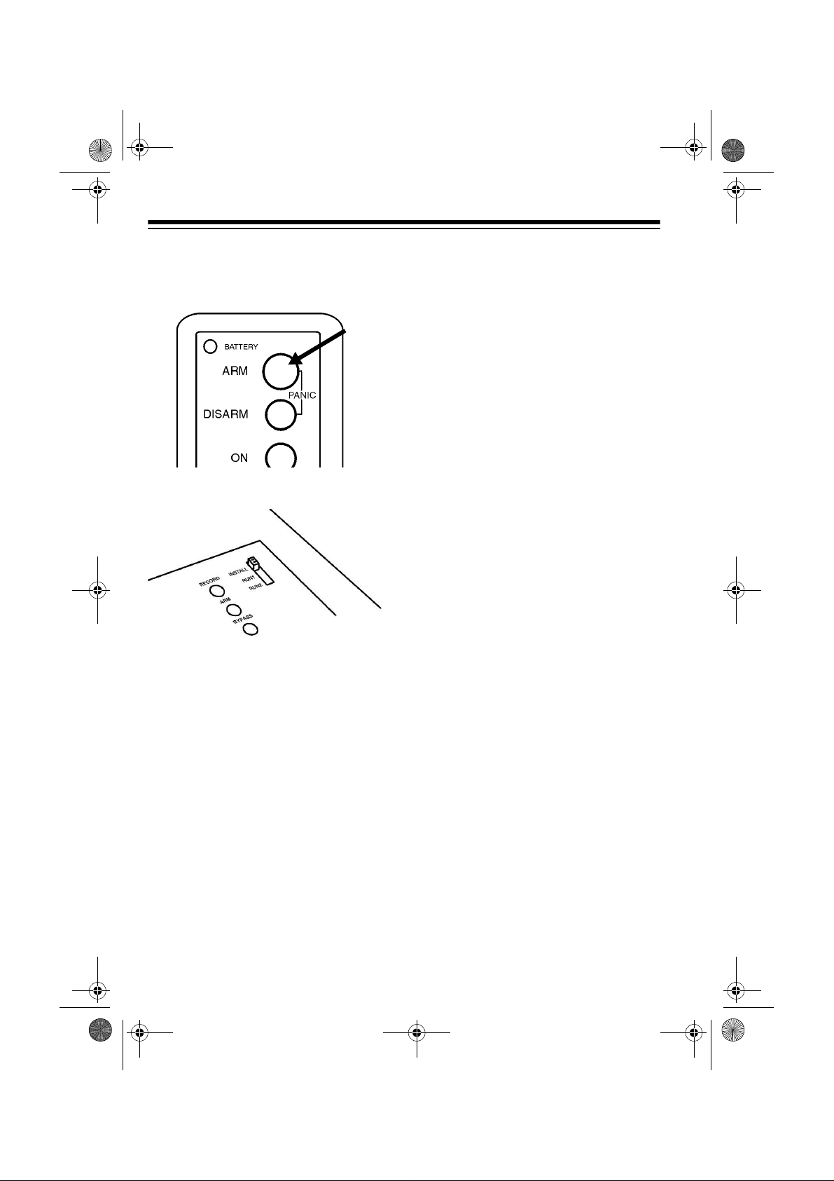
USING THE PANIC
ALARM
Pressing PANIC on the handheld remote control, or
ARM and DISARM at
the same time on the keychain remote
control, causes the console’s alarm to
sound, even if the system is not armed.
Note:
The telephone dialer does not
dial out unless the system is armed.
ZONE INDICATORS
All sensors and motion detectors report to the console about every 90 minutes. If the console does not rece ive a
signal from a sens or within 4 hours, it
reports a problem wit h that sensor by
slowly flashing its zone indicator.
• The keychain remote control only
arms the system in the
INSTANT
mode.
• Other separately purchased
remote controls might arm the
system only in either the
INSTANT mode. See the remote
DELAY or
control’s owner’s manual.
The console’s zone status indicators
show four conditions for Z ones 1–8.
27
Page 28

49-2551AB.fm Page 28 Friday, February 19, 1999 3:41 PM
Reading the Status of
Zones 1–8
Steady On
•
open.
Steady Off
•
closed.
Slow Flashing
•
transmitter is repor ting a problem
(such as a low battery).
Fast Flashing
•
transmitter reported a problem
(such as an open window or a low
battery) and you presse d
on the console (see “Trouble
Alarm”).
— door or window is
— door or wind ow is
— wireless sensor
— wireless sensor
BYPASS
Trouble Alarm
If you hear a repetitive trouble alarm
when you try to arm the system, this indicates that there is a problem.
The system does not arm until you:
Correct the Problem
•
DISARM to stop the trouble ala rm.
Check the zone reporting the
problem to see if a door or window
is open or a sensor’s battery is
dead. Then arm the system again.
— Press
Ignore the Problem
•
BYPASS on the console while the
trouble alarm is sounding.
The indicator(s) for the problem
zone(s) flash rapidly. Press
HOME/ARM AWAY
tem. The problem zone(s) are not
protected, but all other zones arm
Note:
If you bypass an open window or
door and arm the system, then later
close the window or door, that zone
then arms.
— Press
ARM
to arm the s ys-
Reading the Status of
Zones 9–16
If there is a proble m with zones 9–16 ,
the console does not sh ow a flashing
zone light, but you hear the trouble
alarm if you try to arm the system.
Hold down
The indicator li ghts show which zone
(9–16) is reporting the problem. I f you
do not want to bypass the problem,
correct it and arm the system again.
BYPASS on the console.
28
Page 29

49-2551AB.fm Page 29 Friday, February 19, 1999 3:41 PM
Other Console Indicators
BATTERY LOW (Steady)
•
tery in console is low or needs
replacement.
ARMED (Steady)
•
system is armed.
— indicates
— bat-
DURING AN ALARM
When there is a violation, the console
sounds a loud ( 95 dB ) sir en fo r 4 m in-
ARMED
utes,
tor for the affected zone lights steadily.
The dialer begins calling its emergency
numbers and playing its message, and
lights connected to lamp modules flash
on and off during the alarm.
flashes, and the indica -
there was a violation.
and the zone indicator fo r the violated
zone lights steadily.
Press
LIGHTS OFF to st op th e flash ing
indicator and turn off the zone light and
lamp modules.
ARMED
flashes
CONTROLING PLUG ’N
POWE R MODULES
Turning Modules ON/OFF
Use the four ON/OFF buttons on the
handheld remote control to control
lights connected to Plug ’n Power modules. Set the modules to the same
house code as the console. Set the
modules’ unit cod es to 1, 2, 3, or 4 t o
correspond to the handheld remote
control’s buttons .
AFTER AN ALARM
When you disarm the system after an
alarm (or about 4 minutes after the
alarm trips), the cons ole’s siren turns
off, but the lights connected to lamp
modules remain on to let you know
29
Page 30

49-2551AB.fm Page 30 Friday, February 19, 1999 3:41 PM
Using SECURITY LIGHT
Use the SECURITY LIGHT button on the
handheld remote control to tur n on/off
a light module set t o the same house
and unit code as the console.
Using BRIGHT/DIM
Use the BRIGHT/DIM button on the
handheld remote control to brighten or
dim lights connected to Plug ’n Powe r
modules.
Turn on the module by pressing the remote control
sponds to the module’s unit code.
Then press and hold
the remote control until the light reaches the desired brightness.
ON button that corre-
BRIGHT or DIM on
RESETTING THE
CONSOLE
30
To remove all sensors and phone
numbers from memory, unplug the
console and remove the battery. Then
plug the console back in.
Page 31

49-2551AB.fm Page 31 Friday, February 19, 1999 3:41 PM
TROUBLESHOOTING
If you experience problems with your security console or accessories, try correcting
the problem as suggested in this section. If you cannot correct the problem, contact
your local RadioShack store for assistance.
Problem Solution
The system does not arm. Check that
in the
RUN 1 or RUN 2 position.
If you are using a remote control to arm the system,
check that the battery indicator on the remote control turns on when you press
remote control or
handheld remote c ontrol. Replace the battery and
re-initialize the remote control, if necessary.
A zone indicator flashes
slowly.
One of the sensors/motion detectors has not reported in during the past 4 hours.
Check the battery in the sen sor/motion de tector to
see if it needs to be replaced, or bypass the zone.
A zone indicator flashes
rapidly.
You pressed
system while a sensor/mo tio n de tec tor was repo rt ing a problem. Correct the problem. The zone arms
automatically when the problem is corrected.
You hear a repetitive trouble alarm when you try to
arm the system, and it does
not arm.
Check the zone indic ators. If a door or window is
open, its zone indicat or is on. If there is a probl em
with a sensor or motion detector, its zone indicator
flashes slowly. You can correct this two ways:
•Press
sor transmitter is working properly and that
you have not left a door or window open. Then
arm the system.
INSTALL/RUN 1/RUN 2 on the console is
ARM on the keychain
ARM HOME/ARM AWAY on the
BYPASS
DISARM. Check that each wireles s sen-
on the console to arm the
• While the trouble alarm is sounding, press and
hold
BYPASS on the console to override the
problem zone (its zone indicator then flashe s
rapidly). Then arm the system.
31
Page 32

49-2551AB.fm Page 32 Friday, February 19, 1999 3:41 PM
Problem Solution
The alarm trips when you
enter the house befor e you
have time to disarm it.
Arm the system in the delay mode. Se t the
switch on the entry door sensor to MAX. Set the EN-
TRY
switch on the ha ndheld remote con trol to DE-
LAY
, and then press ARM HOME or ARM AWAY on
the handheld remote control.
DELAY
You cannot turn lights on or
off using the
LIGHT OFF buttons on the
LIGHT ON or
remote.
You open a door or window
and the alarm does not trip.
Make sure you se t th e hou se an d uni t c od e o n the
module(s) to the same letter and number as the
console.
If you have more than one console, ensure that you
set both to the same house and unit code.
Be sure the light you are trying to control is plugged
in and has its on/off sw itch in the on position, and
that its bulb is good.
Plug the module into another outlet on the same
electrical circuit as the console.
Check that the battery indicator on the remote control comes on when you pr ess a button. Replace
the battery and re-initialize the remote control, if
necessary.
Check to see if the system is armed.
Be sure
to
Press
INST ALL /RUN 1/R UN 2 on the console is set
RUN1 or RUN 2.
TEST on the wireless sensor transmitter and
see if the alarm trips. If the alarm does not trip, see
if the sensor indicato r comes on when you press
TEST. If the indicator does not come on, replace the
battery and re-initialize the sensor, if necessary.
32
Page 33

49-2551AB.fm Page 33 Friday, February 19, 1999 3:41 PM
Problem Solution
You do not hear a chime
from the console w hen you
press
ARM to install a re-
mote.
You do not hear a chime
from the console w hen you
press
TEST to install a wire-
less sensor transmitter or
motion detector.
Check if you can a rm the system when
RUN 1/RUN 2
2
. If you can, the remote control is already installed
on the console is set to RUN 1 or RUN
INSTALL/
and no further action is necessary. If not:
1. Set
2. Press
INSTALL/RUN 1/RUN 2 on the console to
INSTALL.
CODE (located beneath the label on the
remote control) with a p encil, then press
ARM
again.
With
INSTALL/RUN 1/RUN 2 on the console set to
RUN 2 , check that the console chimes when you
press
TEST on the sensor or motion detector. If it
does, the sensor or m otion detector is already installed and no further action is necessary. If not:
1. Set
2. Press
Note:
INSTALL/RUN 1/RUN 2 on the console to
INSTALL.
CODE on the sensor or motion detector
with a pencil, then press
TEST again.
If the sensor/motion detector is already installed, it is ins talled again into the next available
zone.
BATTERY LOW on the
console is on.
You lose your r emote control.
The system arms or disarms by itself.
Install or replace the console’s battery.
Purchase a replacement remote control (Cat. No.
49-2551T or 49-2591), and then completely reinstall your sys tem using different house and unit
codes to prevent someone else from using the lost
remote control.
A neighbor may have a compatible system. Reinstall the system using a different house code.
33
Page 34

49-2551AB.fm Page 34 Friday, February 19, 1999 3:41 PM
Problem Solution
The red light on the h andheld remote control stays
on during installation.
The red light on the sensor/
motion detector stays on
during installation.
ARMED
flashes. This indicates tha t th er e h as bee n a n i ntr usion. Al-
A motion detector causes
“false alarms.”
Press the button l ocated beneath the label with a
pencil and then press
ARM. If it still stays on, re-
move the battery, wait a few seconds, then replace
the battery. Press the button and then
Press
CODE, then press TEST on the sensor/mo-
ARM again.
tion detector. If it still stays on, remove the battery,
wait a few seconds, and then repl ace the battery.
Press
CODE, then press TEST again.
so, if a zone indicator is on, this indicates which
zone was viola ted. To turn the zone indicator off
and stop the armed in dicator from flashing, pres s
the
LIGHT ON or OFF button on a remote control. If
a zone indicator is not on, the violated zone is within zones 9-16. Press
BYP ASS on the console to see
which zone was tripped.
Motion detectors sense motion by detecting a
change in temperature; the refore, do not place the
motion detector near an air c ond iti oning o r he ati ng
vent.
Do not place it in a direct source of bright light, such
as sunlight.
The console does not dial
out.
The console does not play
back any message when
the phone is answered.
34
It could be detecting a pet’s movements. Place the
detector at a height of 6 feet, or se t the switch on
the back to 2 so it is less sensitive.
Check that you ha ve stored a phone number (see
“Setting up Phone Numbers” on page 22).
Check that the console is armed
Check that you have recorded a message (see
“Recording a Voice Message” on page 24).
Page 35

49-2551AB.fm Page 35 Friday, February 19, 1999 3:41 PM
Problem Solution
The console appears to be
“locked-up.”
REC/BUSY
If
console from
is on, you might have just switched the
INSTALL
to
RUN 1
or RUN 2. The console then plays back the 15 seconds of pre-recorded message. If you do not have the earphone
connected, you might think that the console is
locked-up. Wait 15 seconds until
REC/BUSY
light
turns off.
REC/BUSY
If
is not on, you might have just tested
the system. When the console dials out, and someone answers the phone and press es any key, the
console is put into th e lis ten mod e for 75 seconds.
If you immediately call t he person back or if they
call you, your phone will be busy. Press
DISARM on
the remote and wait for 75 seconds.
35
Page 36

49-2551AB.fm Page 36 Friday, February 19, 1999 3:41 PM
CARE AND MAINTENANCE
Your RadioShack Wire less Home Sec uri ty S ys tem is an exam pl e of s upe rior design and craftsmanship. The following suggestions will help you care for your security system so you can enjoy it for years.
Keep the console and accessories dry. If they gets wet, wipe them dry
immediately. Liquids might contain minerals that can corrode the electronic circuits.
Use and store the con sole and accessor ies only in normal temperature environments. Temperature extremes can shorten the life of electronic devices, damage batteries, and distort or melt plastic parts.
Keep the console and accessories away from dust and dirt, which can
cause premature wear of parts.
Handle the console and ac cessories gently and carefull y. Dropping
them can damage circuit boards and cases and can cause the console
and system to work improperly.
Use only fresh ba tteri es of the r equ ired s iz e a nd re co mm ende d typ e.
Batteries can le ak chemicals that damage your sys tem’s electronic
parts.
Wipe the console and acc essories with a damp cloth occas ionally to
keep it looking new. Do not use harsh chemicals, cleaning solvents, or
strong detergents to clean the console or any accessories.
Modifying or tamperin g with the console’s or accessories’ int ernal components
can cause a malfunction and might invalidate its warranty and void your FCC authorization to operate the system. If your console is not performing as it sh ould,
take it to your local RadioShack store for assistance. If the trouble is affecting the
telephone lines, the phone company can ask you to disconnect your console system until you have resolved the problem.
36
Page 37

49-2551AB.fm Page 37 Friday, February 19, 1999 3:41 PM
REPLACING THE
CONSOLE’S BATTERY
The console’s backup battery allows
the system to work during a power outage. A 9-volt alkaline battery provides
at least 12 hours of backup. BATTERY
LOW lights on the console when you
need to replace the backup battery, but
you should replace the batt er y at lea st
once a year.
Do not unplug the console from AC
power when you replace the battery.
Otherwise, the cons ole loses all memory of the installed wireless sensor
transmitters, motion de tectors and remote controls, and the v oice m essage
and stored numbers. You must then
set the
the console to
emergency message, re-program
emergency numbers, and then re-install all the wireless sensor transmitters, motion detectors and remote
controls.
INST ALL/RUN 1/R UN 2 switch on
INSTALL, re-r ecord your
REPLACING A
REMOTE’S BATTERIES
If the console does not respond to a remote control’s signal, re place the batteries in the remote control’s battery
compartment, according to the polarity
symbols (+ and – ) marked inside the
compartment.
After you replace the remote co ntrol’s
batteries, re-initializ e the remote control as described in “Installing the Keychain Remote Contro l” on page 11 or
“Installing the Handheld Re mote Control” on page 12.
Note:
When you press a button on the
keychain remote, BATTERY lights to
show the battery is good.
After replacing b atteries, follow these
steps to conf irm that the console still
recognizes the remote control.
1. Set
2. Press
If the system arms, the console recognized the remote control.
If the system did not arm:
1. Set
2. Press
INSTALL/RUN 1/RUN 2 on the
console to
INSTALL.
The remote control transmits a
random code to the c onsole. The
console acknowledges this with a
chime and logs in th e r em ote c ontrol. If you do not hear a chime,
press
press
RUN 2.
ARM on the remote control.
INSTALL/RUN 1/RUN 2 to
ARM on the remote control.
CODE with a pencil and then
ARM.
37
Page 38

49-2551AB.fm Page 38 Friday, February 19, 1999 3:41 PM
REPLACING A
WIRELESS
TRANSMITTER’S
SENSOR BATTERIES
If any of the console’ s zone indi cators
flash slowly, the wireless sensor transmitter or motion detector for that zone
has not reported in during the last 4
hours. This is most likely caus ed by a
dead battery in the wireless sensor
transmitter or motion detector.
Replace the wireless sensor transmitter or motion detector’s battery, and
then follow these ste ps to confi rm that
the consol e still recognizes it.
1. Set
2. Press
If the console chimes, it recognizes the
sensor or motion detector.
INSTALL/RUN 1/RUN 2 on the
console to
motion detector.
RUN 2.
TEST on the sensor or
battery in the wireless sensor transmitter when its zone light was
(low battery indicator), the wireless
sensor transmitter is assigned to the
next available zone.
To avoid this, remove the sens or’s ol d
battery and wait at least 4 hours before
installing the new one. This ensures
that the sensor is ass igned to i ts or iginal zone number.
not
flashing
INTERCOM SYSTEMS
Intercom systems which send voice
signals over existing electrical wiring
might interfere with the ability to control
modules from your security system
when the intercom is in use.
If the interc om system has its ow n separate wiring, it does no t cause a p roblem.
If you do not hear a chime when you
press
TEST:
1. Set
2. Press
The wireless sensor transmitter normally is assigned to the same zone
number as before you replaced the
battery. However, if y ou replaced the
38
INSTALL/RUN 1/RUN 2 on the
console to
transmitter transmits a code to the
console, and the console chimes
to confirm it accepted the code.
INSTALL.
TEST. The wireless sensor
Page 39

49-2551AB.fm Page 39 Friday, February 19, 1999 3:41 PM
FCC CAUTIONS
This equipment generates and uses
radio frequency energy, and if not in stalled and used properly, that is, in
strict accordanc e with the ma nufacturer’s instructions, may cause interference to radio and television reception.
It has been type tested and found to
comply with the limits for remote control security devices in accordance
with the specifications in Part 15 of
FCC Rules
vide reasonable protection against
such interference in a residential installation. Howeve r, there is no guarantee that interference will not occur in
a particular installation.
If this equipment does cause interference to radio or television reception,
which can be determined by unplugging the equipment, the user is encouraged to try to correct the inte rference
by one or more of the following mea sures.
, which are designed to pro-
LIGHTNING
Your security console dialer has builtin protection ci rcuits to redu ce th e ri sk
of damage from surges in telephone
line and power line current. These protection circuits meet or exceed the
FCC requirements. However, lightning
striking the telephone or power lines
can damage your console dialer.
Lightning damage is not common.
Nevertheless, if you live in an area that
has severe electrical storms, we suggest that you unplug you r consol e an d
rely on its battery power during storms
to reduce the possibility of damage.
• Reorient the anten na of the radio/
TV experiencing the interference.
• Move the console away from the
radio/TV.
• Plug the console int o an outlet on
a different electrical circuit from
the radio/TV experiencing the
interference.
If necessary, contact your local RadioShack store f or additional suggestions.
39
Page 40

49-2551AB.fm Page 40 Friday, February 19, 1999 3:41 PM
Limited Ninety-Day Warranty
This product is warranted by RadioShack against manufacturing defects in material and workm anship under normal use for ninety (90) days fr om the date of purchase from Ra dioShack c ompany-owned st ores
and authorized RadioSh ack franchisees and dealers. EXCEPT AS PROVIDED HEREIN, RadioShack
MAKES NO EXPRESS WARRANTIES AND ANY IMPLIED WARRANTIES, INCLUDING THOSE OF
MERCHANTABILITY AND FITNESS FOR A PARTICULAR PURPOSE, ARE LIMITED IN DURATION TO
THE DURATION OF THE WRITTEN LIMITED WARRANTIES CONTAINED HEREIN. EXCEPT AS PROVIDED HEREIN, RadioShack SHALL HAVE NO LIABILITY OR RESPONSIBILITY TO CUSTOMER OR
ANY OTHER PERSON OR ENTITY WITH RESPECT TO ANY LIABILITY, LOSS OR DAMAGE CAUSED
DIRECTLY OR INDIRECTLY BY USE OR PERFORMANCE OF THE PRODUCT OR ARISING O UT OF
ANY BREACH OF THIS WARRANTY, INCLUDING, BUT NOT LIMITED TO, ANY DAMAGES RESULTING FROM INCONVENIENCE, LOSS OF TIME, DATA, PROPERTY, REVENUE, OR PROFIT OR ANY
INDIRECT, SPECIAL, INCIDENTAL, OR CONSEQUENTIAL DAMAGES, EVEN IF RadioShack HAS
BEEN ADVISED OF THE POSSIBILITY OF SUCH DAMAGES.
Some states do not allow the limitations on how long an implied warranty lasts or the exclusion of incidental or consequential damages, so the above limitations or exclusions may not apply to you.
In the event of a product defect during the warranty period, take the product and the RadioShack sales receipt as proof of purchase date to any RadioShack store. RadioShack will, at its option, unless otherwise
provided by law: (a) correct the defect by product repair wit hout charge for parts and labor; (b) replace the
product with one of the same or sim ilar design; or (c) refund the purchase pric e. All replaced par ts and
products, and products on w hich a refund is made, become th e property of R ad ioS ha ck. New or r eco nd itioned parts and products may be used in the performance of warranty ser vice. Repaired or replaced
parts and products are warranted for the remainder of the original warranty period. You will be charged for
repair or replacement of the product made after the expiration of the warranty period.
This warranty does not cover: (a) damage or failure cau sed by or a ttr i butable to acts of God, abuse, accident, misuse, improper or abnorm al usage, failure to follow instructions, improper installation or maintenance, alteration, lightning or other incidence of excess voltage or current; (b) any repairs other than those
provided by a RadioShack Authorized Service Facility; (c) consumables such as fuses or batteries; (d)
cosmetic damage; (e) transportation, shipping or insurance costs; or (f) costs of product removal, installation, set-up service adjustment or reinstallation.
This warranty gives you specific legal rig hts, and you may also have other rights w hich var y from st ate to
state.
RadioShack Customer Relations, Dept. W, 100 Throckmorton St., Suite 600, Fort Worth, TX 76102
We Service What We Sell
3/97
RadioShack
A Division of Tandy Corporation
Fort Worth, Texas 76102
02A99 Printed in Hong Kong
 Loading...