

Rademacher 26400665 User guide
EN Operating and installation instructions for RADEMACHER DuoFern tubular motors ........................29
Applicable for the following series: RolloTube Intelligent Radio Small and Medium
Item numbers: 2640 06 65 / 2640 10 65 / 2660 10 65 / 2660 20 65 / 2660 30 65 / 2660 40 65 / 2660 50 65
Please note:
Site of installation:
.................................................................................................................................
Serial number
.................................................................................................................................
VBD 560-1 (09.13)
Please stick the enclosed label showing the radio code here:
i
STOP
Dear Customers,
With your purchase of this tubular motor, you have decided in favour of a quality
product manufactured by RADEMACHER. We would like to thank you for your confidence.
RADEMACHER tubular motors have been developed with the greatest possible
convenience in mind. Having applied uncompromising quality standards, and carried out
thorough testing, we are proud to be able to present you with this innovative product.
It’s brought to you by all the highly-qualified personnel
here at RADEMACHER.
EN
i
i
These instructions...
... serve to describe the installation, electrical connection and operation of RADEMACHER
DuoFern tubular motors of series RolloTube Intelligent Radio Small and Medium.
Before you begin work, please read these instructions through completely and follow all
the safety instructions.
Please store these instructions in a safe place and pass them on to any future owners.
Damage resulting from non-compliance with these instructions and safety instructions will
void the guarantee. We assume no liability for any consequential damage.
Key to symbols
Danger of fatal electric shock
This sign warns of danger when working on electrical connections, components, etc.
It requires that safety precautions be taken to protect the life and health of the person
concerned.
This concerns your safety.
Please pay particular attention and carefully follow all instructions marked with this symbol.
This symbol warns of malpractices that can result in personal injury
or property damage.
NOTE/IMPORTANT/CAUTION
In this way, we wish to make you aware of the following content in order to ensure
optimal functionality.
30

i
Contents
Dear Customers, ............................................................................................30
These instructions... .......................................................................................30
Key to symbols ..............................................................................................30
Figures .........................................................................................................32
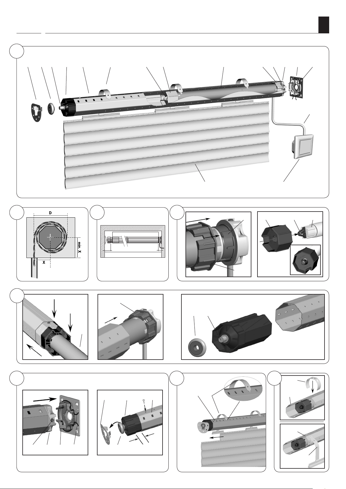
Key to the overall view (Figure a) ................................................................ 33
General safety instructions...............................................................................34
Proper use / operational conditions .................................................................. 34
Incorrect use .................................................................................................34
Functional description ..................................................................................... 35
Blockage detection function .............................................................................35
Obstacle detection function ..............................................................................35
Function of the shutter length compensation system ...........................................36
Function of radio code ....................................................................................36
Important assembly instructions .......................................................................36
Installation of the tubular motor ....................................................................... 37
Mounting the bearing (Figure ) ................................................................... 37
Determine the length of the rotating union (Figure ) ......................................37
Mounting / dismounting the adapter (Figure ) .............................................. 37
Mounting the catch with freewheel mechanism (Figure
Mounting the catch without freewheel mechanism (Figure
Dismounting the catch (Figure
Sliding the tubular motor into the rotating union (Figure ) ...............................39
Preparation for use of precision tubes (Figures
Inserting the bearing capsule (Figure ) .........................................................40
Mounting the motor into the bearing (Figure ) ..............................................41
Mounting the roller shutter casing (Figures g/h) ..........................................41
Mounting the roller shutter stopper or an end-rail (Figure 9) .............................. 41
Safety information regarding the electrical connection .........................................42
The motor cable (Figure j) ..........................................................................42
Electrical connection of the tubular motor (Figure k) ........................................43
Control with 1-pole switch (closer) (Figure l) .................................................43
Connection and use of the cord circuit setting unit
for end point setting (Figures m/n) ...............................................................44
End point adjustment......................................................................................44
Automatic configuration of the end points .......................................................... 45
Manual adjustment of end points .....................................................................46
Manually setting the upper end point and
automatically setting the lower end point ..........................................................46
Automatically setting the upper end point and
manually setting the lower end point ................................................................47
Manual setting of upper / lower endpoint with a cord circuit setting unit or
with an external switch ...................................................................................48
Manual setting of upper / lower endpoint with help of the
set button on the tubular motor .......................................................................49
Manually setting the upper / lower endpoints with DuoFern transmitters ..............49
Test run / modifying the end points..................................................................49
Configuring tubular motors ..............................................................................50
Loading factory settings during the commissioning process ...................................50
What to do if... ? ..........................................................................................51
Technical specifications ...................................................................................52
CE Mark and EC Conformity ............................................................................52
Connecting / disconnecting DuoFern transmitters ...............................................53
Connecting / disconnecting a DuoFern transmitter with the help of a set button ...... 53
Connect / disconnect the DuoFern central operating unit with the radio code .......... 54
Warranty conditions .......................................................................................56
) .................................................................. 38
) * ............................38
) ............................38
-
) ....................................39
EN
31
1
B C
A
L
i
(1) (2)
Figures
(4)
(5) (6) (8) (9) (10) (12) (13)(3) (11) (14)
(7)
(15)
(16)(17)
EN
2 3
= (D/2)
5
(5)
(8)
(9)
6
L = A - (B + C)
(10)
(5)
(4)(1)
(5)
4
7
(2) (3)
(5) (6)
(10)
(18)
(8) (7) (19)
(4)
8
(20)
SW 40
(5)
(11)
(12) (13) (14)
32
(20)
(2)
(6)

i
Key to the overall view (Figure a)
EN
(1) Counter bearing
(2) Ball bearings
(3) Axle pin on bearing capsule
(4) Bearing capsule
(5) Rotating union
(6) Mounting spring
(7) Retaining clip
(8) Catch
(9) Tubular motor
(10) Adapter
(11) Set button (transparent with LED)
(12) Drive head
(13) Drive end bearing
(14) Retainer
(15) Motor cable
(16) Controller (e.g. external switch)
(17) Roller shutter casing
(18) Limit ring
(19) Drive adapter
(20) Hook-in brackets
Please note:
Customer-specific scope of delivery
After unpacking please check the following:
◆ Check that the package contents matches the scope of delivery listed on the package.
◆ Check that the motor type corresponds to the specifications on the type plate.
33
General safety instructions
EN
Danger due to electric shock when working on all electrical systems.
◆ The electrical connection for the tubular motor and all work on the electrical systems
may only be undertaken by an authorised qualified electrician and in accordance with the
connection diagrams in these instructions, see pages 42/43/44.
◆ Carry out all installation and connection work only in an isolated, deenergised state.
Mortal danger in the event of failure to observe these instructions!
◆ Observe the regulations regarding installation in damp rooms.
◆ Especially observe DIN VDE 0100, parts 701 and 702 when installing in damp rooms.
These regulations contain mandatory protective measures.
The use of defective equipment can lead to personal injury and damage
to property (electric shocks, short circuiting).
◆ Never use defective or damaged equipment.
◆ Check the drive and mains cable beforehand for damage.
◆ Consult our customer service department (see page 56) in the event that you discover
damage on the equipment.
According DIN EN 13659, it is necessary to determine that the movement
conditions for the shutters are maintained in accordance with EN 12045.
The displacement must amount to at least 40 mm on the lower edge in the
rolled-out position with a force of 150 N in the upwards direction. In doing
so, it must be ensured that the extending speed of the shutters for the final
0.4 m is less than 0.2 m/s.
Potential risk to life and limb resulting from uncontrolled starting of
the drive.
Never attempt to manually stop the motor/shutters in the event of uncontrolled
movement. In such cases, switch off all power to the drive and take appropriate safety
precautions to prevent unintentional switching on. Arrange to have the system checked
by a specialist engineer.
Incorrect use leads to an increased risk of injury.
◆ Train all personnel to safely use the tubular motor.
◆ Do not allow children to play with the fixed control units.
◆ Do not allow children or persons with limited capabilities to use the fixed control units
or remote control systems.
For roller shutters:
◆ Watch the moving roller shutters and keep other people away from the area until
the movement has completed.
◆ Undertake all cleaning work on the roller shutters with the equipment disconnected
from the mains power.
For awning systems which can be operated out of sight of the operator:
◆ Awnings may not be operated if work is being carried out nearby (e.g. windows
being cleaned).
For automatically actuated awnings:
◆ Awnings must be disconnected from the power supply if work is being carried out
nearby.
Regular maintenance of awnings increases operational reliability.
◆ Check the awnings regularly for poor balance or damaged lines and springs.
◆ Have damaged awnings repaired by a specialist firm.
Contact with the drive housing can cause burns.
◆ The tubular motor gets hot during operation. Allow the motor to cool down prior to
undertaking any further work on the motor.
◆ Never touch the hot drive housing.
i
i
Proper use / operational conditions
Only use the tubular motors for opening and closing roller shutters
and awnings.
IMPORTANT
◆ In the event of outside installation the motor cable must be laid on a suitable empty
tube up to the junction box under observation of local electrical regulations.
◆ Only use the manufacturer’s original parts and accessories.
Only use tubular motors which correspond to the local conditions in
terms of their output. Incorrectly dimensioned tubular motors can lead
to damage:
◆ An insufficiently dimensioned tubular motor can be damaged due
to overloading.
◆ An excessively dimensioned tubular motor can cause damage, for
example, to the roller shutters and roller shutter casing when
configuring the automatic end-point setting.
Consult a specialist dealer when selecting the tubular motor and observe our tractive
force specifications on our website: www.rademacher.de
Incorrect use
Operating conditions
◆ A 230 V/50 Hz power supply, together with a site-provided isolating device (fuse,
MCB), must be permanently available at the installation location.
◆ The installation and operation of the DuoFern radio system and its components is
only permitted for those systems and devices where a malfunction in the transmitter
or receiver would not cause a danger to personnel or property or where this risk is
already covered by other safety equipment.
34
Never use the tubular motor:
For systems with increased safety-relevant requirements or where there is an increased risk
of accidents. Such use would require additional safety equipment. Observe the respective
statutory regulations for the installation of such systems.
Never use the DuoFern radio system or its components for:
systems with increased safety-relevant requirements or where there is an increased risk
of accidents. Such use would require additional safety equipment. Observe the respective
statutory regulations for the installation of such systems.

i
Functional description
EN
The RADEMACHER DuoFern RolloTube Intelligent Radio series of tubular motors are designed
for opening and closing roller shutters and awnings.
The internal DuoFern interface enables the motor to be integrated into a DuoFern radio
network, making it possible to configure and control many automatic functions remotely
with the help of a DuoFern transmitter (e.g. the DuoFern central operating unit).
An additional switch can be connected to the tubular motor locally in order to enable
manual operation.
These tubular motors are equipped with the new Safe-Drive system for position detection,
torque monitoring and obstacle detection. The drive’s compact design and fully automatic
end point configuration ensures for straightforward and convenient installation.
The RolloTube Intelligent Radio series impresses in daily operation with automatic roller
shutter compensation as well as the blockage and obstacle detection system (with reversing
function), ensuring maximum safety and gentle operation.
General tubular motor functions:
◆ Commissioning with a single run command. Self-learning motor with fully automatic
end point configuration.
◆ Safe-Drive method for precise positioning, torque monitoring and obstacle detection.
◆ Blockage and obstacle detection including reversing function.
◆ Obstacle detection can be arbitrarily configured thanks to the new snap-in FlexiClick
system.
◆ Maintenance free end points thanks to automatic shutter length compensation system.
◆ Quick and easy installation thanks to the new shorter design.
◆ Optionally available: Universal RT ConfigTool for individual configuration of the
motor parameters.
Short description of the DuoFern radio system
The DuoFern radio system enables bidirectional data exchange between the various
participants of a DuoFern radio network. All of the switching commands from the DuoFern
transmitter (e.g. DuoFern central operating unit) are received and acknowledged by the
DuoFern components (actuators / sensors), insofar as both devices are interconnected.
Tubular motor functions in combination with DuoFern transmitters
DuoFern environmental sensor; Item no 3200 00 64
DuoFern manual central operating unit; Item no 3481 00 60
RolloTron Pro Comfort DuoFern; Item no 1523 45 11
DuoFern manual transmitter standard; Item no 3248 03 66
Manual control (on/off)
AUTO/MANU - switchover
Timed program
Timer on / off
Random function
Twilight program (mornings)
Twilight program (evenings)
Darkness control
(mornings and evenings) on / off
Solar program
Automatic solar function on / off
Set solar position
Wind program
Automatic wind function on / off
Set direction of rotation for wind
Rain program
Automatic rain function on / off
Set direction of rotation for rain
Set ventilation position
Set direction reversal
Start connection test
End point adjustment radio controlled
Radio code support
(e. g. log on and log off with radio code)
● ● ●
● ●
● ●
● ●
● ●
● ●
● ● ●
● ●
● ●
● ●
●
●
●
●
●
●
● ●
● ●
● ●
●
●
●
i
i
Blockage detection function
The tubular motor stops and automatically shifts into the opposite
direction (reversing) in the event that an obstacle is detected while
opening (e.g. if a roller shutter is iced-up).
NOTE
Do not move iced-up roller shutters and rectify the fault or remove the obstacle.
Obstacle detection function
The tubular motor stops and automatically shifts briefly in the opposite
direction (reversing) in the event that the roller shutter hits an obstacle
while closing.
Requirements for correct obstacle detection:
◆ The catch with freewheel mechanism must be mounted (see Fig. 4.a, page 38).
◆ The roller shutter must be mounted to the rotating union with the fastening springs
or with the fixed shaft connector.
◆ Roller shutters must always run vertically in the guide rails of the window.
35

i
Function of the shutter length compensation system
EN
i
The shutter length compensation system is active subsequent to every
automatic learning process for the upper end point. Afterwards, the
tubular motor no longer runs fully against the upper end point in order
to protect the roller shutters and the end points.
For example, seized roller shutters can cause the automatically learned
end points and runs to be changed over a period of time. In order to
compensate for this, the tubular motor periodically runs automatically
to the upper and lower end points (the cycle for this is configured at
the factory).
Function of radio code
You can control the radio tubular motor directly using the radio code in order, for example,
to be also able to subsequently connect further DuoFern devices to the radio tubular
motor after installation.
Once the connection has been successfully established, you can carry out actions such as
setting the limit stops for a radio tubular motor.
The radio code can be found on the enclosed label:
Example:
NOTE
◆ The roller shutter compensation system operates automatically during normal
operation, so that generally you will not notice it.
◆ If the upper end point is manually configured, then the roller shutter compensation
system is inactive.
NOTE
Time window for activation via the radio code.
After switching on the power supply, the radio code is active for a maximum 2 hours. Once this time has
elapsed, activation using the radio code is no longer possible. Briefly disconnect the
environmental sensor from the mains to reactivate the time window.
Important assembly instructions
IMPORTANT
◆ Check that the voltage / frequency on the type plate corresponds to local mains
conditions prior to installation.
◆ All cables and equipment not required for operation of the equipment is to be removed
or deactivated prior to installation of the tubular motor.
◆ Moving drive parts to be operated at a height under 2.5 m from the floor must be
protected.
◆ If the tubular motor is to be controlled with a switch with a default OFF setting, then
the switch is to be positioned in the line of sight of the tubular motor and at a height
of at least 1.5 m.
◆ The cover of the roller shutter box must be freely accessible and removable.
◆ Never dismantle the stopper from the final roller shutter lamella.
Otherwise the roller shutters may slip through into the roller shutter box and be
damaged.
CAUTION
Installing the tubular motor at an angle can cause the tubular motor or
roller shutters to be damaged. For example, roller shutters wound at
an angle can block the drive and cause damage.
◆ Always ensure that the tubular motors and bearings are mounted
horizontally.
◆ Please ensure that the rotating union (5) and the roller shutters
(17) can move down easily and freely after installation is complete.
◆ The roller shutters (17) may not run over the bearing, the bearing capsule (4) or
the drive head (12) during operation.
◆ Ensure that the rotating union (5) and the fastening springs (6) of the drive (9) do
not touch. They may not rub against the tubular motor (9) during operation.
For automatically actuated awnings:
◆ A minimum gap of 0.4 m to other parts in the area must be maintained when the
awning is fully extended.
◆ Awnings used in an awning system must maintain a minimum height of 1.8 m.
Only use tubular motors which correspond to the local conditions in
terms of their power. Incorrectly dimensioned tubular motors can lead
to damage.
◆ Incorrectly dimensioned drives and counter bearings can cause the roller shutter system
to be damaged. Only use original bearings supplied by the manufacturer. Third-party
drives and counter bearings must be selected in accordance with the torque specifications of the respective tubular motors.
Risk of injury in the event of incorrect installation (impact injuries and
contusions).
◆ The motor can eject from the drive bearing in the event of incorrect installation/
fastening. Fasten the tubular motor with the securing devices provided.
Mortal danger in the event of operation without configured end points.
◆ The end points must be configured in order to ensure safe operation. In order to
do so, please refer to the corresponding chapter in this manual provided on page 44.
36
C
B
Installation of the tubular motor
EN
NOTE
The following installation instructions apply to standard installation situations in combination
with RADEMACHER tubular motors and accessories.
The drive head (12) of the motor can be installed on either the right or left sides of
the roller shutter box. These instructions depict the installation on the right-hand side.
Mounting the bearing (Figure )
Check that the bearing is installed horizontally. Roller shutters wound
at an angle can block the drive and cause damage.
1. First determine the position of the drive (13) and counter bearing (1)
in the roller shutter box.
Wind the roller shutter casing fully onto the rotating union and measure diameter D. See
figure in order to determine the position of the centre of the bearing to the guide rail.
Required minimum width for the roller shutter box:
Tubular motor type: Small Medium
Minimum width approx.: 56 cm 67 cm
1.
2.
IMPORTANT
When installed, the wound roller shutter must run vertically in the guide rails on the window.
Fasten the bearing in accordance with the bearing type and on-site
conditions.
Mount the drive bearing (13) so that the set button (11) will be easily accessible and
the motor cable can be laid without kinking.
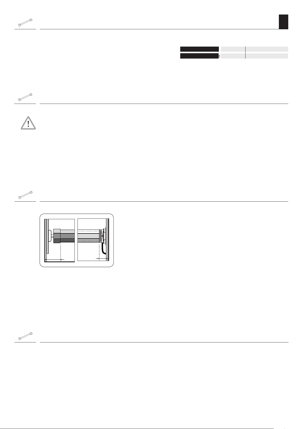
Determine the length of the rotating union (Figure )
1.
2.
3.
B = Counter bearing / Bearing capsule
C = Drive end bearing / motor
Measure the wall gap of the drive bearing (13) and counter bearing
(1) as shown.
Measure the roller shutter box and calculate the required shaft length
(L).
Length of the rotating union: L = A - (B + C)
Shorten the rotating union (5) to the required size.
Cut the shaft to size with a hacksaw at a right-angle. Remove the burrs from the shaft
internally and externally with a file.
Mounting / dismounting the adapter (Figure )
1. Mounting the adapter (10)
Slide the adapter (10) over the limit ring (18) on the drive head until
it engages. In doing so, check the correct positioning of the groove in
the adapter (10).
2. Dismantling the adapter (10)
Press the two retaining springs on the limit ring (18) downwards and
pull the adapter (10) off of the limit ring (18).
37
 Loading...