

Page 1
Installation Instructions Model 4500 Alcohol Conversion Kit
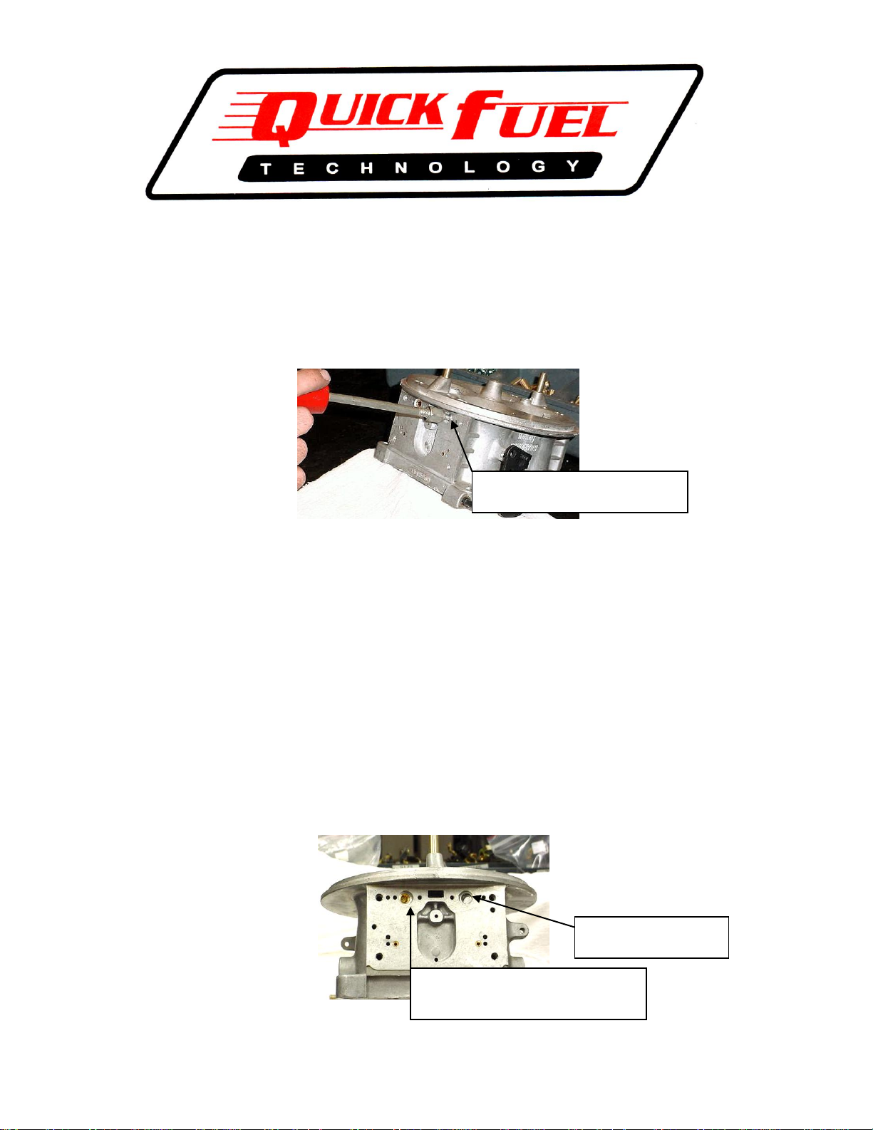
Remove booster pin with dent puller
(sheet metal screw)
Align brass pin with hole in booster, coat
with Loctite®, tap lightly, check alignment
drive until flush with casting recess.
Check alignment before
installing brass pin
Thank you for purchasing QFT’s alcohol conversion kit. This conversion is not particularly difficult
however. there are a few precautions and special instructions you should follow to be certain the conversion
goes smoothly.
1. Completely disassemble the major components; i.e. fuel bowls and metering blocks.
2. With the bowls and blocks removed, remove the locator pins that hold in the booster venturi. The
easiest way to accomplish this is to use a sheet metal screw and a dent remover as shown here.
3. With the booster venturi removed you can now install the new booster assemblies. This is a critical
step and essential that the fit and location of the booster venturi is correct. The casting that holds the
annular insert has a raised line on each side of the locator tab. This is to ensure a tight fit in the main
body casting.
4. Trial fit the booster in the main body to ensure it can be placed deep enough to align with the booster
pin hole in the main body. Look through the booster pin hole on the metering block surface of the
main body, trial fit each booster assembly to check alignment of the booster pin holes. If the holes do
not align it will be necessary to remove material from the raised casting line to achieve a tight fit,
however to enable proper alignment. Material can be removed using a hand file.
5. Once boosters are properly aligned, place a drop of two of Red Loctite® on the booster pin provided.
Insert the booster pin through the main body and into the booster. Lightly tap initially in place with a
small hammer, using a punch with the same OD as the booster pin. Check your progress frequently to
be certain the alignment is maintained. NOTE: When the last step of the booster pin enters the main
body boss the resistance to drive in the pin will become greater. Check the alignment one additional
time then finish driving the booster pin until the pin is flush with the relief cut in the main body.
6. Remove all of the air bleeds from the top section of the main body. Each throttle bore has three
threaded bleed bosses. Working from the outside, in the boss furthest away from the center of the
Page 2
carburetor install the BLANK bleed. In the boss right next to it, moving toward the center, install the
Install blank air bleed here
Install #40 here
this is the idle
air bleed.
Insert #25 bleed here, this is
the high speed bleed.
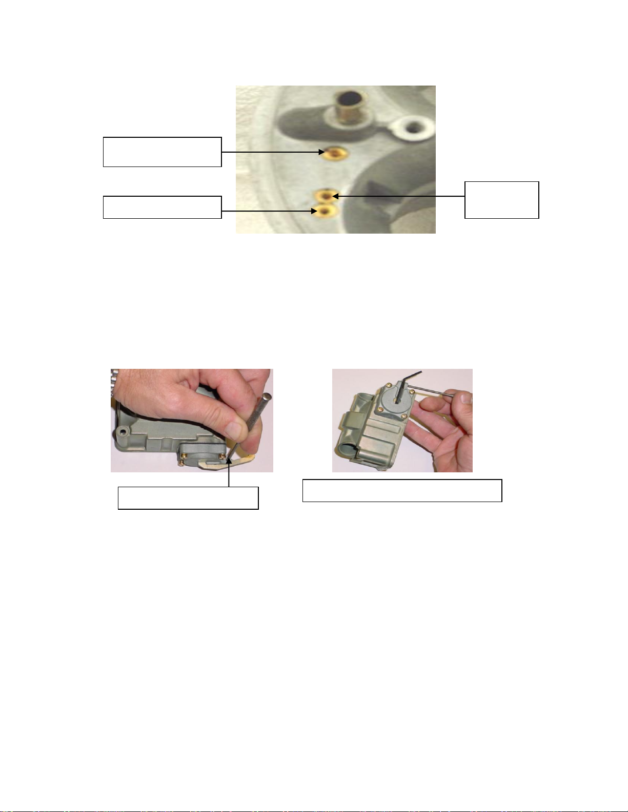
Remove roll pin with small punch
Reinstall roll pin with new pump arm as shown.
air bleed marked with the number 40. In the boss next to the accelerator pump discharge nozzle insert
the air bleed marked with the number 25. Repeat this same sequence in the remaining throttle bores.
7. Remove the two pump discharge nozzles (squirters) and stainless screws. In the small parts bag find
the two thick composite gaskets, two thin paper gaskets. Place the composite gasket on the accelerator
pump nozzle hole in the main body, slip the paper gasket over the nozzle screw, then the nozzle
(squirter) and install as a unit on top of the composite gasket, center on the locator tab and tighten with
an 5/32” Allen wrench. The main body portion is now complete
8. Place the fuel bowl so the opening is facing down on your workbench. With a small punch drive the
roll pin that retains the operating arm out of the accelerator pump housing. Install the bent pump arm
supplied with the angled section facing away or pointing down. Tap in the original roll pin with a
small punch until the roll pin is just about flush with the housing. Repeat the process on the second
bowl.
9. While the fuel bowl is still facing down on the workbench remove the old needle and seat assembly.
Hold the adjustment nut with a 5/8” wrench, with a large blade screwdriver loosen the lock screw
while holding the nut. Remove the needle and seat assembly. Set this assembly aside temporarily.
10. Turn the fuel bowl over. With a medium common tip screwdriver, remove the two screws holding in
the float assembly. Remove the entire assembly. Do both fuel bowls at the same time.
11. Lay both floats down on the workbench the same way it came out of the float bowl, with the hinge on
top. Remove the float hinge by pulling it through both the float bracket, float hinge and spring.
12. Reassemble using the new float. Place the float on the workbench in the same orientation as the bowl,
place the hinge on top of the float, and align the holes. Place the small end of the spring in the float
hinge locator hole. Slide the float hinge through the bracket and hinge holes as well as the float spring.
Once all the way through the assembly take the long end of the spring and position it in the cutout in
the float hinge. Use the other float assembly as a guide if needed. Repeat, using the first assembly as a
reference if needed.
13. Install the float assembly into each bowl. Insert the original screws and tighten. Note; these are self-
tapping screws so do not over-tighten.
14. Remove the adjusting nut and lock screw from the needle and seat assemblies. Locate the appropriate
gaskets in the small parts bag. Thread in the new needle and seat assembly into the fuel bow. When
the resistance makes it difficult, turn the fuel bowl upside down, place the large gasket on top of the
adjusting nut, slip the gasket and nut over the notch in the needle and seat assembly. Turn the nut
clockwise until the straight edge of the float is even with the center of the float bracket retainer screws.
With the float bowl still inverted, use a 3/8” drill bit, adjust the needle and seat until the drill just fits
Page 3

between the flat surface of the float and surface directly below. This is the correct dry setting and you
should not have to alter this initial setting a great deal when running. Repeat this process with the
second bowl.
15. Install the jets supplied in the metering blocks; install the power valve plug and gaskets.
16. Install the metering block gasket and fuel bowl gasket on the metering blocks.
17. Install the second fuel bowl gasket on the fuel bowl extension. Note the location of the accelerator
pump discharge hole to be certain the fuel bowl extension is properly oriented.
18. Place the metering block on the main body, install the fuel bowl extension, then install the fuel bowl
(be sure the accelerator pump operating arm is oriented correctly over the fuel bowl pump arm). Install
the blue nylon gaskets over the new, longer fuel bowl screws and insert through the fuel bowl, fuel
bowl extension and metering block. Tighten in sequence and torque to 35 inch pounds.
19. It may be necessary to re-adjust the accelerator pump orientation and over-ride spring adjustment.
With the carburetor inverted, check the alignment of the fuel bowl accelerator pump arm to be sure it is
centered on the adjustment bolt head. If necessary re-align with an adjustable wrench or suitable pliers
that will not mare the finish. Once aligned, check the pump override adjustment. There should be
tension on the fuel bowl pump arm at idle and some clearance at wide-open throttle. The
recommended clearance at wide open is .015”. The clearance does not have to be exact; the primary
reason for this measurement is to prevent the pump arm from bottoming out against the bowl. This
could possibly result in the accelerator pump housing loosening up over time resulting in a fuel leak.
20. Adjust the idle mixture screws to 2 turns from lightly seated as your baseline. You can leave your idle
speed screws in approximately the same position although this would be a good time to be certain that
your primary and secondary idle speed screws are an equal number of turns open. This helps to
balance the carburetor.
21. Install your carburetor on the intake manifold. Run your electric pump for approximately 15 seconds.
If you have a belt or engine driven mechanical pump crank the engine for approximately 15 seconds.
Operate the throttle by hand or have a helper observe that fuel is coming out the accelerator pump (this
may take a couple of strokes to fill the passage). Once you have accelerator pump shot from both the
primary and secondary you can now start the engine.
22. Note in extremely cold air temperatures or if the mixture happens to be too rich, it may be necessary to
“prime” the engine with either gasoline or in some cases carburetor cleaner will work. It does not
require a large volume just enough to give the engine a shot of a more combustible mixture.
23. Once the engine has started allow it to run at a slightly elevated speed to build a little heat in the
engine. This is a good time to check the float level to make sure they are correct. If the carburetor is
flooding or you have to adjust it down a great deal your fuel pressure is too high. The larger needle
and seat (.150” versus the standard .110”) is more difficult to close with elevated fuel pressure. If you
have to adjust the needle and seat assembly down (clockwise) then you are reducing the amount of
float drop. This will ultimately reduce the flow ability of the needle, regardless of pressure. A
properly set float level (the 3/8” dry setting you did earlier on the float bowl) will flow more at 6 P.S.I.
than a larger needle and seat adjusted down only .075” will flow at 9 P.S.I. The higher fuel pressure
will not “force” the needle to flow more. Do not confuse pressure with volume. Just because you have
pressure does automatically mean you have volume. Lower your fuel pressure and concentrate on
volume delivery. Your carburetor will work a whole lot better at low speed and you won’t have to
worry about “running out of fuel” at the top end.
24. Once the float level has been established and the engine has run long enough to build some heat, adjust
the idle mixture screws the same way you would a gasoline engine. It is necessary to find the “lean”
position of the idle mixture screws, the point at which the engine begins to slow down or labor because
it is too lean. If you turn the mixture screws in and the engine speed picks up then the mixture is too
rich. Should all the mixture screws be turned in all the way and the engine speed does not fall off then
it may be necessary to either change the idle feed restriction (reduce the size) or increase the size of the
idle air bleed (larger number). Ultimately you want to have the mixture lean out before the mixture
screw is seated, then back it out approximately ¼ turn. This gives you the best idle air/fuel mixture
setting and quality.
25. You may also want to consider installing a “lean out” valve in your intake manifold. This is simply a
device that induces a vacuum leak. The helps the engine heat up quicker when first started.
26. Once you have the float level and idle mixture settings established you can now make wide open
throttle runs. While there are numerous ways to determine the proper jetting a couple of basic
parameters help establish if you are in the correct range. First, the engine should gain a little heat
going down track, something on the order of 20 to 30 degree engine temperature. Second, you can
change jets using the MPH as a reference. If the MPH picks up you are obviously heading in the right
direction. Conversely if the MPH declines then the last change hurt the performance and probably in
the wrong direction.
Page 4

27. Alcohol is not effected as much by air temperature and/or atmospheric conditions. Therefore the
performance should be more consistent and predictable during a day of racing. The general rule of
thumb is every 40 degrees represents a 4% change in air/fuel. Normally this would be one jet number
in a gasoline jet, however, with alcohol a 4% change is going to be a wider spread, as the hole in the
main jet is so much larger. With a baseline jet of 188 a 4% increase is to a #192 a 4% decrease is to
#184.
28. We hope you enjoy your alcohol conversion kit. We remind you that alcohol, as a racing fuel is a high
maintenance product. It is not stable over a long period of time, it will absorb water from the air to the
point of equaling its own weight in water. It is our recommendation to mix your own top lube and
scent rather than purchase your fuel with these elements pre-mixed. Methanol is petroleum based
product and can transform into paraffin when it becomes unstable or with the use of mixing products
that accelerate a breakdown over a short period of time. If performance begins to fall off or flooding
begins, disassemble the fuel bowl to check for dirt, debris or paraffin.
Thank you for purchasing a Quick Fuel Technology alcohol conversion kit we are confident you will be
extremely happy with the performance. This confidence is based on the high quality; race proven
components used in this kit.
P/N 99-6
Quick Fuel Technology© 2004
 Loading...