

Page 1

V
GSM/GPRS/GPS Tracker G
User Manual
TRACGV100UM001
Revision: 1.00
100
Quectel Wireless Solutions
www.quectel.com
Info@quectel.com
Page 2

GV100 User manual
Document Title
Version
Date
Status
Document Control ID
GV100 User manual
1.00
2009-10-15
Initial
TRACGV100UM001
General Notes
Quectel offers this information as a service to its customers, to support application and
engineering efforts that use the products designed by Quectel. The information provided is
based upon requirements specifically provided to Quectel by the customers. Quectel has not
undertaken any independent search for additional relevant information, including any
information that may be in the customer’s possession. Furthermore, system validation of this
product designed by Quectel within a larger electronic system remains the responsibility of
the customer or the customer’s system integrator. All specifications supplied herein are
subject to change.
Copyright
This document contains proprietary technical information which is the property of Quectel
Limited., copying of this document and giving it to others and the using or communication of
the contents thereof, are forbidden without express authority. Offenders are liable to the
payment of damages. All rights reserved in the event of grant of a patent or the registration of
a utility model or design. All specification supplied herein are subject to change without
notice at any time.
Copyright © Shanghai Quectel Wireless Solutions Co., Ltd. 2009
TRACGv100UM001 - 1 -
Page 3

GV100 User manual
Contents
Contents ............................................................................................................................................2
0. Revision history............................................................................................................................3
1. Introduction...................................................................................................................................4
1.1. Reference.............................................................................................................................4
1.2. Terms and abbreviations......................................................................................................4
2. Product Overview .........................................................................................................................5
2.1. Appearance..........................................................................................................................5
2.2. Parts List..............................................................................................................................5
3. Interface Description And Installation Guide................................................................................7
3.1. SIM Card Interface..............................................................................................................7
3.2. Antenna Interface ................................................................................................................8
3.2.1. Install Antennas.................................................................................................8
3.2.2. GPS antenna specification.................................................................................8
3.2.3. GSM antenna specification...............................................................................9
3.3. Power Interface .................................................................................................................10
3.3.1. Power Interface definition...............................................................................10
3.3.2. Power connection............................................................................................11
3.3.3. Ignition Detect.................................................................................................12
3.3.4. Ignition Control...............................................................................................13
3.4. I/O Interface ......................................................................................................................14
3.4.1. Electrical conditions for digital inputs............................................................15
3.4.2. Digital Input without Interrupt........................................................................16
3.4.3. Digital Input with Interrupt.............................................................................16
3.4.4. Analog Input....................................................................................................16
3.4.5. Digital Output..................................................................................................17
3.4.6. Digital Output with Built-in Relay..................................................................18
3.5. Audio Interface..................................................................................................................19
3.6. RS232 Interface.................................................................................................................21
3.7. Fasten The Device.............................................................................................................22
TRACGv100UM001 - 2 -
Page 4

GV100 User manual
0. Revision history
Revision Date Author Description of change
1.00 2009-10-15 Edwin Peng Initial
TRACGv100UM001 - 3 -
Page 5
GV100 User manual
1. Introduction
The GV100 is a powerful GPS Locator designed for vehicle tracking or asserts tracking. With
superior receiving sensitivity, fast TTFF (Time to First Fix) and Quad-Band GSM frequencies
850/900/1800/1900, its location can be monitored in real time or periodically tracked by a
backend server or other specified terminals. The GV100 has multiple input/output interfaces
which can be used for monitoring or controlling external devices. Based on the integrated
@Track protocol, the GV100 can communicate with a backend server through the
GPRS/GSM network to transfer reports of Emergency, Geo-fence boundary crossings, Lower
Battery or scheduled GPS position along with many other useful functions. Users can also use
GV100 to monitor the status of a vehicle and control the vehicle with its onboard relay output.
System Integrators can easily setup their tracking systems based on the full-featured @Track
protocol.
1.1. Reference
SN Document name Remark
[1] GV100 @Track Air Interface Protocol v1 00.PDF The air protocol interface between
GV100 and backend server.
[2]
1.2. Terms and abbreviations
Abbreviation Description
TRACGv100UM001 - 4 -
Page 6
GV100 User manual
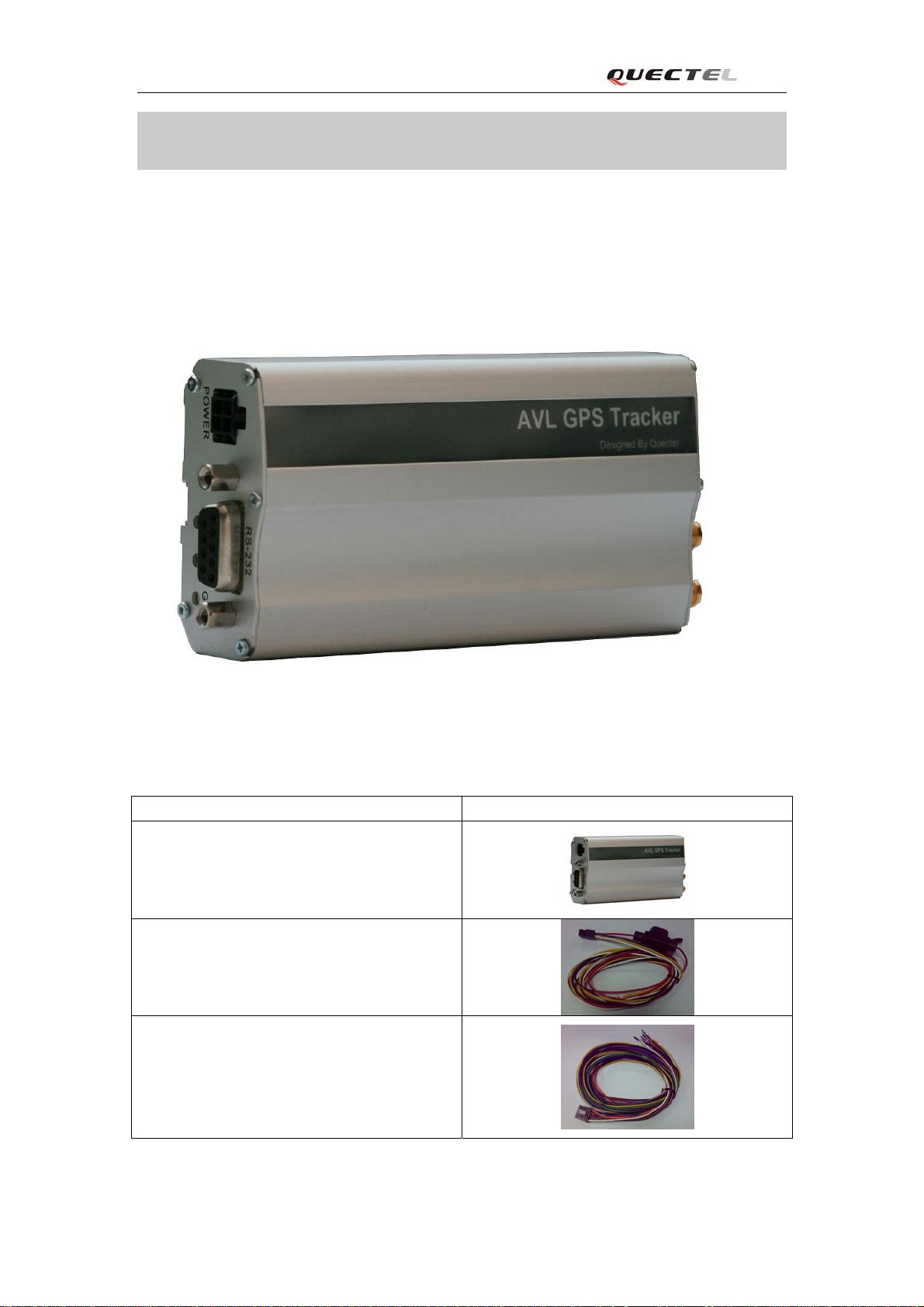
2. Product Overview
2.1. Appearance
2.2. Parts List
Name Picture
GV100 Locater
Power Cable with fuse
I/O cable
TRACGv100UM001 - 5 -
Page 7
GV100 User manual
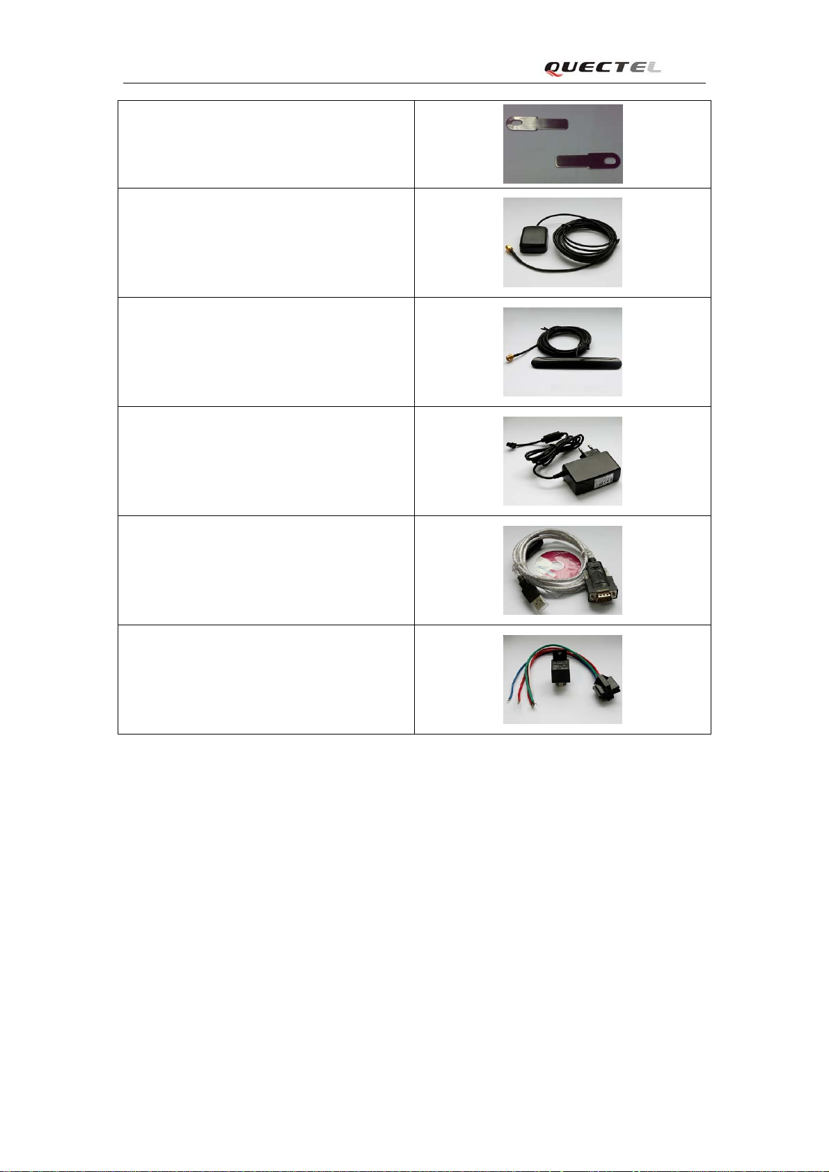
Steel Piece
GPS Antenna
GSM Antenna
12V DC power supply (Optional)
USB-232 data cable (Optional)
Relay (Optional)
TRACGv100UM001 - 6 -
Page 8
GV100 User manual
3. Interface Description And Installation Guide
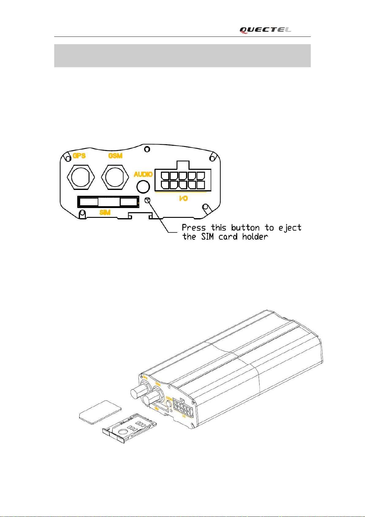
3.1. SIM Card Interface
To install the SIM card
Step 1: Press the yellow button on the right side of SIM card slot to eject the SIM card
holder.
Step 2: Put the SIM card on the SIM card holder.
Step 3: Install the SIM card holder to SIM card slot.
TRACGv100UM001 - 7 -
Page 9

GV100 User manual
3.2. Antenna Interface
3.2.1. Install Antennas
There are two SMA antenna connectors on GV100, one for GPS and another for GSM. Please
find the GSM antenna and GSM antenna in package box. Install them to the correct SMA
connector like following.
3.2.2. GPS antenna specification
GPS antenna: Frequency: 1575.42MHz
Bandwidth: >5MHz
Beamwidth: >120 deg
Supply voltage: 3.3V
Polarization: RHCP or Linear
Gain: Passive: 0dBi minimum
Active: 15dB
Impedance: 50Ω
VSWR: ﹤2
Noise figure: <3
TRACGv100UM001 - 8 -
Page 10
GV100 User manual
3.2.3. GSM antenna specification
Frequency and bandwidth
GSM850: 824MHz to 894MHz;
EGSM900: 880MHz to 960MHz;
DCS1800: 1710MHz to 1885MHz;
PCS1900: 1850MHz to 1990MHz;
Direction: Omnidirection;
Gain: Passive: >0dBi;
Impedance: 50Ω;
VSWR: <4;
Efficient:
GSM850: >40%;
EGSM900: >40%;
DCS1800: >30%;
PCS1900: >30%;
TRACGv100UM001 - 9 -
Page 11

GV100 User manual
3.3. Power Interface
3.3.1. Power Interface definition
There are four Pins on power connector:
Index Color of power cable Description Recommended Function
1 Red Power (+8V ~ 32V) Power
2 Black Ground Ground
3 Yellow Input 1 (Digital , Positive Trigger) Ignition Key Detect
4 White Digital Output 1 (Negative Trigger)
TRACGv100UM001 - 10 -
Page 12

GV100 User manual
3.3.2. Power connection
The input voltage range of GV100 is 8V to 32V DC and can be connected to vehicle’s battery
directly (12V or 24V DC). Please install the power like following.
TRACGv100UM001 - 11 -
Page 13

GV100 User manual
3.3.3. Ignition Detect
The PIN 3 of power connector is Input 1 (Digital, Positive trigger). Its electrical conditions are:
Logical State Electrical State
Active 5.0V to 32V
Inactive 0V to 3V or Open
It is strongly recommended to connect this pin to ignition key to support the power saving
function when the vehicle is off. Please note input 1 does not have interrupt and the
recommended sample rate is 3 seconds.
TRACGv100UM001 - 12 -
Page 14
GV100 User manual
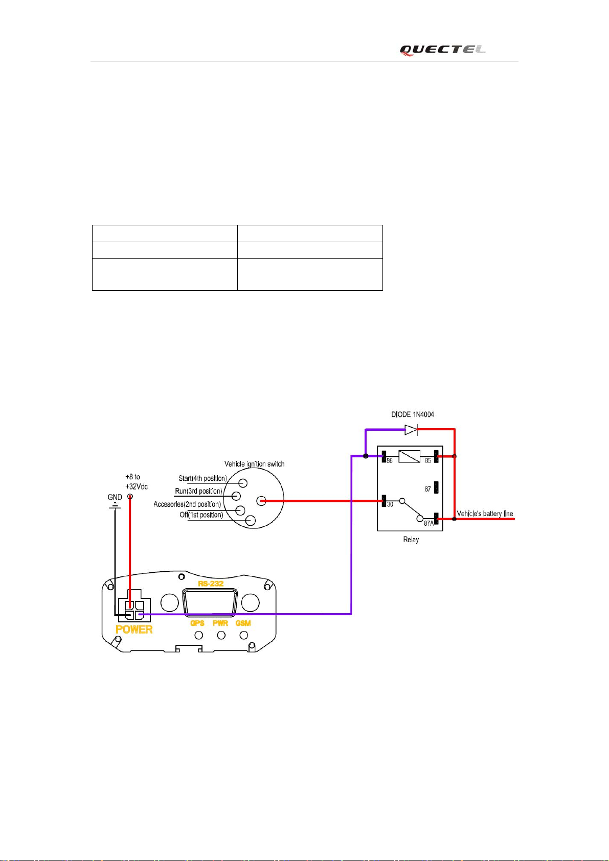
3.3.4. Ignition Control
The PIN 4 of power connector is Output 1 (Digital, Negative trigger). It is Open-Drain type
with no internal pull-up resistor which also be used to control a relay. It means that the user
has to provide a pull-up resistor or a relay coil to any positive voltage (32V max.) to detect an
inactive output by voltage. It can drive a continuous current of 0.2A.
The electrical conditions of it are:
Logical State Electrical State
Active <1.5V, max current is 0.2A
Inactive Open or the pull-up voltage
(max 32V)
User can use this pin to control a relay output. An example to control the ignition key is
showed in following figure. Please refer to chapter 3.4.5 for the detail information on how to
drive a relay with digital output.
TRACGv100UM001 - 13 -
Page 15

GV100 User manual
3.4. I/O Interface
There are several inputs and outputs on I/O cable and the definition are:
Index Color on I/O cable Description Recommended Function
1 White Input 2 (Digital , Positive Trigger)
2 Black Input 3 (Digital , Positive Trigger, With interrupt)
3 Brown Input 4 (Digital , Negative Trigger, With interrupt) Panic Button
4 Yellow Input 5 (Digital , Negative Trigger)
5 Gray Input 6 (Analog, Input voltage range : 0 – 28 V)
6 Purple Digital Output 2 (Negative Trigger)
7 Red Digital Output 3 (Negative Trigger)
8 Green Digital Output 4 (Negative Trigger)
9 Orange
10 Blue Digital Output 5 (Built in Relay)
TRACGv100UM001 - 14 -
Page 16

GV100 User manual
3.4.1. Electrical conditions for digital inputs
For negative trigger inputs the electrical conditions are:
Logical State Electrical State
Active 0V to 0.8V
Inactive 1.7V to 32V or Open
For positive trigger inputs the electrical conditions are:
Logical State Electrical State
Active 5.0V to 32V
Inactive 0V to 3V or Open
The example connections are showed in following figure:
Example connection for Positive Trigger digital inputs
Example connection for Negative Trigger digital inputs
TRACGv100UM001 - 15 -
Page 17

GV100 User manual
3.4.2. Digital Input without Interrupt
Input 2 and input 5 are digital inputs which do not have interrupt. The sample rate for these
two digital inputs is 100ms to 25 seconds. The recommend sample rate is 3 seconds. Please
note the high sample rate will also result in high power consumption. Input 2 is positive
trigger and Input 5 is negative trigger.
3.4.3. Digital Input with Interrupt
Input 3 and input 4 are digital inputs which have interrupt. Input 3 is positive trigger and input 4 is
negative trigger.
The example connections are same as showed in chapter 3.4.1.
Input 4 is also recommended to support panic button function and the connection is showed as
following.
3.4.4. Analog Input
The pin 5 of I/O cable is used for analog to digital converter. The input voltage range is 0V to
28V and can tolerant 32V voltage. Please note it is an average value based on the sample rate
of 10 seconds, which means the bust on voltage input will not be detected.
TRACGv100UM001 - 16 -
Page 18

GV100 User manual
3.4.5. Digital Output
The outputs are Open-Drain type with no internal pull-up resistor which also be used to
control a relay. It means that the user has to provide a pull-up resistor or a relay coil to any
positive voltage (32V max.) to detect an inactive output by voltage. Each output can drive a
continuous current of 0.2A.
The electrical conditions are:
Logical State Electrical State
Active <1.5V, max current is 0.2A
Inactive Open or the pull-up voltage
(max 32V)
The outputs are used for cutting/restoring GND. The example connections are:
The example connection to drive a LED
The example connection to drive a Relay
If the digital output is used to drive a relay, a catch diode is showed across the relay coil, this
is necessary to prevent damage to the digital output when the relay is turned off. Many
modern relays come with this diode pre-installed internal to the relay itself. If the relay has
this diode, insure the proper relay polarity connected is used. If this diode is not internal, it
should be added externally. A common diode such as a 1N4004 will work in most
circumstances.
TRACGv100UM001 - 17 -
Page 19

GV100 User manual
3.4.6. Digital Output with Built-in Relay
The build in relay output is Open-Drain type with no internal pull-up resistor. It means that
the user has to provide a pull-up resistor to any positive voltage to detect an inactive output by
voltage. The switch capacity of the relay contact is 60W, so it can drive a continuous current
of 2A at the input voltage of 30V and 1.85A at the input voltage of 32V.
The electrical conditions are:
Logical State Electrical State
Active 0V
Inactive Open or the pull-up voltage
(max 32V)
The output is used for cutting/restoring GND. It can be directly drive a LED and the example
connection is showed as following.
TRACGv100UM001 - 18 -
Page 20

GV100 User manual
3.5. Audio Interface
The audio connector is designed to connect a non-balanced hands-free audio system. It is
designed to use a 2.5mm stereo plug with the following configuration, please pay attention to
the common GND ,this common GND is used only for audio ground, it should not used as a
power ground. The speaker interface can be connected to a 32ohm speaker or an audio
amplifier which drive a louder speaker. The electret microphone is recommended.
Audio Jack Interface Definition
Example connection for audio
TRACGv100UM001 - 19 -
Page 21

GV100 User manual
Microphone input characteristics
Parameter
Working Voltage
Working Current
External
Min Typ Max Unit
1.0 1.5 2.0 V
200 500
2.2
uA
k Ohm
Microphone Load
Resistance
Speaker output characteristics
Parameter Min Typ Max Unit
Speaker load
Resistance
Speaker output
level
Maxim driving
16 32
0 2.4
50
Ohm
Vpp
mA
current limit of
speaker
TRACGv100UM001 - 20 -
Page 22

GV100 User manual
3.6. RS232 Interface
An RS232 interface has been implemented on GV100 and it can be used to configure the runtime
parameters of GV100.
RS232 DB-9 Connector Pin Description (PC side)
Pin Index Signal Name Signal Description
1 CD Carrier Detect
2 RXD Receive Data
3 TXD Transmit Data
4 DTR Data Terminal Ready
5 GND Ground
6 None None
7 RTS Request To Send
8 CTS Clear To Send
9 RI Ring Indicator
TRACGv100UM001 - 21 -
Page 23

GV100 User manual
3.7. Fasten The Device
Please use the steel piece and screw to fasten the device.
TRACGv100UM001 - 22 -
Page 24

GV100 User manual
4. Compliance
This transmitter is using outdoor antennas that operate at 20cm or more from nearby persons.
TRACGv100UM001 - 23 -
Page 25

GV100 User manual
TRACGv100UM001 - 24 -
Page 26

Shanghai Quectel Wireless Solutions Co., Ltd.
Room 801, Building E, No.1618, Yishan Road, Shanghai, China 201103
Tel: +86 21 5108 2965
Mail:
info@quectel.com
 Loading...