

Page 1

Scalar 1000 Library
Operator Guide
Page 2

Copyright Notice
© 2002–2004 ADIC
The information contained in this document is subject to change without notice.
This document contains proprietary information which is protected by copyright. All rights are
reserved. No part of this document may be photocopied, reproduced, or translated to another
language without prior written consent of ADIC.
ADIC shall not be liable for errors contained herein or for incidental or consequential damages
(including lost profits) in connection with the furnishing, performance or use of this material
whether based on warranty, contract, or other legal theory.
All trademarks are the property of their respective owners.
Copyright Notice (Europe)
© 2002–2004 ADIC Europe™
All rights reserved. No part of this document may be copied or reproduced in any form or by any
means, without prior written permission of ADIC Europe, ZAC des Basses Auges, 1,rue Alfred de
Vigny, 78112 - Fourqueux, France.
ADIC Europe assumes no responsibility for any errors that may appear in this document, and
retains the right to make changes to these specifications and descriptions at any time, without
notice.
This publication may describe designs for which patents are pending, or have been granted. By
publishing this information, ADIC Europe conveys no license under any patent or any other right.
ADIC Europe makes no representation or warranty with respect to the contents of this document
and specifically disclaims any implied warranties of merchantability or fitness for any particular
purpose. Further, ADIC Europe reserves the right to revise or change this publication without
obligation on the part of ADIC Europe to notify any person or organization of such revision of
change.
Every effort has been made to acknowledge trademarks and their owners. Trad emarked names are
used solely for identification or exemplary purposes, any omission is unintentional.
ADIC is a registered trademark and ADIC Europe is a trademark of Advanced Digital Information
Corporation.
ADIC USA
Tel.: +1-303-705-3900
Fax: +1-303-792-2465
ATAC: 1-800-827-3822
www.adic.com
Document number: 6-00054-02 Rev A
Published: 22 June 2004 Printed in the USA
ADIC Europe
ZAC des Basses Auges
1, rue Alfred de Vigny
78112 Fourqueux, France
Tel.: +33.1.3087.5300
Fax: +33.1.3087.5301
ADIC Germany Beteiligungs GmbH, KG
Eschenstraße 3
D-89558
Böhmenkirch, Germany
Tel: +00.800.9999.3822
ADIC CORPORATE • 11431 WILLOWS ROAD, NE • REDMOND, WASHINGTON , USA • 1-800-33 6-1233
ADIC • 8560 UPLAND DRIVE• ENGLEWOOD, COLORADO, USA • 1-800-827-3822
ADIC • 10 BROWN ROAD • ITHACA, NEW YORK, USA • 1-607-241-4800
Page 3

Contents
1
About this Guide
Overview . . . . . . . . . . . . . . . . . . . . . . . . . . . . . . . . . . . . . . . . . . . . . . . . . . . . . . . . . . . . . . .1-3
Intended Audience . . . . . . . . . . . . . . . . . . . . . . . . . . . . . . . . . . . . . . . . . . . . . . . . . . . . . . .1-3
Organization . . . . . . . . . . . . . . . . . . . . . . . . . . . . . . . . . . . . . . . . . . . . . . . . . . . . . . . . . . . .1-3
Associated Documents . . . . . . . . . . . . . . . . . . . . . . . . . . . . . . . . . . . . . . . . . . . . . . . . . . . .1-4
Explanation of Symbols and Notes . . . . . . . . . . . . . . . . . . . . . . . . . . . . . . . . . . . . . . . . . .1-4
ADIC Technical Assistance Center . . . . . . . . . . . . . . . . . . . . . . . . . . . . . . . . . . . . . . . . . .1-5
Regulatory Notices . . . . . . . . . . . . . . . . . . . . . . . . . . . . . . . . . . . . . . . . . . . . . . . . . . . . . . .1-6
Federal Communication Commission Class A Notice . . . . . . . . . . . . . . . . . . . . . .1-6
IC Notice (Canada Only) . . . . . . . . . . . . . . . . . . . . . . . . . . . . . . . . . . . . . . . . . . . . . . .1-7
EN 55022 Compliance (Czech Republic Only) . . . . . . . . . . . . . . . . . . . . . . . . . . . .1-8
CE Notice . . . . . . . . . . . . . . . . . . . . . . . . . . . . . . . . . . . . . . . . . . . . . . . . . . . . . . . . . . . .1-8
VCCI Notices (Japan Only) . . . . . . . . . . . . . . . . . . . . . . . . . . . . . . . . . . . . . . . . . . . .1-10
Declaration of Conformity . . . . . . . . . . . . . . . . . . . . . . . . . . . . . . . . . . . . . . . . . . . .1-10
iii
Page 4

2
System Description
General Description . . . . . . . . . . . . . . . . . . . . . . . . . . . . . . . . . . . . . . . . . . . . . . . . . . . . . .2-3
Modules . . . . . . . . . . . . . . . . . . . . . . . . . . . . . . . . . . . . . . . . . . . . . . . . . . . . . . . . . . . . . . . .2-5
Control Module . . . . . . . . . . . . . . . . . . . . . . . . . . . . . . . . . . . . . . . . . . . . . . . . . . . . . .2-6
Expansion Module . . . . . . . . . . . . . . . . . . . . . . . . . . . . . . . . . . . . . . . . . . . . . . . . . . . .2-6
Internal Components . . . . . . . . . . . . . . . . . . . . . . . . . . . . . . . . . . . . . . . . . . . . . . . . . . . . .2-7
Tape Drives . . . . . . . . . . . . . . . . . . . . . . . . . . . . . . . . . . . . . . . . . . . . . . . . . . . . . . . . . .2-7
Cartridge Storage . . . . . . . . . . . . . . . . . . . . . . . . . . . . . . . . . . . . . . . . . . . . . . . . . . . . .2-8
Cartridge Accessor . . . . . . . . . . . . . . . . . . . . . . . . . . . . . . . . . . . . . . . . . . . . . . . . . . .2-12
Tape Cartridges . . . . . . . . . . . . . . . . . . . . . . . . . . . . . . . . . . . . . . . . . . . . . . . . . . . . .2-13
Insert/Eject Station . . . . . . . . . . . . . . . . . . . . . . . . . . . . . . . . . . . . . . . . . . . . . . . . . .2-14
Connectivity . . . . . . . . . . . . . . . . . . . . . . . . . . . . . . . . . . . . . . . . . . . . . . . . . . . . . . . . . . . .2-14
SAN Connectivity . . . . . . . . . . . . . . . . . . . . . . . . . . . . . . . . . . . . . . . . . . . . . . . . . . .2-14
SCSI Connectivity . . . . . . . . . . . . . . . . . . . . . . . . . . . . . . . . . . . . . . . . . . . . . . . . . . .2-16
Scalar DLC Option . . . . . . . . . . . . . . . . . . . . . . . . . . . . . . . . . . . . . . . . . . . . . . . . . . . . . .2-17
Remote Management Unit . . . . . . . . . . . . . . . . . . . . . . . . . . . . . . . . . . . . . . . . . . . . . . . .2-18
3
Safety
Overview . . . . . . . . . . . . . . . . . . . . . . . . . . . . . . . . . . . . . . . . . . . . . . . . . . . . . . . . . . . . . . .3-3
Intended Use . . . . . . . . . . . . . . . . . . . . . . . . . . . . . . . . . . . . . . . . . . . . . . . . . . . . . . . . . . . .3-3
Hazard Alert Messages . . . . . . . . . . . . . . . . . . . . . . . . . . . . . . . . . . . . . . . . . . . . . . . . . . . .3-3
Area of Application . . . . . . . . . . . . . . . . . . . . . . . . . . . . . . . . . . . . . . . . . . . . . . . . . . . . . . .3-5
Protective Devices . . . . . . . . . . . . . . . . . . . . . . . . . . . . . . . . . . . . . . . . . . . . . . . . . . . . . . . .3-5
Library Access . . . . . . . . . . . . . . . . . . . . . . . . . . . . . . . . . . . . . . . . . . . . . . . . . . . . . . .3-5
Mechanical Lock . . . . . . . . . . . . . . . . . . . . . . . . . . . . . . . . . . . . . . . . . . . . . . . . . .3-6
Main Circuit Breaker (Power) Switch . . . . . . . . . . . . . . . . . . . . . . . . . . . . . . . . . . . .3-6
iv Contents
6-00054-02 Rev A
Page 5

4
Operation
Overview . . . . . . . . . . . . . . . . . . . . . . . . . . . . . . . . . . . . . . . . . . . . . . . . . . . . . . . . . . . . . . .4-3
Using the Operator Panel . . . . . . . . . . . . . . . . . . . . . . . . . . . . . . . . . . . . . . . . . . . . . . . . . .4-3
Starting the Scalar 1000 . . . . . . . . . . . . . . . . . . . . . . . . . . . . . . . . . . . . . . . . . . . . . . . . . . . .4-7
Shutting Down the Scalar 1000 . . . . . . . . . . . . . . . . . . . . . . . . . . . . . . . . . . . . . . . . . . . . .4-9
Normal Shutdown . . . . . . . . . . . . . . . . . . . . . . . . . . . . . . . . . . . . . . . . . . . . . . . . . . . .4-9
Emergency Shutdown . . . . . . . . . . . . . . . . . . . . . . . . . . . . . . . . . . . . . . . . . . . . . . . .4-10
Restarting the Scalar 1000 . . . . . . . . . . . . . . . . . . . . . . . . . . . . . . . . . . . . . . . . . . . . . . . . .4-11
Using the Remote Management Unit . . . . . . . . . . . . . . . . . . . . . . . . . . . . . . . . . . . . . . .4-11
Supported Browsers . . . . . . . . . . . . . . . . . . . . . . . . . . . . . . . . . . . . . . . . . . . . . . . . .4-12
System Administrator Responsibilities . . . . . . . . . . . . . . . . . . . . . . . . . . . . . . . . . .4-12
RMU Prerequisites . . . . . . . . . . . . . . . . . . . . . . . . . . . . . . . . . . . . . . . . . . . . . . . . . . .4-12
Setting up the RMU . . . . . . . . . . . . . . . . . . . . . . . . . . . . . . . . . . . . . . . . . . . . . . . . .4-13
Accessing the RMU . . . . . . . . . . . . . . . . . . . . . . . . . . . . . . . . . . . . . . . . . . . . . . . . . .4-14
Logging into the RMU . . . . . . . . . . . . . . . . . . . . . . . . . . . . . . . . . . . . . . . . . . . . . . . .4-14
Checking Status and General Information . . . . . . . . . . . . . . . . . . . . . . . . . . . . . . .4-14
Configuring Network Parameters . . . . . . . . . . . . . . . . . . . . . . . . . . . . . . . . . . . . . .4-15
Configuring SNMP . . . . . . . . . . . . . . . . . . . . . . . . . . . . . . . . . . . . . . . . . . . . . . . . . .4-16
Downloading the SNMP MIB File . . . . . . . . . . . . . . . . . . . . . . . . . . . . . . . . . .4-17
Configuring RMU Users . . . . . . . . . . . . . . . . . . . . . . . . . . . . . . . . . . . . . . . . . . . . . .4-17
Adding/Removing Users . . . . . . . . . . . . . . . . . . . . . . . . . . . . . . . . . . . . . . . . .4-17
Changing a Password . . . . . . . . . . . . . . . . . . . . . . . . . . . . . . . . . . . . . . . . . . . . .4-18
Configuring the Time and Date . . . . . . . . . . . . . . . . . . . . . . . . . . . . . . . . . . . . . . . .4-19
Synchronizing with an NTP Server . . . . . . . . . . . . . . . . . . . . . . . . . . . . . . . . .4-19
Updating Firmware . . . . . . . . . . . . . . . . . . . . . . . . . . . . . . . . . . . . . . . . . . . . . . . . . .4-20
Viewing Diagnostic Files (Library and RMU Logs) . . . . . . . . . . . . . . . . . . . . . . .4-20
Using the Operator Panel (via the RMU) . . . . . . . . . . . . . . . . . . . . . . . . . . . . . . . .4-21
Viewing Logs . . . . . . . . . . . . . . . . . . . . . . . . . . . . . . . . . . . . . . . . . . . . . . . . . . . . . . .4-21
Getting Help . . . . . . . . . . . . . . . . . . . . . . . . . . . . . . . . . . . . . . . . . . . . . . . . . . . . . . . .4-21
22 June 2004
Contents v
Page 6

5
Menus and Commands
Overview . . . . . . . . . . . . . . . . . . . . . . . . . . . . . . . . . . . . . . . . . . . . . . . . . . . . . . . . . . . . . . .5-5
Using the Operator Panel Menu . . . . . . . . . . . . . . . . . . . . . . . . . . . . . . . . . . . . . . . . . . . .5-5
Accessing the Menu . . . . . . . . . . . . . . . . . . . . . . . . . . . . . . . . . . . . . . . . . . . . . . . . . . .5-5
Special Characters or Cursors . . . . . . . . . . . . . . . . . . . . . . . . . . . . . . . . . . . . . . . . . .5-6
Help Button . . . . . . . . . . . . . . . . . . . . . . . . . . . . . . . . . . . . . . . . . . . . . . . . . . . . . . . . . .5-8
Operator Intervention Message . . . . . . . . . . . . . . . . . . . . . . . . . . . . . . . . . . . . . . . . .5-8
Main Menu . . . . . . . . . . . . . . . . . . . . . . . . . . . . . . . . . . . . . . . . . . . . . . . . . . . . . . . . . . . . . .5-9
Mode Dialog . . . . . . . . . . . . . . . . . . . . . . . . . . . . . . . . . . . . . . . . . . . . . . . . . . . . . . . . . . . .5-10
Status Menu . . . . . . . . . . . . . . . . . . . . . . . . . . . . . . . . . . . . . . . . . . . . . . . . . . . . . . . . . . . .5-12
Library Submenu . . . . . . . . . . . . . . . . . . . . . . . . . . . . . . . . . . . . . . . . . . . . . . . . . . . .5-13
SCSI Submenu . . . . . . . . . . . . . . . . . . . . . . . . . . . . . . . . . . . . . . . . . . . . . . . . . . .5-13
Mode Parms Dialog . . . . . . . . . . . . . . . . . . . . . . . . . . . . . . . . . . . . . . . . . . .5-14
Element Address . . . . . . . . . . . . . . . . . . . . . . . . . . . . . . . . . . . . . . . . . 5-15
Mixed-Media Support. . . . . . . . . . . . . . . . . . . . . . . . . . . . . . . . . . . . . 5-15
Parity . . . . . . . . . . . . . . . . . . . . . . . . . . . . . . . . . . . . . . . . . . . . . . . . . . . 5-17
LCD . . . . . . . . . . . . . . . . . . . . . . . . . . . . . . . . . . . . . . . . . . . . . . . . . . . . 5-18
Reservations Dialog . . . . . . . . . . . . . . . . . . . . . . . . . . . . . . . . . . . . . . . . . . .5-19
System Dialog . . . . . . . . . . . . . . . . . . . . . . . . . . . . . . . . . . . . . . . . . . . . . . . . . . .5-20
Element Dialog . . . . . . . . . . . . . . . . . . . . . . . . . . . . . . . . . . . . . . . . . . . . . . . . . .5-22
Logs Submenu . . . . . . . . . . . . . . . . . . . . . . . . . . . . . . . . . . . . . . . . . . . . . . . . . . .5-26
Command Log Dialog . . . . . . . . . . . . . . . . . . . . . . . . . . . . . . . . . . . . . . . . .5-26
Error Log Dialog. . . . . . . . . . . . . . . . . . . . . . . . . . . . . . . . . . . . . . . . . . . . . .5-28
Drive Error Log Dialog . . . . . . . . . . . . . . . . . . . . . . . . . . . . . . . . . . . . . . . .5-30
Drives Submenu . . . . . . . . . . . . . . . . . . . . . . . . . . . . . . . . . . . . . . . . . . . . . . . . . . . . .5-30
Drive State Dialog . . . . . . . . . . . . . . . . . . . . . . . . . . . . . . . . . . . . . . . . . . . . . . . .5-31
Media Info Dialog . . . . . . . . . . . . . . . . . . . . . . . . . . . . . . . . . . . . . . . . . . . . . . . .5-32
vi Contents
Commands Menu . . . . . . . . . . . . . . . . . . . . . . . . . . . . . . . . . . . . . . . . . . . . . . . . . . . . . . .5-35
Park . . . . . . . . . . . . . . . . . . . . . . . . . . . . . . . . . . . . . . . . . . . . . . . . . . . . . . . . . . . . . . .5-36
Move Submenu . . . . . . . . . . . . . . . . . . . . . . . . . . . . . . . . . . . . . . . . . . . . . . . . . . . . . .5-36
Position to Elem Dialog . . . . . . . . . . . . . . . . . . . . . . . . . . . . . . . . . . . . . . . . . . .5-37
Move Media Dialog . . . . . . . . . . . . . . . . . . . . . . . . . . . . . . . . . . . . . . . . . . . . . .5-39
Inventory Dialog . . . . . . . . . . . . . . . . . . . . . . . . . . . . . . . . . . . . . . . . . . . . . . . . . . . .5-43
Insert/Eject Submenu . . . . . . . . . . . . . . . . . . . . . . . . . . . . . . . . . . . . . . . . . . . . . . . .5-45
Insert Screen . . . . . . . . . . . . . . . . . . . . . . . . . . . . . . . . . . . . . . . . . . . . . . . . . . . . .5-45
Insert Clean Tape Dialog . . . . . . . . . . . . . . . . . . . . . . . . . . . . . . . . . . . . . . . . . .5-47
Eject Dialog . . . . . . . . . . . . . . . . . . . . . . . . . . . . . . . . . . . . . . . . . . . . . . . . . . . . .5-52
Eject Clean Tape Submenu . . . . . . . . . . . . . . . . . . . . . . . . . . . . . . . . . . . . . . . .5-55
Expired Tapes . . . . . . . . . . . . . . . . . . . . . . . . . . . . . . . . . . . . . . . . . . . . . . . .5-55
6-00054-02 Rev A
Page 7

By Coordinate Dialog. . . . . . . . . . . . . . . . . . . . . . . . . . . . . . . . . . . . . . . . . .5-57
By Volser Dialog . . . . . . . . . . . . . . . . . . . . . . . . . . . . . . . . . . . . . . . . . . . . . .5-60
Database Menu . . . . . . . . . . . . . . . . . . . . . . . . . . . . . . . . . . . . . . . . . . . . . . . . . . . . . . . . .5-62
Media Dialog . . . . . . . . . . . . . . . . . . . . . . . . . . . . . . . . . . . . . . . . . . . . . . . . . . . . . . . .5-63
Element Dialog . . . . . . . . . . . . . . . . . . . . . . . . . . . . . . . . . . . . . . . . . . . . . . . . . . . . . .5-64
Config Dialog . . . . . . . . . . . . . . . . . . . . . . . . . . . . . . . . . . . . . . . . . . . . . . . . . . . . . . .5-67
Advanced Dialog . . . . . . . . . . . . . . . . . . . . . . . . . . . . . . . . . . . . . . . . . . . . . . . . . . . .5-69
Learn Dialog . . . . . . . . . . . . . . . . . . . . . . . . . . . . . . . . . . . . . . . . . . . . . . . . . . . .5-69
Manipulate Get . . . . . . . . . . . . . . . . . . . . . . . . . . . . . . . . . . . . . . . . . . . . . . . . . .5-70
Manipulate Put . . . . . . . . . . . . . . . . . . . . . . . . . . . . . . . . . . . . . . . . . . . . . . . . . .5-70
Setup Menu . . . . . . . . . . . . . . . . . . . . . . . . . . . . . . . . . . . . . . . . . . . . . . . . . . . . . . . . . . . .5- 7 1
Library Submenu . . . . . . . . . . . . . . . . . . . . . . . . . . . . . . . . . . . . . . . . . . . . . . . . . . . .5-72
SCSI Submenu . . . . . . . . . . . . . . . . . . . . . . . . . . . . . . . . . . . . . . . . . . . . . . . . . . .5-73
Target ID Dialog . . . . . . . . . . . . . . . . . . . . . . . . . . . . . . . . . . . . . . . . . . . . . .5-74
Parity Dialog . . . . . . . . . . . . . . . . . . . . . . . . . . . . . . . . . . . . . . . . . . . . . . . . .5-75
Ports Dialog . . . . . . . . . . . . . . . . . . . . . . . . . . . . . . . . . . . . . . . . . . . . . . . . . .5-76
Host Dialog . . . . . . . . . . . . . . . . . . . . . . . . . . . . . . . . . . . . . . . . . . . . . . . . . . . . .5-77
Trace Dialog . . . . . . . . . . . . . . . . . . . . . . . . . . . . . . . . . . . . . . . . . . . . . . . . . . . . .5-78
Security Dialog . . . . . . . . . . . . . . . . . . . . . . . . . . . . . . . . . . . . . . . . . . . . . . . . . .5-79
Switching Security From Off to On . . . . . . . . . . . . . . . . . . . . . . . . . . . . . .5-79
Switching Security From On to Off . . . . . . . . . . . . . . . . . . . . . . . . . . . . . .5-81
Changing the Password. . . . . . . . . . . . . . . . . . . . . . . . . . . . . . . . . . . . . . . .5-82
Media Dialog . . . . . . . . . . . . . . . . . . . . . . . . . . . . . . . . . . . . . . . . . . . . . . . . . . . .5-84
Emulate Dialog . . . . . . . . . . . . . . . . . . . . . . . . . . . . . . . . . . . . . . . . . . . . . . . . . .5-86
RMU Submenu . . . . . . . . . . . . . . . . . . . . . . . . . . . . . . . . . . . . . . . . . . . . . . . . . .5-87
Name Dialog . . . . . . . . . . . . . . . . . . . . . . . . . . . . . . . . . . . . . . . . . . . . . . . . .5-87
IP Dialog. . . . . . . . . . . . . . . . . . . . . . . . . . . . . . . . . . . . . . . . . . . . . . . . . . . . .5-88
Advanced Dialog . . . . . . . . . . . . . . . . . . . . . . . . . . . . . . . . . . . . . . . . . . . . . . . .5-89
Drives Dialog . . . . . . . . . . . . . . . . . . . . . . . . . . . . . . . . . . . . . . . . . . . . . . . . . . . . . . .5-91
Cleaning Submenu . . . . . . . . . . . . . . . . . . . . . . . . . . . . . . . . . . . . . . . . . . . . . . . . . . .5-93
Drives Dialog . . . . . . . . . . . . . . . . . . . . . . . . . . . . . . . . . . . . . . . . . . . . . . . . . . . .5-93
Media Dialog . . . . . . . . . . . . . . . . . . . . . . . . . . . . . . . . . . . . . . . . . . . . . . . . . . . .5-94
View Dialog . . . . . . . . . . . . . . . . . . . . . . . . . . . . . . . . . . . . . . . . . . . . . . . . . . . . .5-96
Utils Menu . . . . . . . . . . . . . . . . . . . . . . . . . . . . . . . . . . . . . . . . . . . . . . . . . . . . . . . . . . . . .5-97
Library Submenu . . . . . . . . . . . . . . . . . . . . . . . . . . . . . . . . . . . . . . . . . . . . . . . . . . . .5-97
Screen Dialog . . . . . . . . . . . . . . . . . . . . . . . . . . . . . . . . . . . . . . . . . . . . . . . . . . . .5-98
Audio Dialog . . . . . . . . . . . . . . . . . . . . . . . . . . . . . . . . . . . . . . . . . . . . . . . . . . .5-100
Dump . . . . . . . . . . . . . . . . . . . . . . . . . . . . . . . . . . . . . . . . . . . . . . . . . . . . . . . . .5-101
Time Dialog . . . . . . . . . . . . . . . . . . . . . . . . . . . . . . . . . . . . . . . . . . . . . . . . . . . .5-101
Date Dialog . . . . . . . . . . . . . . . . . . . . . . . . . . . . . . . . . . . . . . . . . . . . . . . . . . . .5-102
Drives Submenu . . . . . . . . . . . . . . . . . . . . . . . . . . . . . . . . . . . . . . . . . . . . . . . . . . . .5-103
Update Microcode Dialog . . . . . . . . . . . . . . . . . . . . . . . . . . . . . . . . . . . . . . . .5-104
Clean Drives Dialog . . . . . . . . . . . . . . . . . . . . . . . . . . . . . . . . . . . . . . . . . . . . .5 -108
Unload Drives Dialog . . . . . . . . . . . . . . . . . . . . . . . . . . . . . . . . . . . . . . . . . . . .5-110
Initialize Submenu . . . . . . . . . . . . . . . . . . . . . . . . . . . . . . . . . . . . . . . . . . . . . .5-111
Communication. . . . . . . . . . . . . . . . . . . . . . . . . . . . . . . . . . . . . . . . . . . . . .5-112
SCSI. . . . . . . . . . . . . . . . . . . . . . . . . . . . . . . . . . . . . . . . . . . . . . . . . . . . . . . .5-112
22 June 2004
Contents vii
Page 8

Service Menu . . . . . . . . . . . . . . . . . . . . . . . . . . . . . . . . . . . . . . . . . . . . . . . . . . . . . . . . . .5-113
Start Dialog . . . . . . . . . . . . . . . . . . . . . . . . . . . . . . . . . . . . . . . . . . . . . . . . . . . . . . . .5-114
Diags Submenu . . . . . . . . . . . . . . . . . . . . . . . . . . . . . . . . . . . . . . . . . . . . . . . . . . . . .5-116
DI/DO Submenu . . . . . . . . . . . . . . . . . . . . . . . . . . . . . . . . . . . . . . . . . . . . . . .5-117
Loopback Dialog. . . . . . . . . . . . . . . . . . . . . . . . . . . . . . . . . . . . . . . . . . . . .5-117
Sensors Submenu . . . . . . . . . . . . . . . . . . . . . . . . . . . . . . . . . . . . . . . . . . . .5-118
Wrap Dialog. . . . . . . . . . . . . . . . . . . . . . . . . . . . . . . . . . . . . . . . . . . . 5-118
Real Time . . . . . . . . . . . . . . . . . . . . . . . . . . . . . . . . . . . . . . . . . . . . . . 5-120
Locks Dialog . . . . . . . . . . . . . . . . . . . . . . . . . . . . . . . . . . . . . . . . . . . . . . . .5-121
Gripper Submenu . . . . . . . . . . . . . . . . . . . . . . . . . . . . . . . . . . . . . . . . . . . . . . .5-121
Get/Put Storage Dialog . . . . . . . . . . . . . . . . . . . . . . . . . . . . . . . . . . . . . . .5-122
Get/Put Drives Dialog. . . . . . . . . . . . . . . . . . . . . . . . . . . . . . . . . . . . . . . .5-125
Step Dialog. . . . . . . . . . . . . . . . . . . . . . . . . . . . . . . . . . . . . . . . . . . . . . . . . .5-128
Scanner Submenu . . . . . . . . . . . . . . . . . . . . . . . . . . . . . . . . . . . . . . . . . . . . . . .5-130
Adjust Dialog. . . . . . . . . . . . . . . . . . . . . . . . . . . . . . . . . . . . . . . . . . . . . . . .5-130
Trigger Dialog . . . . . . . . . . . . . . . . . . . . . . . . . . . . . . . . . . . . . . . . . . . . . . .5-131
Fiducial Test Dialog . . . . . . . . . . . . . . . . . . . . . . . . . . . . . . . . . . . . . . . . . .5-132
Accessor Submenu . . . . . . . . . . . . . . . . . . . . . . . . . . . . . . . . . . . . . . . . . . . . . .5-133
Move Dialog . . . . . . . . . . . . . . . . . . . . . . . . . . . . . . . . . . . . . . . . . . . . . . . .5-134
Step Dialog. . . . . . . . . . . . . . . . . . . . . . . . . . . . . . . . . . . . . . . . . . . . . . . . . .5-135
SelfTest Dialog . . . . . . . . . . . . . . . . . . . . . . . . . . . . . . . . . . . . . . . . . . . . . . . . . .5-136
PowerSup Dialog . . . . . . . . . . . . . . . . . . . . . . . . . . . . . . . . . . . . . . . . . . . . . . .5-137
Teach Submenu . . . . . . . . . . . . . . . . . . . . . . . . . . . . . . . . . . . . . . . . . . . . . . . . . . . .5-138
Teach New Dialog . . . . . . . . . . . . . . . . . . . . . . . . . . . . . . . . . . . . . . . . . . . . . . .5-138
Teach Current Dialog . . . . . . . . . . . . . . . . . . . . . . . . . . . . . . . . . . . . . . . . . . . .5-140
SAC Dialog . . . . . . . . . . . . . . . . . . . . . . . . . . . . . . . . . . . . . . . . . . . . . . . . . . . . . . . .5-143
Demo Dialog . . . . . . . . . . . . . . . . . . . . . . . . . . . . . . . . . . . . . . . . . . . . . . . . . . . . . . .5-143
Advanced Dialog . . . . . . . . . . . . . . . . . . . . . . . . . . . . . . . . . . . . . . . . . . . . . . . . . . .5-146
Other Dialog . . . . . . . . . . . . . . . . . . . . . . . . . . . . . . . . . . . . . . . . . . . . . . . . . . . . . . .5-147
viii Contents
About Screen . . . . . . . . . . . . . . . . . . . . . . . . . . . . . . . . . . . . . . . . . . . . . . . . . . . . . . . . . .5-148
6
Processing Media
Overview . . . . . . . . . . . . . . . . . . . . . . . . . . . . . . . . . . . . . . . . . . . . . . . . . . . . . . . . . . . . . . .6-3
Tape Cartridge Maintenance . . . . . . . . . . . . . . . . . . . . . . . . . . . . . . . . . . . . . . . . . . . . . . .6-3
Inspecting Tape Cartridges . . . . . . . . . . . . . . . . . . . . . . . . . . . . . . . . . . . . . . . . . . . . .6-3
Handling Tape Cartridges . . . . . . . . . . . . . . . . . . . . . . . . . . . . . . . . . . . . . . . . . . . . .6-4
Storing Tape Cartridges . . . . . . . . . . . . . . . . . . . . . . . . . . . . . . . . . . . . . . . . . . . . . . .6-4
Acclimating Tape Cartridges . . . . . . . . . . . . . . . . . . . . . . . . . . . . . . . . . . . . . . . . . . .6-5
Transporting Tape Cartridges . . . . . . . . . . . . . . . . . . . . . . . . . . . . . . . . . . . . . . . . . .6-5
Inserting Media . . . . . . . . . . . . . . . . . . . . . . . . . . . . . . . . . . . . . . . . . . . . . . . . . . . . . . . . . .6-6
6-00054-02 Rev A
Page 9

Using the Insert/Eject Station . . . . . . . . . . . . . . . . . . . . . . . . . . . . . . . . . . . . . . . . . .6-6
Manually Inserting Cartridges . . . . . . . . . . . . . . . . . . . . . . . . . . . . . . . . . . . . . . . . . .6-7
Ejecting Media . . . . . . . . . . . . . . . . . . . . . . . . . . . . . . . . . . . . . . . . . . . . . . . . . . . . . . . . . . .6-8
Using the Insert/Eject Station . . . . . . . . . . . . . . . . . . . . . . . . . . . . . . . . . . . . . . . . . .6-8
Manually Removing Cartridges . . . . . . . . . . . . . . . . . . . . . . . . . . . . . . . . . . . . . . . . .6-9
Understanding Barcodes . . . . . . . . . . . . . . . . . . . . . . . . . . . . . . . . . . . . . . . . . . . . . . . . .6-10
Barcode Labels . . . . . . . . . . . . . . . . . . . . . . . . . . . . . . . . . . . . . . . . . . . . . . . . . . . . . .6-12
Applying Barcode Labels . . . . . . . . . . . . . . . . . . . . . . . . . . . . . . . . . . . . . . . . . . . . .6-13
Barcode Label Restrictions . . . . . . . . . . . . . . . . . . . . . . . . . . . . . . . . . . . . . . . . . . . .6-14
Cleaning Drives . . . . . . . . . . . . . . . . . . . . . . . . . . . . . . . . . . . . . . . . . . . . . . . . . . . . . . . . .6-18
Manual Clean without Library Cleaning Tapes . . . . . . . . . . . . . . . . . . . . . . . . . .6-18
Manual Clean with Library Tapes . . . . . . . . . . . . . . . . . . . . . . . . . . . . . . . . . . . . . .6-19
Immediate AutoClean . . . . . . . . . . . . . . . . . . . . . . . . . . . . . . . . . . . . . . . . . . . . . . . .6-20
Library Delayed AutoClean . . . . . . . . . . . . . . . . . . . . . . . . . . . . . . . . . . . . . . . . . . .6-21
Host Controlled Cleaning . . . . . . . . . . . . . . . . . . . . . . . . . . . . . . . . . . . . . . . . . . . . .6-22
Enabling Library AutoClean . . . . . . . . . . . . . . . . . . . . . . . . . . . . . . . . . . . . . . . . . . . . . .6-23
Using Cleaning Cartridges . . . . . . . . . . . . . . . . . . . . . . . . . . . . . . . . . . . . . . . . . . . . . . . .6-25
Inserting a Cleaning Cartridge . . . . . . . . . . . . . . . . . . . . . . . . . . . . . . . . . . . . . . . . .6-25
Ejecting a Cleaning Cartridge . . . . . . . . . . . . . . . . . . . . . . . . . . . . . . . . . . . . . . . . . .6-26
Declaring a Cleaning Cartridge . . . . . . . . . . . . . . . . . . . . . . . . . . . . . . . . . . . . . . . .6-27
Viewing Cleaning Cartridge Status . . . . . . . . . . . . . . . . . . . . . . . . . . . . . . . . . . . . .6-28
7
Error Messages
Overview . . . . . . . . . . . . . . . . . . . . . . . . . . . . . . . . . . . . . . . . . . . . . . . . . . . . . . . . . . . . . . .7-3
Service Action Codes . . . . . . . . . . . . . . . . . . . . . . . . . . . . . . . . . . . . . . . . . . . . . . . . . . . . .7-3
Operator Intervention Messages . . . . . . . . . . . . . . . . . . . . . . . . . . . . . . . . . . . . . . . . . . .7-23
Error Log Codes . . . . . . . . . . . . . . . . . . . . . . . . . . . . . . . . . . . . . . . . . . . . . . . . . . . . . . . . .7-28
Index
22 June 2004
Contents ix
Page 10

xContents
6-00054-02 Rev A
Page 11

Figures
Figure 2-1 Control Module and Expansion Module. . . . . . . . . . . . . . . . . . . . . . .2-5
Figure 2-2 Coordinate System . . . . . . . . . . . . . . . . . . . . . . . . . . . . . . . . . . . . . . . . .2-9
Figure 2-3 Cartridge Accessor . . . . . . . . . . . . . . . . . . . . . . . . . . . . . . . . . . . . . . . .2-12
Figure 2-4 Indirect Fibre Channel Attachment . . . . . . . . . . . . . . . . . . . . . . . . . .2-15
Figure 2-5 Direct SCSI Attachment . . . . . . . . . . . . . . . . . . . . . . . . . . . . . . . . . . . .2-16
Figure 2-6 Network Attachment . . . . . . . . . . . . . . . . . . . . . . . . . . . . . . . . . . . . . .2-17
Figure 4-1 Operator Panel. . . . . . . . . . . . . . . . . . . . . . . . . . . . . . . . . . . . . . . . . . . . .4-4
Figure 4-2 Main Circuit Breaker Switch Locations (Back View of CM/EM). . .4-7
Figure 4-3 Main Screen . . . . . . . . . . . . . . . . . . . . . . . . . . . . . . . . . . . . . . . . . . . . . . .4-8
Figure 4-4 Reboot Message . . . . . . . . . . . . . . . . . . . . . . . . . . . . . . . . . . . . . . . . . . . .4-9
Figure 5-1 Operator Panel Directory Structure . . . . . . . . . . . . . . . . . . . . . . . . . . .5-7
Figure 5-2 Main Menu . . . . . . . . . . . . . . . . . . . . . . . . . . . . . . . . . . . . . . . . . . . . . . . .5-9
Figure 5-3 Mode Dialog. . . . . . . . . . . . . . . . . . . . . . . . . . . . . . . . . . . . . . . . . . . . . .5-10
Figure 5-4 Ready Screen . . . . . . . . . . . . . . . . . . . . . . . . . . . . . . . . . . . . . . . . . . . . .5-10
Figure 5-5 Not Ready Screen . . . . . . . . . . . . . . . . . . . . . . . . . . . . . . . . . . . . . . . . .5-10
Figure 5-6 Shutdown Screen. . . . . . . . . . . . . . . . . . . . . . . . . . . . . . . . . . . . . . . . . .5-11
Figure 5-7 Status Menu . . . . . . . . . . . . . . . . . . . . . . . . . . . . . . . . . . . . . . . . . . . . . .5-12
Figure 5-8 Library Submenu. . . . . . . . . . . . . . . . . . . . . . . . . . . . . . . . . . . . . . . . . .5-13
Figure 5-9 SCSI Submenu . . . . . . . . . . . . . . . . . . . . . . . . . . . . . . . . . . . . . . . . . . . .5-13
Figure 5-10 Mode Parms Dialog. . . . . . . . . . . . . . . . . . . . . . . . . . . . . . . . . . . . . . . .5-14
Figure 5-11 Element Address Screen. . . . . . . . . . . . . . . . . . . . . . . . . . . . . . . . . . . .5-15
Figure 5-12 Mixed-Media Screen . . . . . . . . . . . . . . . . . . . . . . . . . . . . . . . . . . . . . . .5-15
xi
Page 12

Figure 5-13 Parity Screen. . . . . . . . . . . . . . . . . . . . . . . . . . . . . . . . . . . . . . . . . . . . . .5-17
Figure 5-14 LCD Dialog. . . . . . . . . . . . . . . . . . . . . . . . . . . . . . . . . . . . . . . . . . . . . . .5-18
Figure 5-15 Reservation Dialog . . . . . . . . . . . . . . . . . . . . . . . . . . . . . . . . . . . . . . . .5-19
Figure 5-16 Response Dialog . . . . . . . . . . . . . . . . . . . . . . . . . . . . . . . . . . . . . . . . . .5-20
Figure 5-17 System Dialog . . . . . . . . . . . . . . . . . . . . . . . . . . . . . . . . . . . . . . . . . . . .5-20
Figure 5-18 Continuation Screen . . . . . . . . . . . . . . . . . . . . . . . . . . . . . . . . . . . . . . .5-21
Figure 5-19 Continuation Screen . . . . . . . . . . . . . . . . . . . . . . . . . . . . . . . . . . . . . . .5-22
Figure 5-20 Element Dialog. . . . . . . . . . . . . . . . . . . . . . . . . . . . . . . . . . . . . . . . . . . .5-22
Figure 5-21 Response Dialog . . . . . . . . . . . . . . . . . . . . . . . . . . . . . . . . . . . . . . . . . .5-23
Figure 5-22 Continuation Screen . . . . . . . . . . . . . . . . . . . . . . . . . . . . . . . . . . . . . . .5-24
Figure 5-23 Continuation Screen . . . . . . . . . . . . . . . . . . . . . . . . . . . . . . . . . . . . . . .5-25
Figure 5-24 Logs Submenu . . . . . . . . . . . . . . . . . . . . . . . . . . . . . . . . . . . . . . . . . . . .5-26
Figure 5-25 Command Log Dialog. . . . . . . . . . . . . . . . . . . . . . . . . . . . . . . . . . . . . .5-26
Figure 5-26 Response Dialog . . . . . . . . . . . . . . . . . . . . . . . . . . . . . . . . . . . . . . . . . .5-27
Figure 5-27 Response Screen. . . . . . . . . . . . . . . . . . . . . . . . . . . . . . . . . . . . . . . . . . .5-27
Figure 5-28 Response Screen. . . . . . . . . . . . . . . . . . . . . . . . . . . . . . . . . . . . . . . . . . .5-27
Figure 5-29 Error Log Dialog . . . . . . . . . . . . . . . . . . . . . . . . . . . . . . . . . . . . . . . . . .5-28
Figure 5-30 Response Dialog . . . . . . . . . . . . . . . . . . . . . . . . . . . . . . . . . . . . . . . . . .5-29
Figure 5-31 Response Screen. . . . . . . . . . . . . . . . . . . . . . . . . . . . . . . . . . . . . . . . . . .5-29
Figure 5-32 Response Screen. . . . . . . . . . . . . . . . . . . . . . . . . . . . . . . . . . . . . . . . . . .5-29
Figure 5-33 Drive Error Log Dialog. . . . . . . . . . . . . . . . . . . . . . . . . . . . . . . . . . . . .5-30
Figure 5-34 Drives Submenu . . . . . . . . . . . . . . . . . . . . . . . . . . . . . . . . . . . . . . . . . .5-30
Figure 5-35 Drive State Dialog . . . . . . . . . . . . . . . . . . . . . . . . . . . . . . . . . . . . . . . . .5-31
Figure 5-36 Continuation Screen . . . . . . . . . . . . . . . . . . . . . . . . . . . . . . . . . . . . . . .5-32
Figure 5-37 Element Dialog. . . . . . . . . . . . . . . . . . . . . . . . . . . . . . . . . . . . . . . . . . . .5-32
Figure 5-38 Response Screen. . . . . . . . . . . . . . . . . . . . . . . . . . . . . . . . . . . . . . . . . . .5-33
Figure 5-39 Commands Menu . . . . . . . . . . . . . . . . . . . . . . . . . . . . . . . . . . . . . . . . .5-35
Figure 5-40 Response Screen. . . . . . . . . . . . . . . . . . . . . . . . . . . . . . . . . . . . . . . . . . .5-36
Figure 5-41 Response Screen. . . . . . . . . . . . . . . . . . . . . . . . . . . . . . . . . . . . . . . . . . .5-36
Figure 5-42 Move Submenu . . . . . . . . . . . . . . . . . . . . . . . . . . . . . . . . . . . . . . . . . . .5-36
Figure 5-43 Position to Elem Dialog . . . . . . . . . . . . . . . . . . . . . . . . . . . . . . . . . . . .5-37
Figure 5-44 Response Screen. . . . . . . . . . . . . . . . . . . . . . . . . . . . . . . . . . . . . . . . . . .5-38
Figure 5-45 Response Screen. . . . . . . . . . . . . . . . . . . . . . . . . . . . . . . . . . . . . . . . . . .5-38
xii Figures
6-01151-01 Rev A
Page 13

Figure 5-46 Move Media Dialog. . . . . . . . . . . . . . . . . . . . . . . . . . . . . . . . . . . . . . . .5-39
Figure 5-47 Target Dialog . . . . . . . . . . . . . . . . . . . . . . . . . . . . . . . . . . . . . . . . . . . . .5-40
Figure 5-48 Response Screen. . . . . . . . . . . . . . . . . . . . . . . . . . . . . . . . . . . . . . . . . . .5-41
Figure 5-49 Response Screen. . . . . . . . . . . . . . . . . . . . . . . . . . . . . . . . . . . . . . . . . . .5-41
Figure 5-50 Warning Dialog . . . . . . . . . . . . . . . . . . . . . . . . . . . . . . . . . . . . . . . . . . .5-41
Figure 5-51 Warning Dialog . . . . . . . . . . . . . . . . . . . . . . . . . . . . . . . . . . . . . . . . . . .5-42
Figure 5-52 Inventory Dialog . . . . . . . . . . . . . . . . . . . . . . . . . . . . . . . . . . . . . . . . . .5-43
Figure 5-53 Number of Elements Dialog . . . . . . . . . . . . . . . . . . . . . . . . . . . . . . . .5-44
Figure 5-54 Response Screen. . . . . . . . . . . . . . . . . . . . . . . . . . . . . . . . . . . . . . . . . . .5-44
Figure 5-55 Response Screen. . . . . . . . . . . . . . . . . . . . . . . . . . . . . . . . . . . . . . . . . . .5-44
Figure 5-56 Insert/Eject Submenu. . . . . . . . . . . . . . . . . . . . . . . . . . . . . . . . . . . . . .5-45
Figure 5-57 Insert Screen. . . . . . . . . . . . . . . . . . . . . . . . . . . . . . . . . . . . . . . . . . . . . .5-45
Figure 5-58 Response Screen. . . . . . . . . . . . . . . . . . . . . . . . . . . . . . . . . . . . . . . . . . .5-46
Figure 5-59 Warning Dialog . . . . . . . . . . . . . . . . . . . . . . . . . . . . . . . . . . . . . . . . . . .5-46
Figure 5-60 Warning Dialog . . . . . . . . . . . . . . . . . . . . . . . . . . . . . . . . . . . . . . . . . . .5-46
Figure 5-61 Warning Dialog . . . . . . . . . . . . . . . . . . . . . . . . . . . . . . . . . . . . . . . . . . .5-47
Figure 5-62 Warning Dialog . . . . . . . . . . . . . . . . . . . . . . . . . . . . . . . . . . . . . . . . . . .5-47
Figure 5-63 Insert Clean Tape Dialog . . . . . . . . . . . . . . . . . . . . . . . . . . . . . . . . . . .5-48
Figure 5-64 Insert Range Dialog. . . . . . . . . . . . . . . . . . . . . . . . . . . . . . . . . . . . . . . .5-49
Figure 5-65 Target Dialog . . . . . . . . . . . . . . . . . . . . . . . . . . . . . . . . . . . . . . . . . . . . .5-49
Figure 5-66 Usage Dialog . . . . . . . . . . . . . . . . . . . . . . . . . . . . . . . . . . . . . . . . . . . . .5-50
Figure 5-67 Response Screen. . . . . . . . . . . . . . . . . . . . . . . . . . . . . . . . . . . . . . . . . . .5-51
Figure 5-68 Warning Dialog . . . . . . . . . . . . . . . . . . . . . . . . . . . . . . . . . . . . . . . . . . .5-52
Figure 5-69 Warning Dialog . . . . . . . . . . . . . . . . . . . . . . . . . . . . . . . . . . . . . . . . . . .5-52
Figure 5-70 Eject Dialog. . . . . . . . . . . . . . . . . . . . . . . . . . . . . . . . . . . . . . . . . . . . . . .5-53
Figure 5-71 Eject Screen. . . . . . . . . . . . . . . . . . . . . . . . . . . . . . . . . . . . . . . . . . . . . . .5-54
Figure 5-72 Response Screen. . . . . . . . . . . . . . . . . . . . . . . . . . . . . . . . . . . . . . . . . . .5-54
Figure 5-73 Eject Clean Tape Submenu. . . . . . . . . . . . . . . . . . . . . . . . . . . . . . . . . .5-55
Figure 5-74 Warning Dialog . . . . . . . . . . . . . . . . . . . . . . . . . . . . . . . . . . . . . . . . . . .5-55
Figure 5-75 Warning Dialog . . . . . . . . . . . . . . . . . . . . . . . . . . . . . . . . . . . . . . . . . . .5-56
Figure 5-76 Expired Tapes Screen . . . . . . . . . . . . . . . . . . . . . . . . . . . . . . . . . . . . . .5-56
Figure 5-77 Response Screen. . . . . . . . . . . . . . . . . . . . . . . . . . . . . . . . . . . . . . . . . . .5-56
Figure 5-78 Warning Dialog . . . . . . . . . . . . . . . . . . . . . . . . . . . . . . . . . . . . . . . . . . .5-57
22 June 2004
Figures xiii
Page 14

Figure 5-79 Warning Dialog . . . . . . . . . . . . . . . . . . . . . . . . . . . . . . . . . . . . . . . . . . .5-57
Figure 5-80 Eject Clean Tape By Coordinate Dialog. . . . . . . . . . . . . . . . . . . . . . .5-58
Figure 5-81 Eject Clean Tape By Coordinate Screen . . . . . . . . . . . . . . . . . . . . . . .5-59
Figure 5-82 Response Screen. . . . . . . . . . . . . . . . . . . . . . . . . . . . . . . . . . . . . . . . . . .5-59
Figure 5-83 By VOLSER Dialog . . . . . . . . . . . . . . . . . . . . . . . . . . . . . . . . . . . . . . . .5-60
Figure 5-84 Eject Clean Tape By VOLSER Screen . . . . . . . . . . . . . . . . . . . . . . . . .5-61
Figure 5-85 Response Screen. . . . . . . . . . . . . . . . . . . . . . . . . . . . . . . . . . . . . . . . . . .5-61
Figure 5-86 Database Menu . . . . . . . . . . . . . . . . . . . . . . . . . . . . . . . . . . . . . . . . . . .5-62
Figure 5-87 Media Dialog . . . . . . . . . . . . . . . . . . . . . . . . . . . . . . . . . . . . . . . . . . . . .5-63
Figure 5-88 Response Screen. . . . . . . . . . . . . . . . . . . . . . . . . . . . . . . . . . . . . . . . . . .5-63
Figure 5-89 Element Dialog. . . . . . . . . . . . . . . . . . . . . . . . . . . . . . . . . . . . . . . . . . . .5-64
Figure 5-90 Response Dialog . . . . . . . . . . . . . . . . . . . . . . . . . . . . . . . . . . . . . . . . . .5-65
Figure 5-91 Configuration Screen . . . . . . . . . . . . . . . . . . . . . . . . . . . . . . . . . . . . . .5-66
Figure 5-92 Config Dialog. . . . . . . . . . . . . . . . . . . . . . . . . . . . . . . . . . . . . . . . . . . . .5-67
Figure 5-93 Continuation Screen . . . . . . . . . . . . . . . . . . . . . . . . . . . . . . . . . . . . . . .5-68
Figure 5-94 Advanced Dialog. . . . . . . . . . . . . . . . . . . . . . . . . . . . . . . . . . . . . . . . . .5-69
Figure 5-95 Learn Dialog. . . . . . . . . . . . . . . . . . . . . . . . . . . . . . . . . . . . . . . . . . . . . .5-69
Figure 5-96 Manipulate Get . . . . . . . . . . . . . . . . . . . . . . . . . . . . . . . . . . . . . . . . . . .5-70
Figure 5-97 Manipulate Put . . . . . . . . . . . . . . . . . . . . . . . . . . . . . . . . . . . . . . . . . . .5-70
Figure 5-98 Setup Menu . . . . . . . . . . . . . . . . . . . . . . . . . . . . . . . . . . . . . . . . . . . . . .5-71
Figure 5-99 Library Submenu. . . . . . . . . . . . . . . . . . . . . . . . . . . . . . . . . . . . . . . . . .5-72
Figure 5-100 SCSI Submenu . . . . . . . . . . . . . . . . . . . . . . . . . . . . . . . . . . . . . . . . . . . .5-73
Figure 5-101 Target ID Dialog . . . . . . . . . . . . . . . . . . . . . . . . . . . . . . . . . . . . . . . . . .5-74
Figure 5-102 Parity Dialog. . . . . . . . . . . . . . . . . . . . . . . . . . . . . . . . . . . . . . . . . . . . . .5-75
Figure 5-103 Ports Screen . . . . . . . . . . . . . . . . . . . . . . . . . . . . . . . . . . . . . . . . . . . . . .5-76
Figure 5-104 Host Dialog. . . . . . . . . . . . . . . . . . . . . . . . . . . . . . . . . . . . . . . . . . . . . . .5-77
Figure 5-105 Trace Dialog . . . . . . . . . . . . . . . . . . . . . . . . . . . . . . . . . . . . . . . . . . . . . .5-78
Figure 5-106 Security Dialog. . . . . . . . . . . . . . . . . . . . . . . . . . . . . . . . . . . . . . . . . . . .5-79
Figure 5-107 Password Dialog . . . . . . . . . . . . . . . . . . . . . . . . . . . . . . . . . . . . . . . . . .5-80
Figure 5-108 Security is ON Screen . . . . . . . . . . . . . . . . . . . . . . . . . . . . . . . . . . . . . .5-80
Figure 5-109 Password Dialog . . . . . . . . . . . . . . . . . . . . . . . . . . . . . . . . . . . . . . . . . .5-81
Figure 5-110 Security is OFF Screen. . . . . . . . . . . . . . . . . . . . . . . . . . . . . . . . . . . . . .5-81
Figure 5-111 Change Password . . . . . . . . . . . . . . . . . . . . . . . . . . . . . . . . . . . . . . . . .5-82
xiv Figures
6-01151-01 Rev A
Page 15

Figure 5-112 Password Changed . . . . . . . . . . . . . . . . . . . . . . . . . . . . . . . . . . . . . . . .5-83
Figure 5-113 Invalid Password. . . . . . . . . . . . . . . . . . . . . . . . . . . . . . . . . . . . . . . . . .5-83
Figure 5-114 Media Dialog . . . . . . . . . . . . . . . . . . . . . . . . . . . . . . . . . . . . . . . . . . . . .5-84
Figure 5-115 Emulate Dialog . . . . . . . . . . . . . . . . . . . . . . . . . . . . . . . . . . . . . . . . . . .5-86
Figure 5-116 RMU Submenu. . . . . . . . . . . . . . . . . . . . . . . . . . . . . . . . . . . . . . . . . . . .5-87
Figure 5-117 Name Dialog . . . . . . . . . . . . . . . . . . . . . . . . . . . . . . . . . . . . . . . . . . . . .5-87
Figure 5-118 IP Dialog . . . . . . . . . . . . . . . . . . . . . . . . . . . . . . . . . . . . . . . . . . . . . . . . .5-88
Figure 5-119 Advanced Dialog. . . . . . . . . . . . . . . . . . . . . . . . . . . . . . . . . . . . . . . . . .5-89
Figure 5-120 Drives Dialog . . . . . . . . . . . . . . . . . . . . . . . . . . . . . . . . . . . . . . . . . . . . .5-91
Figure 5-121 SCSI ID Dialog . . . . . . . . . . . . . . . . . . . . . . . . . . . . . . . . . . . . . . . . . . . .5-92
Figure 5-122 Cleaning Submenu . . . . . . . . . . . . . . . . . . . . . . . . . . . . . . . . . . . . . . . .5-93
Figure 5-123 Drives Dialog . . . . . . . . . . . . . . . . . . . . . . . . . . . . . . . . . . . . . . . . . . . . .5-93
Figure 5-124 Media Dialog . . . . . . . . . . . . . . . . . . . . . . . . . . . . . . . . . . . . . . . . . . . . .5-94
Figure 5-125 Usage Dialog . . . . . . . . . . . . . . . . . . . . . . . . . . . . . . . . . . . . . . . . . . . . .5-95
Figure 5-126 View Dialog . . . . . . . . . . . . . . . . . . . . . . . . . . . . . . . . . . . . . . . . . . . . . .5-96
Figure 5-127 Utils Menu . . . . . . . . . . . . . . . . . . . . . . . . . . . . . . . . . . . . . . . . . . . . . . .5-97
Figure 5-128 Library Menu . . . . . . . . . . . . . . . . . . . . . . . . . . . . . . . . . . . . . . . . . . . . .5-97
Figure 5-129 Screen Dialog . . . . . . . . . . . . . . . . . . . . . . . . . . . . . . . . . . . . . . . . . . . . .5-98
Figure 5-130 Timeout Value Dialog. . . . . . . . . . . . . . . . . . . . . . . . . . . . . . . . . . . . . .5-98
Figure 5-131 Password Dialog . . . . . . . . . . . . . . . . . . . . . . . . . . . . . . . . . . . . . . . . . .5-99
Figure 5-132 Password Change Dialog . . . . . . . . . . . . . . . . . . . . . . . . . . . . . . . . . . .5-99
Figure 5-133 Invalid Password Dialog . . . . . . . . . . . . . . . . . . . . . . . . . . . . . . . . . .5-100
Figure 5-134 Audio Dialog . . . . . . . . . . . . . . . . . . . . . . . . . . . . . . . . . . . . . . . . . . . .5-100
Figure 5-135 Response Screen. . . . . . . . . . . . . . . . . . . . . . . . . . . . . . . . . . . . . . . . . .5-101
Figure 5-136 Time Dialog . . . . . . . . . . . . . . . . . . . . . . . . . . . . . . . . . . . . . . . . . . . . .5-101
Figure 5-137 Date Dialog. . . . . . . . . . . . . . . . . . . . . . . . . . . . . . . . . . . . . . . . . . . . . .5-102
Figure 5-138 Drives Submenu . . . . . . . . . . . . . . . . . . . . . . . . . . . . . . . . . . . . . . . . .5-103
Figure 5-139 Inventory Warning . . . . . . . . . . . . . . . . . . . . . . . . . . . . . . . . . . . . . . .5-104
Figure 5-140 Update Microcode Dialog . . . . . . . . . . . . . . . . . . . . . . . . . . . . . . . . .5-105
Figure 5-141 Element Dialog. . . . . . . . . . . . . . . . . . . . . . . . . . . . . . . . . . . . . . . . . . .5-106
Figure 5-142 Drive Range Dialog. . . . . . . . . . . . . . . . . . . . . . . . . . . . . . . . . . . . . . .5-107
Figure 5-143 Response Screen. . . . . . . . . . . . . . . . . . . . . . . . . . . . . . . . . . . . . . . . . .5-107
Figure 5-144 Clean Drives Dialog . . . . . . . . . . . . . . . . . . . . . . . . . . . . . . . . . . . . . .5-108
22 June 2004
Figures xv
Page 16

Figure 5-145 Progress Screen . . . . . . . . . . . . . . . . . . . . . . . . . . . . . . . . . . . . . . . . . .5-109
Figure 5-146 Response Screen. . . . . . . . . . . . . . . . . . . . . . . . . . . . . . . . . . . . . . . . . .5-109
Figure 5-147 Unload Drives Dialog . . . . . . . . . . . . . . . . . . . . . . . . . . . . . . . . . . . . .5-110
Figure 5-148 Progress Screen . . . . . . . . . . . . . . . . . . . . . . . . . . . . . . . . . . . . . . . . . .5-111
Figure 5-149 Response Screen. . . . . . . . . . . . . . . . . . . . . . . . . . . . . . . . . . . . . . . . . .5-111
Figure 5-150 Initialize Submenu. . . . . . . . . . . . . . . . . . . . . . . . . . . . . . . . . . . . . . . .5-111
Figure 5-151 Progress Screen . . . . . . . . . . . . . . . . . . . . . . . . . . . . . . . . . . . . . . . . . .5-112
Figure 5-152 Response Screen. . . . . . . . . . . . . . . . . . . . . . . . . . . . . . . . . . . . . . . . . .5-112
Figure 5-153 Progress Screen . . . . . . . . . . . . . . . . . . . . . . . . . . . . . . . . . . . . . . . . . .5-112
Figure 5-154 Response Screen. . . . . . . . . . . . . . . . . . . . . . . . . . . . . . . . . . . . . . . . . .5-113
Figure 5-155 Service Menu . . . . . . . . . . . . . . . . . . . . . . . . . . . . . . . . . . . . . . . . . . . .5-113
Figure 5-156 Preventive Maintenance Due Dialog . . . . . . . . . . . . . . . . . . . . . . . .5-114
Figure 5-157 Confirm Change Dialog . . . . . . . . . . . . . . . . . . . . . . . . . . . . . . . . . . .5-114
Figure 5-158 Start Dialog with No Errors . . . . . . . . . . . . . . . . . . . . . . . . . . . . . . . .5-115
Figure 5-159 Start Dialog with Errors . . . . . . . . . . . . . . . . . . . . . . . . . . . . . . . . . . .5-115
Figure 5-160 Diags Submenu . . . . . . . . . . . . . . . . . . . . . . . . . . . . . . . . . . . . . . . . . .5-116
Figure 5-161 DI/DO Submenu. . . . . . . . . . . . . . . . . . . . . . . . . . . . . . . . . . . . . . . . .5-117
Figure 5-162 Loopback Dialog . . . . . . . . . . . . . . . . . . . . . . . . . . . . . . . . . . . . . . . . .5-117
Figure 5-163 Sensors Submenu. . . . . . . . . . . . . . . . . . . . . . . . . . . . . . . . . . . . . . . . .5-118
Figure 5-164 Wrap Dialog . . . . . . . . . . . . . . . . . . . . . . . . . . . . . . . . . . . . . . . . . . . . .5-119
Figure 5-165 Real Time . . . . . . . . . . . . . . . . . . . . . . . . . . . . . . . . . . . . . . . . . . . . . . .5-120
Figure 5-166 Locks Dialog. . . . . . . . . . . . . . . . . . . . . . . . . . . . . . . . . . . . . . . . . . . . .5-121
Figure 5-167 Gripper Submenu . . . . . . . . . . . . . . . . . . . . . . . . . . . . . . . . . . . . . . . .5-121
Figure 5-168 Get/Put Storage Dialog . . . . . . . . . . . . . . . . . . . . . . . . . . . . . . . . . . .5-122
Figure 5-169 Continuation Dialog . . . . . . . . . . . . . . . . . . . . . . . . . . . . . . . . . . . . . .5 -122
Figure 5-170 Number of Elements Dialog . . . . . . . . . . . . . . . . . . . . . . . . . . . . . . .5-123
Figure 5-171 Response Dialog . . . . . . . . . . . . . . . . . . . . . . . . . . . . . . . . . . . . . . . . .5-124
Figure 5-172 Get/Put Drives Dialog . . . . . . . . . . . . . . . . . . . . . . . . . . . . . . . . . . . .5 -125
Figure 5-173 Continuation Dialog . . . . . . . . . . . . . . . . . . . . . . . . . . . . . . . . . . . . . .5 -125
Figure 5-174 Number of Drives Dialog. . . . . . . . . . . . . . . . . . . . . . . . . . . . . . . . . .5-126
Figure 5-175 Response Dialog . . . . . . . . . . . . . . . . . . . . . . . . . . . . . . . . . . . . . . . . .5-127
Figure 5-176 Step Dialog . . . . . . . . . . . . . . . . . . . . . . . . . . . . . . . . . . . . . . . . . . . . . .5-128
Figure 5-177 Continuation Dialog . . . . . . . . . . . . . . . . . . . . . . . . . . . . . . . . . . . . . .5 -128
xvi Figures
6-01151-01 Rev A
Page 17

Figure 5-178 Scanner Submenu . . . . . . . . . . . . . . . . . . . . . . . . . . . . . . . . . . . . . . . .5-130
Figure 5-179 Adjust Dialog . . . . . . . . . . . . . . . . . . . . . . . . . . . . . . . . . . . . . . . . . . . .5-130
Figure 5-180 Trigger Dialog . . . . . . . . . . . . . . . . . . . . . . . . . . . . . . . . . . . . . . . . . . .5-131
Figure 5-181 Fiducial Test Dialog. . . . . . . . . . . . . . . . . . . . . . . . . . . . . . . . . . . . . . .5-132
Figure 5-182 Accessor Submenu . . . . . . . . . . . . . . . . . . . . . . . . . . . . . . . . . . . . . . .5-133
Figure 5-183 Move Dialog. . . . . . . . . . . . . . . . . . . . . . . . . . . . . . . . . . . . . . . . . . . . .5-134
Figure 5-184 Response Dialog . . . . . . . . . . . . . . . . . . . . . . . . . . . . . . . . . . . . . . . . .5-134
Figure 5-185 Step Dialog . . . . . . . . . . . . . . . . . . . . . . . . . . . . . . . . . . . . . . . . . . . . . .5-135
Figure 5-186 Movement Dialog . . . . . . . . . . . . . . . . . . . . . . . . . . . . . . . . . . . . . . . .5-135
Figure 5-187 SelfTest Dialog . . . . . . . . . . . . . . . . . . . . . . . . . . . . . . . . . . . . . . . . . . .5-136
Figure 5-188 Response Dialog . . . . . . . . . . . . . . . . . . . . . . . . . . . . . . . . . . . . . . . . .5-136
Figure 5-189 Power Supply Screen . . . . . . . . . . . . . . . . . . . . . . . . . . . . . . . . . . . . .5-137
Figure 5-190 Function Not Available Screen . . . . . . . . . . . . . . . . . . . . . . . . . . . . .5-137
Figure 5-191 Teach Submenu . . . . . . . . . . . . . . . . . . . . . . . . . . . . . . . . . . . . . . . . . .5-138
Figure 5-192 Teach New Dialog . . . . . . . . . . . . . . . . . . . . . . . . . . . . . . . . . . . . . . . .5-138
Figure 5-193 Keep Learned Offsets Dialog. . . . . . . . . . . . . . . . . . . . . . . . . . . . . . .5-139
Figure 5-194 Confirmation Screen . . . . . . . . . . . . . . . . . . . . . . . . . . . . . . . . . . . . . .5-139
Figure 5-195 Progress Screen . . . . . . . . . . . . . . . . . . . . . . . . . . . . . . . . . . . . . . . . . .5-140
Figure 5-196 Response Screen. . . . . . . . . . . . . . . . . . . . . . . . . . . . . . . . . . . . . . . . . .5-140
Figure 5-197 Error Screen . . . . . . . . . . . . . . . . . . . . . . . . . . . . . . . . . . . . . . . . . . . . .5-140
Figure 5-198 Teach Current Dialog . . . . . . . . . . . . . . . . . . . . . . . . . . . . . . . . . . . . .5-140
Figure 5-199 Keep Learned Offsets Dialog. . . . . . . . . . . . . . . . . . . . . . . . . . . . . . .5-141
Figure 5-200 Confirmation Screen . . . . . . . . . . . . . . . . . . . . . . . . . . . . . . . . . . . . . .5-141
Figure 5-201 Starting and Ending Dialog . . . . . . . . . . . . . . . . . . . . . . . . . . . . . . . .5-142
Figure 5-202 Progress Screen . . . . . . . . . . . . . . . . . . . . . . . . . . . . . . . . . . . . . . . . . .5-142
Figure 5-203 Response Screen. . . . . . . . . . . . . . . . . . . . . . . . . . . . . . . . . . . . . . . . . .5-142
Figure 5-204 SAC Dialog . . . . . . . . . . . . . . . . . . . . . . . . . . . . . . . . . . . . . . . . . . . . . .5-143
Figure 5-205 Password Dialog . . . . . . . . . . . . . . . . . . . . . . . . . . . . . . . . . . . . . . . . .5-143
Figure 5-206 Demo Dialog . . . . . . . . . . . . . . . . . . . . . . . . . . . . . . . . . . . . . . . . . . . .5-143
Figure 5-207 Include Drives Dialog. . . . . . . . . . . . . . . . . . . . . . . . . . . . . . . . . . . . .5-144
Figure 5-208 Response Dialog . . . . . . . . . . . . . . . . . . . . . . . . . . . . . . . . . . . . . . . . .5-144
Figure 5-209 Warning Dialog . . . . . . . . . . . . . . . . . . . . . . . . . . . . . . . . . . . . . . . . . .5-145
Figure 5-210 Warning Dialog . . . . . . . . . . . . . . . . . . . . . . . . . . . . . . . . . . . . . . . . . .5-145
22 June 2004
Figures xvii
Page 18

Figure 5-211 Advanced Dialog. . . . . . . . . . . . . . . . . . . . . . . . . . . . . . . . . . . . . . . . .5-146
Figure 5-212 Password Dialog . . . . . . . . . . . . . . . . . . . . . . . . . . . . . . . . . . . . . . . . .5-146
Figure 5-213 Other Dialog. . . . . . . . . . . . . . . . . . . . . . . . . . . . . . . . . . . . . . . . . . . . .5-147
Figure 5-214 About Screen (RMU Connected). . . . . . . . . . . . . . . . . . . . . . . . . . . .5-148
Figure 5-215 About Screen (RMU Not Connected). . . . . . . . . . . . . . . . . . . . . . . .5-148
Figure 6-1 Barcode Label Application (LTO example). . . . . . . . . . . . . . . . . . . .6-14
Figure 6-2 Barcode Label Examples. . . . . . . . . . . . . . . . . . . . . . . . . . . . . . . . . . . .6-15
Figure 6-3 Cleaning Submenu . . . . . . . . . . . . . . . . . . . . . . . . . . . . . . . . . . . . . . . .6-23
Figure 6-4 AutoClean Dialog . . . . . . . . . . . . . . . . . . . . . . . . . . . . . . . . . . . . . . . . .6-23
Figure 6-5 Insert Clean Tape Dialog . . . . . . . . . . . . . . . . . . . . . . . . . . . . . . . . . . .6-25
Figure 6-6 Range Dialog . . . . . . . . . . . . . . . . . . . . . . . . . . . . . . . . . . . . . . . . . . . . .6-25
Figure 6-7 Enter Target Dialog. . . . . . . . . . . . . . . . . . . . . . . . . . . . . . . . . . . . . . . .6-26
Figure 6-8 Current Dialog . . . . . . . . . . . . . . . . . . . . . . . . . . . . . . . . . . . . . . . . . . . .6-26
Figure 6-9 Command Complete Dialog . . . . . . . . . . . . . . . . . . . . . . . . . . . . . . . .6-26
Figure 6-10 Media Dialog . . . . . . . . . . . . . . . . . . . . . . . . . . . . . . . . . . . . . . . . . . . . .6-27
Figure 6-11 Selected Cleaning Tape. . . . . . . . . . . . . . . . . . . . . . . . . . . . . . . . . . . . .6-27
Figure 6-12 Usage Dialog . . . . . . . . . . . . . . . . . . . . . . . . . . . . . . . . . . . . . . . . . . . . .6-28
Figure 6-13 View Dialog . . . . . . . . . . . . . . . . . . . . . . . . . . . . . . . . . . . . . . . . . . . . . .6-28
xviii Figures
6-01151-01 Rev A
Page 19

Tables
Table 2-1 Drives and Storage Capacities. . . . . . . . . . . . . . . . . . . . . . . . . . . . . . . 2-3
Table 2-2 Scalar 1000 Configurations. . . . . . . . . . . . . . . . . . . . . . . . . . . . . . . . . . 2-4
Table 2-4 Element Coordinates for Firmware 2.3 or Later . . . . . . . . . . . . . . . . 2-8
Table 2-5 Library Internal Indexing for Firmware 2.30 or Earlier. . . . . . . . . 2-10
Table 2-6 Library Internal Indexing for Firmware 3.0 or Later . . . . . . . . . . . 2-10
Table 2-7 Library External Addressing for Firmware 3.0 or Later . . . . . . . . 2-11
Table 3-1 Hazard Alert Message . . . . . . . . . . . . . . . . . . . . . . . . . . . . . . . . . . . . . 3-3
Table 4-1 Operator Panel Indicators . . . . . . . . . . . . . . . . . . . . . . . . . . . . . . . . . . 4-5
Table 4-2 Operator Panel Push-Buttons . . . . . . . . . . . . . . . . . . . . . . . . . . . . . . . 4-5
Table 5-1 Operating State and Mode. . . . . . . . . . . . . . . . . . . . . . . . . . . . . . . . . 5-11
Table 6-1 Barcode Label Characters. . . . . . . . . . . . . . . . . . . . . . . . . . . . . . . . . . 6-11
Table 6-2 Supported Labels. . . . . . . . . . . . . . . . . . . . . . . . . . . . . . . . . . . . . . . . . 6-13
Table 7-1 SAC Reporting . . . . . . . . . . . . . . . . . . . . . . . . . . . . . . . . . . . . . . . . . . . . 7-4
Table 7-2 Operator Intervention Messages. . . . . . . . . . . . . . . . . . . . . . . . . . . . 7-23
Table 7-3 Error Log Reporting . . . . . . . . . . . . . . . . . . . . . . . . . . . . . . . . . . . . . . 7-28
xix
Page 20

xx Tables
6-00054-02 Rev A
Page 21

1
About this
Guide
Overview . . . . . . . . . . . . . . . . . . . . . . . . . . . . . . . . . . . . . . . . . . . . . . . . . . . . . . . . . . . . . . .1-3
Intended Audience . . . . . . . . . . . . . . . . . . . . . . . . . . . . . . . . . . . . . . . . . . . . . . . . . . . . . . .1-3
Organization . . . . . . . . . . . . . . . . . . . . . . . . . . . . . . . . . . . . . . . . . . . . . . . . . . . . . . . . . . . .1-3
Associated Documents . . . . . . . . . . . . . . . . . . . . . . . . . . . . . . . . . . . . . . . . . . . . . . . . . . . .1-4
Explanation of Symbols and Notes . . . . . . . . . . . . . . . . . . . . . . . . . . . . . . . . . . . . . . . . . .1-4
ADIC Technical Assistance Center . . . . . . . . . . . . . . . . . . . . . . . . . . . . . . . . . . . . . . . . . .1-5
Regulatory Notices . . . . . . . . . . . . . . . . . . . . . . . . . . . . . . . . . . . . . . . . . . . . . . . . . . . . . . .1-6
Federal Communication Commission Class A Notice . . . . . . . . . . . . . . . . . . . . . .1-6
IC Notice (Canada Only) . . . . . . . . . . . . . . . . . . . . . . . . . . . . . . . . . . . . . . . . . . . . . . .1-7
EN 55022 Compliance (Czech Republic Only) . . . . . . . . . . . . . . . . . . . . . . . . . . . .1-8
CE Notice . . . . . . . . . . . . . . . . . . . . . . . . . . . . . . . . . . . . . . . . . . . . . . . . . . . . . . . . . . . .1-8
VCCI Notices (Japan Only) . . . . . . . . . . . . . . . . . . . . . . . . . . . . . . . . . . . . . . . . . . . .1-10
Declaration of Conformity . . . . . . . . . . . . . . . . . . . . . . . . . . . . . . . . . . . . . . . . . . . .1-10
Page 22

1-2 About this Guide
6-00054-02 Rev A
Page 23

Overview
1-
This guide contains information and instructions necessary
for the safe operation of the Scalar 1000
is organized as follows:
• Intended Audience on page 1-3
• Organization on page 1-3
• Associated Documents on page 1-4
• Explanation of Symbols and Notes on page 1-4
• ADIC Technical Assistance Center on page 1-5
• Regulatory Notices on page 1-6
Intended Audience
This guide is intended for operators, trained customer
specialists, and maintenance personnel of the service partner
who interacts with the Scalar 1000.
Organization
This publication contains chapters detailing the operation of
the Scalar 1000. The chapters topics include:
Chapter 1 About this Guide - Describes the intended
1
Library. This chapter
audience, organization, associated
documents, explanation of symbols and
notes, and how to obtain additional
assistance.
Chapter 2 System Description - Describes general
Chapter 3 Safety - Describes the hazard symbols,
Chapter 4 Operation - Describes the Operator Panel,
1. Scalar 1000 is a registered trademark of ADIC. Throughout the remainder of this document the
Scalar 1000 library is referred to as the Scalar 1000 or the library.
22 June 2004
information, library modules, internal
components, connectivity, and I/O status
and control.
messages, safety features, and
considerations for safe operation.
the Scalar 1000 start-up and shutdown
operations, and the Remote Management
Unit operations and menus.
Overview 1-3
Page 24

Chapter 5 Menus and Commands - Describes the Scalar
1000 menus and commands.
Chapter 6 Processing Media - Describes the Insert/
Eject Station, media types, media
processing, and cleaning media.
Chapter 7 Error Messages - Describes message
processing, Service Action Code (SACs),
and Operator Intervention Messages.
Index
Associated Documents
6-01151-xx Scalar 1000 Maintenance Guide
6-00055-xx Scalar 1000 SCSI Reference Manual
Explanation of Symbols and Notes
The following symbols and highlighted passages note
important information.
1-4 About this Guide
Detailed explanations for the above symbols are provided in
Hazard Alert Messages on page 3-3.
<1> + <2> Press these keys simultaneously.
Italics Headline, for example, Chapter 2,
Description
File name, for example, AMUINST.EXE
Bold Terms appearing on the Operator Panel
for example, Utilities
Operating element/key on the Operating
Panel
Courier Command line,
Switch position, for example, ON, OFF
6-00054-02 Rev A
Page 25

ADIC Technical Assistance Center
If problems cannot be solved with the aid of this document,
contact the ADIC Technical Assistance Center (ATAC).
• In the USA: 800.827.3822
• Outside the USA, toll free: 00.800.9999.3822
• email: support@adic.com
Before contacting the ATAC, make sure you have the Serial
Number for your library. To locate the Serial Number, do one
of the following:
• Open the Control Module (CM) back door. Look for the
Serial Number located in the upper left inside panel.
• From the Operator Panel Main Menu, select Database
Menu Config Dialog. The library Serial Number is
listed in the Serial# field.
22 June 2004
ADIC Technical Assistance Center 1-5
Page 26

Regulatory Notices
Federal Communication Commission Class A Notice
This equipment has been tested and found to comply with the
limits for a Class A digital device pursuant to Part 15 of the
FCC Rules. These limits are designed to provide reasonable
protection against harmful interference when the equipment
is operated in a commercial environment. This equipment
generates, uses and can radiate radio frequency energy and, if
not installed and used in accordance with the instruction
manual, may cause harmful interference to radio
communications. Operation of this equipment in a residential
area is likely to cause harmful interference in which case the
user will be required to correct the interference at his own
expense.
To meet FCC emissions limits, properly shielded and
grounded cables and connectors must be used. The user
accepts responsibility for radio or television interference
caused by improperly shielded or grounded cables and
connectors or by unauthorized modifications or changes to
the equipment. Unauthorized modifications or changes could
void the user’s authority to operate the equipment.
Obtain a copy of the following booklet:
FCC Interference Handbook, 1996, available from the U.S.
Government Printing Office, Washington, DC 20402, Stock
No. 004-000-00450-7.
This device complies with Part 15 of the FCC rules. Operation
is subject to the following two conditions:
• This device may not cause harmful interference.
• This device must accept any interference received,
including interference that may cause undesired
operation.
Use only shielded cables for connecting peripherals to this
device to reduce the possibility of interference with radio
and television reception. Using shielded cables ensures that
you maintain the appropriate FCC radio frequency
emissions compliance (for a Class A device) or FCC
certification (for a Class B device) of this product.
In compliance with FCC regulations, the following
information is provided on the device or devices covered in
this document.
1-6 About this Guide
6-00054-02 Rev A
Page 27

Product Name Scalar 1000
Model number SC1000
Company name Advanced Digital Information Corporation
PO Box 97057
Redmond, WA 98073-9757 USA
(425) 881-8004
IC Notice (Canada Only)
Most tape libraries are classified by the Industry Canada (IC)
Interference-Causing Equipment Standard #3 (ICES-003) as
Class A digital devices. To determine which classification
(Class A or B) applies to your tape library, examine all
registration labels located on the bottom or the back panel of
your library. A statement in the form of “IC Class A ICES-3”
or “IC Class B ICES-3” will be located on one of these labels.
Note that Industry Canada regulations provide that changes
or modifications not expressly approved by the tape library
manufacturer could void your authority to operate this
equipment.
This Class A (or Class B, if so indicated on the registration
label) digital apparatus meets the requirements of the
Canadian Interference-Causing Equipment Regulations.
Cet appareil numérique de la Classe B (ou Classe A, si ainsi
indiqué sur l’étiquette d’enregistration) respecte toutes les
exigences du Reglement sur le Materiel Brouilleur du Canada.
22 June 2004
Regulatory Notices 1-7
Page 28

EN 55022 Compliance (Czech Republic Only)
This device belongs to category A devices as describe d in EN
55022, unless it is specifically stated that it is a category B
device on the specification label. The following applies to
devices in category A of EN 55022 (radius of protection up to
30 meters). The user of the device is obliged to take all steps
necessary to remove sources of interference to
telecommunication or other devices.
CE Notice
Marking by the symbol indicates compliance of this tape
library to the EMC (Electromagnetic Compatibility) directive
of the European Community. Such marking is indicative that
this tape library meets or exceeds the following technical
standards:
EN 55022:1998 Limits and Methods of Measurement of
Radio Interference Characteristics of
Information Technology Equipment.
This system is an EN 55022 Class A device.
EN 50082-1 “Information technology equipment -
Immunity characteristics Limits and
methods of measurements.”
EN 61000-3-2 Harmonic current emissions test.
EN61000-3-3 Voltage fluctuations and flicker in
low-voltage supply systems test.
EN 61000-4-2 Electrostatic discharge immunity test.
EN 61000-4-3 Radiated, radio-frequency, electromagnetic
field immunity test.
EN 61000-4-4 Electrical fast transient/burst immunity
test.
EN 61000-4-5 Surge immunity test.
1-8 About this Guide
6-00054-02 Rev A
Page 29

EN 61000-4-6 Immunity to conducted di sturbances ,
induced by radio-frequency fields.
EN 61000-4-8 Power frequency magnetic field immunity
test.
EN 61000-4-11 Voltage dips, short interruptions and
voltage variations immunity test.
EN 60950:1992 Safety of Information Technology
+ Amd.1:1993 Equipment including “Electrical Business
+ Amd.2:1993 Equipment.”
with
considerations
to Amd.3:1995
22 June 2004
Regulatory Notices 1-9
Page 30

VCCI Notices (Japan Only)
This is a Class A product based on the standard of the
Voluntary Control Council for Interference by Information
Technology Equipment (VCCI). If this equipment is used in a
domestic environment, radio disturbance may occur, in which
case, the user may be required to take corrective actions.
NOTE: VCCI regulations provide that changes or
modifications not expressly approved by the Dell Computer
Corporation could void your authority to operate this
equipment.
Declaration of Conformity
The signed Declaration of Conformity is on file with
Advanced Digital Information Corporation, 17275 NE 67th
Court, Redmond, Washington 98052, and ADIC Europe, ZAC
des Basses Auges 1, rue Alfred de Vigny, 78112 Fourqueux,
France.
1-10 About this Guide
6-00054-02 Rev A
Page 31

2
System
Description
General Description . . . . . . . . . . . . . . . . . . . . . . . . . . . . . . . . . . . . . . . . . . . . . . . . . . . . . .2-3
Modules . . . . . . . . . . . . . . . . . . . . . . . . . . . . . . . . . . . . . . . . . . . . . . . . . . . . . . . . . . . . . . . .2-5
Control Module . . . . . . . . . . . . . . . . . . . . . . . . . . . . . . . . . . . . . . . . . . . . . . . . . . . . . .2-6
Expansion Module . . . . . . . . . . . . . . . . . . . . . . . . . . . . . . . . . . . . . . . . . . . . . . . . . . . .2-6
Internal Components . . . . . . . . . . . . . . . . . . . . . . . . . . . . . . . . . . . . . . . . . . . . . . . . . . . . .2-7
Tape Drives . . . . . . . . . . . . . . . . . . . . . . . . . . . . . . . . . . . . . . . . . . . . . . . . . . . . . . . . . .2-7
Cartridge Storage . . . . . . . . . . . . . . . . . . . . . . . . . . . . . . . . . . . . . . . . . . . . . . . . . . . . .2-8
Cartridge Accessor . . . . . . . . . . . . . . . . . . . . . . . . . . . . . . . . . . . . . . . . . . . . . . . . . . .2-12
Tape Cartridges . . . . . . . . . . . . . . . . . . . . . . . . . . . . . . . . . . . . . . . . . . . . . . . . . . . . .2-13
Insert/Eject Station . . . . . . . . . . . . . . . . . . . . . . . . . . . . . . . . . . . . . . . . . . . . . . . . . .2-14
Connectivity . . . . . . . . . . . . . . . . . . . . . . . . . . . . . . . . . . . . . . . . . . . . . . . . . . . . . . . . . . . .2-14
SAN Connectivity . . . . . . . . . . . . . . . . . . . . . . . . . . . . . . . . . . . . . . . . . . . . . . . . . . .2-14
SCSI Connectivity . . . . . . . . . . . . . . . . . . . . . . . . . . . . . . . . . . . . . . . . . . . . . . . . . . .2-16
Scalar DLC Option . . . . . . . . . . . . . . . . . . . . . . . . . . . . . . . . . . . . . . . . . . . . . . . . . . . . . .2-17
Remote Management Unit . . . . . . . . . . . . . . . . . . . . . . . . . . . . . . . . . . . . . . . . . . . . . . . .2-18
Page 32

2-2 System Description
6-00054-02 Rev A
Page 33

General Description
Note
If the ADIC 8590/
IBM 3590 tape
drive is installed in
either the Control
or the Expansion
Module, the
modules must be of
the large footprint
type. Adding an
extension frame to
a normal frame
increases the depth
of the frame.
Table 2-1 Drives and Storage Capacities
The Scalar 1000 automates the storage, retrieval, and control
of 3590, LTO, DLT, SDLT, and AIT cartridge tapes. Cartridges
are mounted and dismounted in tape drives using application
software from the host without operator intervention.
The Scalar 1000 is a linear storage library that can be expanded
from a single media library to a mixed media library. The
Scalar 1000 consists of a Control Module (CM) and up to three
Expansion Modules (EMs). See Figure 2-1 on page 2-5. The
CM contains library control hardware, the Cartridge
Accessor, an Insert/Eject Station (I/E) Station, an Operator
Panel, cartridge storage cells, and tape drives. The EM can
contain tape drives and cartridge storage.
The Scalar 1000 can be configured for approximately
118 to 1182 cartridges (the cartridge capacity depends on the
library configuration and features installed). See Table 2-1.
22-
High Profile Low Profile
3590/DLT LTO DLT/SDLT AIT
Drives 1 - 16 1 - 48 1 - 48 1 - 48
Cartridges 118 - 788 140 - 938 118 - 788 237 - 1182
22 June 2004
General Description 2-3
Page 34

Frame
Cartridge storage quantity varies by the number of modules
and tape drives in the modules. Table 2-2 lists the quantity of
media contained by the storage cells for the CM and EMs
configured for the different media types.
Table 2-2 Scala r 10 00 Con fig ur a tions
High Profile Low Profile
DLT/
Tape
Drives
3590/DLT
Cartridge
Capacity
AIT
Tape
Drives
AIT
Cartridge
Capacity
SDLT/
Tape
Drives
LTO
DLT/SDLT
Cartridge
Capacity
LTO
Cartridge
Capacity
Control
Module
Control
Module
and 1
Expansion
Module
Control
Module
and 2
Expansion
Modules
Control
Module
and 3
Expansion
Modules
1 - 2
3 - 4
1 - 2
3 - 4
5 - 6
7 - 8
1 - 2
3 - 4
5 - 6
7 - 8
9 - 10
11 - 12
1 - 2
3 - 4
5 - 6
7 - 8
9 - 10
11 - 12
13 - 14
15 - 16
158
118
368
328
288
248
578
538
498
458
418
378
788
748
708
668
628
588
548
508
2 - 12 237 1 - 6
7 - 12
2 - 12
552
1 - 6
7 - 12
14 - 24
432
13 - 18
19 - 24
2 - 12
867
1 - 6
7 - 12
14 - 24
747
13 - 18
19 - 24
26 - 36
627
25 - 30
31 - 36
2 - 12
1182
1 - 6
7 - 12
14 - 24
1062
13 - 18
19 - 24
26 - 36
942
25 - 30
31 - 36
38 - 48
822
37 - 42
43 - 48
158
118
368
328
288
248
578
538
498
458
418
378
788
148
708
668
628
588
548
508
200
152
450
402
352
306
700
652
604
556
508
460
950
902
854
806
758
710
662
641
2-4 System Description
When mixing high-profile drive technology with DLT/SDLT,
the CM must be configured for high-profile drive technology,
while DLT/SDLT consumes separate EMs.
6-00054-02 Rev A
Page 35

Modules
The Scalar 1000 Library consists of two types of modules: a
Control Module (CM) and an Expansion Module (EM). The
information in this section is organized as follows:
• Control Module on page 2-6
• Expansion Module on page 2-6
Operator
Panel
Insert/Eject
Station
Figure 2-1 Control Module and Expansion Module
Door
Lock,
Handle,
and
Key
Expansion
Module
Control
Module
22 June 2004
Modules 2-5
Page 36

Control Module
The CM is a single module, standalone Scalar 1000 library. It
contains an Operator LCD panel, AC and DC power supplies,
robot control electronics, and host interfaces. It can be
attached to an EM to create an expanded Scalar 1000 library.
The CM differs in tape and drive bay capacity. See Figure 2-1
on page 2-5.
Each drive bay has the space equivalent of 48 LTO, 40 SDLT,
44 3590, or 60 AIT cartridges. Each drive bay accommodates:
• One or two 3590 or High Profile DLT tape drives
• One to six DLT/SDLT or LTO tape drives
• From 1 to 12 AIT tape drives
Expansion Module
The EM extends the length of the aisle and adds drives and
cartridges to the library. The Scalar 1000 maximum
configuration includes three EMs. These modules extend the
X-rails (top and bottom) which allow the Accessor to travel
the length of the library. See Figure 2-1 on page 2-5.
2-6 System Description
6-00054-02 Rev A
Page 37

Internal Components
The Scalar 1000 consists of the following internal components:
• Tape Drives
• Cartridge Storage
• Cartridge Accessor
• Tape Cartridges
• Insert/Eject Station
Tape Drives
The Scalar 1000 supports the following tape drives:
• 3490E type drive (Plasmon/Philips LMS TD 3610)
• NCTP type drive (Plasmon/Philips NCTP)
• 3590 type drive (IBM 3590-B1A/EMASS 8590)
• 3590 type drive (IBM 3590-E1A)
• DLT type high profile drive (Quantum Models 4001 and
7001)
• DLT type low profile drive (Quantum Models 4001S,
7001S, and 8001S)
• SDLT type drive (Quantum SDLT-220 and SDLT-320)
• AIT type drive (Sony Model SDX-310C, SDX-500C, and
SDX-700C)
• LTO-1 type drive (IBM Ultrium TD1)
• LTO-2 type drive (IBM Ultrium TD2)
22 June 2004
Internal Components 2-7
Page 38

Cartridge Storage
The Scalar 1000 contains cartridge storage cells in all attached
modules in addition to any tape drives installed. The CM
must be the first frame in the library.
Table 2-3 shows the coordinates for the storage cells for
libraries with Firmware 2.24 or earlier installed.
Table 2-3 Storage Cell Coordinates for Firmware 2.24 or Earlier
Frame Column Row
01 - 04 A - E 01 - 63
The Frame number can be from one to four; the Columns are
letters A to E in each module; the Rows are numbered from
top to bottom (1 to 42 for 3590 and DLT cartridges, and 1 to 63
for AIT cartridges).
For libraries with Firmware level 2.3 or later, use the
following coordinate system to locate different elements
(storage cell, drive, etc.) within the library. See Table 2-4.
Table 2-4 Element Coordinates for Firmware 2.3 or Later
Element
Type
Storage S 01 - 04 1 - 4 A - E 01 - 18
I/E Station I 01 1 A 01 - 18
Drives D 01 - 04 1 - 2 A - B 01 - 06
ID
The Element Type can be I for I/E Station, D for Drive, and S
for Storage. The frame number can be from one to four. The
Sections are numbered, for storage, from one to four top to
bottom, and for drives, one to two bottom to top. The
Columns are letters A to E in each section, the Rows are
numbered 1 to a maximum of 18 from top to bottom
depending on the section. See Figure 2-2 on page 2-9.
Frame
(Module)
Section Column Row
2-8 System Description
6-00054-02 Rev A
Page 39

Figure 2-2 Coordinate System
Figure 2-2 shows additional information that can be used to
identify various fields in the coordinate system.
To manipulate the media within the library, the host must
reference each movement with source and target
designations. Element indexing/addressing specifies
precisely which cells within the library are to be used.
See Table 2-5 on page 2-10 through Table 2-7 on page 2-11 for
information about indexing/addressing.
22 June 2004
Internal Components 2-9
Page 40

Table 2-5 Library Internal Indexing for Firmware 2.30 or Earlier
Internal Indexing Range
Element Type
3590/DLT AIT
Storage 0 - 787 0 - 1181
I/E Station 788 - 799 1182 - 1199
Drives 800 - 847 1200 - 1247
Cartridge Accessor 848 1248
Table 2-6 Library Internal Indexing for Firmware 3.0 or Later
Element
Type
3590/DLT/SDLT LTO AIT
Indexing Range
Storage 0 - 787 0 - 937 0 - 1181
I/E Station 1182 - 1193 1182 - 1193 1182 - 11 99
Drives 1200 - 1247 1200 - 1247 1200 - 1247
Cartridge
1248 1248 1248
Accessor
2-10 System Description
6-00054-02 Rev A
Page 41

Table 2-7 Library External Addressing for Firmware 3.0 or Later
Element
Type
Cartridge
Accessor
3590/DLT/SDLT LTO AIT
1
(0x0001)
I/E Station 16 - 27
(0x0010) - (0x001B)
Drives 256 - 303
(0x0100) - (0x012F)
Storage 4096 - 4883
(0x1000) - (0x1313)
External Addressing Range
1
(0x0001)
16 - 27
(0x0010) - (0x001B)
256 - 303
(0x0100) - (0x012F)
4096 - 5033
(0x1000) - (0x13A9)
1
(0x0001)
16 - 33
(0x0010) - (0x0021)
256 - 303
(0x0100) - (0x012F)
4096 - 5277
(0x1000) - (0x149D)
22 June 2004
Internal Components 2-11
Page 42

Cartridge Accessor
The Cartridge Accessor identifies and moves cartridges
between the storage cells, tape drives, an d t h e In s e rt/Eject
Station. See Figure 2-3.
Top X-Rail Assembly
Gripper Assembly
Y-Axis Assembly
Figure 2-3 Cartridge Accessor
2-12 System Description
Bottom X-Rail Assembly
6-00054-02 Rev A
Page 43

The Cartridge Accessor has:
• A gripper assembly for mounting a cartridge gripper and
a barcode scanner.
• A cartridge gripper picks and places cartridges in
storage cells, tape drives, or the Insert/Eject station.
• A barcode scanner reads the external labels on the
cartridges. The barcode scanner is used during the
inventory and teach processes.
• An X-Axis drive for moving the gripper assembly the
length of the rails in the CM and the EMs.
• A Y-Axis drive for moving the gripper assembly vertically
in the CM and the EMs.
Tape Cartridges
Each tape cartridge in the Scalar 1000 must have an external
label that is operator and machine readable to identify the
barcode number. The external label contains a minimum of
5 characters and a maximum of 16 characters for the barcode
depending on the operating modes.
The Scalar 1000 can operate in one of three modes:
• Default Mode - six characters (up to two additional
characters are ignored)
• Media ID mode - six characters, plus one or two media
identifiers, or for AIT, a checksum character (ignored).
• Extended Mode - 5 to 16 characters, may include media
identifiers and checksum values.
The barcode number is composed of uppercase A to Z
characters and numeric 0 to 9 characters. The Scalar 1000
currently supports Code 39 and Storage Technology-type
labels.
In Media ID mode, seven or eight characters are used to
identify the cartridge and type. The cartridge type is one or
two characters that are either separate from or included with
the barcode label.
For additional information, see Understanding Barcodes on
page 10.
22 June 2004
Internal Components 2-13
Page 44

Insert/Eject Station
The Insert/Eject (I/E) Station allows insertion and ejection of
cartridges without interrupting the normal operation of the
library.
The I/E Station is designed to handle cartridge magazines.
Each magazine is capable of holding six ½-inch cartridges or
nine AIT cartridges. A maximum of two magazines of any
types can be present in the I/E Station. To locate the I/E
Station, see Figure 2-1 on page 2-5.
Connectivity
The Scalar 1000 offers several different connectivity options,
allowing the library to support a wide range of backup
topologies and applications. Flexible library connectivity
delivers active support for loop and switched fabric Fibre
Channel protocols, along with SCSI.
SAN Connectivity
The Scalar 1000 can be connected to a Fibre Channel Storage
Area Network (SAN) via the SNC.
For LTO-2 drives, each SNC 5100 controls up to three drives.
With 4 SNCs, you can connect 12 drives.
For other drives, each SNC 5100 controls up to four drives.
With 3 SNCs, you can connect 12 drives.
The SNC provides four SCSI bus connections, one ethernet,
and two Fibre Channel connections. The SNC allows native
SCSI devices (for example: robot controller and tape drives) to
be seen by any hosts that are attached to the SAN.
The library controller and the tape drives access the SAN via
the SNCs that can be installed in a Scalar 1000 CM or EM. See
Figure 2-4 on page 2-15.
2-14 System Description
6-00054-02 Rev A
Page 45
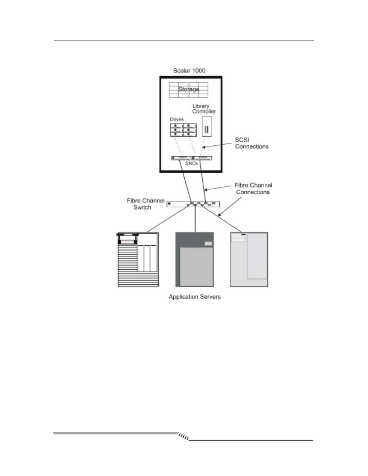
Figure 2-4 Indirect Fibre Channel Attachment
22 June 2004
Connectivity 2-15
Page 46

SCSI Connectivity
The Scalar 1000 can be directly connected to one or two SCSI
buses. Because each SCSI bus is independent, it can be Single
Ended, High Voltage Differential, or Low Voltage
Differential. Both ends of each bus must be terminated and a
terminator is shipped with each SCSI adapter card ordered.
The minimum configuration of a Scalar 1000 library requires
one SCSI adapter (Single Ended, High Voltage Differential, or
Low Voltage Differential).
Although the Scalar 1000 can be attached to a wide SCSI bus,
it is not a wide SCSI device and its SCSI ID must be in the
range of 0 to 7. See Figure 2-5.
2-16 System Description
Figure 2-5 Direct SCSI Attachment
6-00054-02 Rev A
Page 47

Scalar DLC Option
The Scalar 1000, through an optional Scalar Distributed
Library Control (Scalar DLC), provides the industry’s most
advanced combination of management and diagnostics.
The Scalar DLC attaches to the library SCSI bus.
The host continues to directly attach to the drives via a SCSI
Interface.
See the ADIC Scalar DLC documentation for detailed
description of the interfaces supported. See Figure 2-6.
Figure 2-6 Network Attachment
22 June 2004
Scalar DLC Option 2-17
Page 48

Remote Management Unit
The factory-installed Remote Management Unit (RMU) in
each system uses a standard web browser for remote library
access.
The supported browsers are:
• Microsoft Internet Explorer version 4.0 and above
• Netscape Navigator version 4.7 and above
With an RMU, you are able to do the following:
• Update RMU firmware
• Update library firmware
• Access the library status
• Make configuration changes
• Access the library Operator Panel
• Access Scalar 1000 documentation
• Retrieve library command and even t logs
The RMU supports Simple Network Management Protocol
(SNMP) version 2.0 and acts as an SNMP-server. The RMU
acquires Tape Alert 3.0 compatible information from the
library over the serial interface port and sends that
information to a SNMP manager. The RMU also detects a
power loss and generates a SNMP trap for notification.
2-18 System Description
6-00054-02 Rev A
Page 49

3
Safety
Overview . . . . . . . . . . . . . . . . . . . . . . . . . . . . . . . . . . . . . . . . . . . . . . . . . . . . . . . . . . . . . . .3-3
Intended Use . . . . . . . . . . . . . . . . . . . . . . . . . . . . . . . . . . . . . . . . . . . . . . . . . . . . . . . . . . . .3-3
Hazard Alert Messages . . . . . . . . . . . . . . . . . . . . . . . . . . . . . . . . . . . . . . . . . . . . . . . . . . . .3-3
Area of Application . . . . . . . . . . . . . . . . . . . . . . . . . . . . . . . . . . . . . . . . . . . . . . . . . . . . . . .3-5
Protective Devices . . . . . . . . . . . . . . . . . . . . . . . . . . . . . . . . . . . . . . . . . . . . . . . . . . . . . . . .3-5
Library Access . . . . . . . . . . . . . . . . . . . . . . . . . . . . . . . . . . . . . . . . . . . . . . . . . . . . . . .3-5
Mechanical Lock . . . . . . . . . . . . . . . . . . . . . . . . . . . . . . . . . . . . . . . . . . . . . . . . . .3-6
Main Circuit Breaker (Power) Switch . . . . . . . . . . . . . . . . . . . . . . . . . . . . . . . . . . . .3-6
Page 50

3-2 Safety
6-00054-02 Rev A
Page 51

Overview
3-
Note
In addition to the
safety
instructions in
this guide, local
and professional
safety rules
apply.
Intended Use
Hazard Alert Messages
Avoid dangerous situations while operating the Scalar 1000
by following all safety procedures and operating the
equipment carefully. Read and follow all instructions in this
guide.
It is mandatory that operators of the Scalar 1000 library
understand and comply with all instructions contained in this
guide and other related documentation.
This equipment is designed for processing magnetic tape
cartridges and any other application is not considered the
intended use. The user assumes all risk and ADIC shall not be
held liable for damage arising from unauthorized use of the
library.
ADIC classifies hazards in several categories. Table 3-1 shows
the relationship of the symbols, signal words, actual hazards,
and possible consequences.
Table 3-1 Hazard Alert Message
Symbol Damage to ... Signal Word Definition Consequence
DANGER Imminent hazardous
WARNING Potential hazardous
Persons
CAUTION Less hazardous
Persons
22 June 2004
situation
situation
situation
Imminent hazardous
electrical situation
Death or serious
injury
Possible death or
serious injury
Possible minor or
moderate injury
Death or serious
injury
Overview 3-3
Page 52

Table 3-1 Hazard Alert Message (Continued)
Symbol Damage to ... Signal Word Definition Consequence
Caution
Material
Person
Material
Caution
Warning
Static
Sensitive
Note
Specially emphasized paragraphs in this guide warn of
danger or draw attention to important information. These
paragraphs and their associated symbols include:
The danger exists of a fatal electric shock. At places
designated with this symbol, electrical current can be
present. Before starting any work, always confirm that all
electrical connections are free of electrical current.
This symbol indicates the presence of a laser.
Caution - use of controls or adjustments or performance of
procedures other than those specified herein may result in
hazardous radiation exposure.
Potential damaging
situation
Potential hazardous
situation
Potential electronic
damaging situation
Tips for operators No hazardous or
Important or useful
information
Possible damage
to the product or
environment
Possible death or
serious injury
Possible damage
to the product
damaging
consequences
No hazardous or
damaging
consequences
3-4 Safety
Warning
Caution
STATIC
SENSITIVE
When used with the signal word Warning, this symbol
warns of a dangerous situation that threatens personnel
with serious injury or death.
When used with the signal word Caution, this symbol
means that specific regulations, rules, notices, and working
procedures must be observed. Ignoring this symbol can lead
to equipment damage or destruction or to other property
damage.
This symbol indicates that the risk of equipment damage
exists due to static discharge.
6-00054-02 Rev A
Page 53

Note
Area of Application
Note
Other
manufacturer
documentation is
an integral part of
the Scalar 1000
documentation
set.
Protective Devices
This symbol draws attention to user tips. No dangerous or
damaging consequences for personnel or property are
associated with this symbol.
This symbol indicates important or useful information. No
dangerous or damaging consequences for personnel or
property are associated with this symbol.
This information applies to the entire Scalar 1000 family.
Further safety instructions for components used in the
equipment are not invalidated by these instructions.
The Scalar 1000 is equipped with the following protective
devices:
Warning
Warning
• Monitored locked access to the library
• Main Circuit Breaker switch
Library Access
The Scalar 1000 is completely surrounded by an enclosure.
The library can only be accessed through monitored access
doors.
The enclosure around the library separates the danger area of
the Scalar 1000 library from the normal working area. The
danger area of the library is the area in which personnel can
be injured by component movements.
Movements of mechanical components in the library can
cause serious injury. Access to the library is restricted to
authorized personnel only.
Look into the aisle before you apply library power to make
sure there are no obstructions or personnel present.
Mechanical movement within the library can cause serious
injury.
22 June 2004
Area of Application 3-5
Page 54

Mechanical Lock
The library access doors can only be opened with a key from
the outside. Authorized personnel are responsible for the
security of the key.
Main Circuit Breaker (Power) Switch
Switching off the Main Circuit Breaker switch removes all
power and causes the movement electronics to shut off. All
movements of the Accessor stop immediately. In case of
danger to personnel or property, immediately switch off the
Main Circuit Breaker switch.
Caution
Warning
Warning
Except in emergencies, stop the Scalar 1000 with the normal
shutdown procedure before switching off the Main Circuit
Breaker switch. ADIC is not responsible for damage caused
by improper use of the Main Circuit Breaker switch; such
risk lies entirely with the user.
Movements of mechanical components in the Scalar 1000
can cause serious injury. Before turning the Main Circuit
Breaker switch on and restarting the Scalar 1000, confirm
that no danger exists to personnel or property.
Look into the aisle before you apply library power to make
sure there are no obstructions or personnel present.
Mechanical movement within the library can cause serious
injury.
3-6 Safety
6-00054-02 Rev A
Page 55

4
Operation
Overview . . . . . . . . . . . . . . . . . . . . . . . . . . . . . . . . . . . . . . . . . . . . . . . . . . . . . . . . . . . . . . .4-3
Using the Operator Panel . . . . . . . . . . . . . . . . . . . . . . . . . . . . . . . . . . . . . . . . . . . . . . . . . .4-3
Starting the Scalar 1000 . . . . . . . . . . . . . . . . . . . . . . . . . . . . . . . . . . . . . . . . . . . . . . . . . . . .4-7
Shutting Down the Scalar 1000 . . . . . . . . . . . . . . . . . . . . . . . . . . . . . . . . . . . . . . . . . . . . .4-9
Normal Shutdown . . . . . . . . . . . . . . . . . . . . . . . . . . . . . . . . . . . . . . . . . . . . . . . . . . . .4-9
Emergency Shutdown . . . . . . . . . . . . . . . . . . . . . . . . . . . . . . . . . . . . . . . . . . . . . . . .4-10
Restarting the Scalar 1000 . . . . . . . . . . . . . . . . . . . . . . . . . . . . . . . . . . . . . . . . . . . . . . . . .4-11
Using the Remote Management Unit . . . . . . . . . . . . . . . . . . . . . . . . . . . . . . . . . . . . . . .4-11
Supported Browsers . . . . . . . . . . . . . . . . . . . . . . . . . . . . . . . . . . . . . . . . . . . . . . . . .4-12
System Administrator Responsibilities . . . . . . . . . . . . . . . . . . . . . . . . . . . . . . . . . .4-12
RMU Prerequisites . . . . . . . . . . . . . . . . . . . . . . . . . . . . . . . . . . . . . . . . . . . . . . . . . . .4-12
Setting up the RMU . . . . . . . . . . . . . . . . . . . . . . . . . . . . . . . . . . . . . . . . . . . . . . . . .4-13
Accessing the RMU . . . . . . . . . . . . . . . . . . . . . . . . . . . . . . . . . . . . . . . . . . . . . . . . . .4-14
Logging into the RMU . . . . . . . . . . . . . . . . . . . . . . . . . . . . . . . . . . . . . . . . . . . . . . . .4-14
Checking Status and General Information . . . . . . . . . . . . . . . . . . . . . . . . . . . . . . .4-14
Configuring Network Parameters . . . . . . . . . . . . . . . . . . . . . . . . . . . . . . . . . . . . . .4-15
Configuring SNMP . . . . . . . . . . . . . . . . . . . . . . . . . . . . . . . . . . . . . . . . . . . . . . . . . .4-16
Downloading the SNMP MIB File . . . . . . . . . . . . . . . . . . . . . . . . . . . . . . . . . .4-17
Configuring RMU Users . . . . . . . . . . . . . . . . . . . . . . . . . . . . . . . . . . . . . . . . . . . . . .4-17
Adding/Removing Users . . . . . . . . . . . . . . . . . . . . . . . . . . . . . . . . . . . . . . . . .4-17
Changing a Password . . . . . . . . . . . . . . . . . . . . . . . . . . . . . . . . . . . . . . . . . . . . .4-18
Configuring the Time and Date . . . . . . . . . . . . . . . . . . . . . . . . . . . . . . . . . . . . . . . .4-19
Synchronizing with an NTP Server . . . . . . . . . . . . . . . . . . . . . . . . . . . . . . . . .4-19
Updating Firmware . . . . . . . . . . . . . . . . . . . . . . . . . . . . . . . . . . . . . . . . . . . . . . . . . .4-20
Viewing Diagnostic Files (Library and RMU Logs) . . . . . . . . . . . . . . . . . . . . . . .4-20
Using the Operator Panel (via the RMU) . . . . . . . . . . . . . . . . . . . . . . . . . . . . . . . .4-21
Viewing Logs . . . . . . . . . . . . . . . . . . . . . . . . . . . . . . . . . . . . . . . . . . . . . . . . . . . . . . .4-21
Getting Help . . . . . . . . . . . . . . . . . . . . . . . . . . . . . . . . . . . . . . . . . . . . . . . . . . . . . . . .4-21
Page 56

4-2 Operation
6-00054-02 Rev A
Page 57

Overview
This chapter describes the Operator Panel, Scalar 1000 start
and shutdown procedures, and the Remote Management Unit
(RMU) operations and menus.
Using the Operator Panel
The Operator Panel is an interactive path between the
operator and the Scalar 1000. See Figure 4-1 on page 4-4.
Scalar 1000 operator can perform the following functions
listed below:
• Starting the Scalar 1000
• Shutting down the Scalar 1000
• Handling media
Refer to Inserting Media on page 6 and Ejecting Media on page
8 for media handling procedures. In the case of equipment
failures, the operator can perform media processing.
4-
22 June 2004
Overview 4-3
Page 58

4X20 LCD Panel
Speaker Vent
4-4 Operation
Figure 4-1 Operator Panel
6-00054-02 Rev A
Page 59

Table 4-1 illustrates and describes Operator Panel indicators.
Table 4-1 Operator Panel Indicators
Indicator Description
The Locked indicator illuminates when the Insert/Eject Station is locked.
While locked, no media may be added or removed through the Insert/Eject
Station.
The Power On indicator illuminates when power is applied to the Scalar 1000
library.
The Ready indicator illuminates when the Scalar 1000 is ready to accept
commands or execute Accessor movements.
Table 4-2 illustrates and describes Operator Panel
push-buttons.
Table 4-2 Operator Panel Push-Buttons
Push-Button Description
Use Up Arrow to:
• scroll the display to show the previous lines.
• move the cursor (>) up from selection to selection.
• increment the current value in a numerical entry field.
22 June 2004
Using the Operator Panel 4-5
Page 60

Table 4-2 Operator Panel Push-Buttons (Continued)
Push-Button Description
Use Down Arrow to:
• scroll the display to show next line.
• move the cursor (>) down from selection to selection.
• decrement the current value in a numerical entry field.
Use Enter to:
• select the current option as the next action to be performed by the library,
the cursor (>) indicates the chosen option.
• act as a TAB button to the next required entry field when multiple field
entries are being entered. In this case, the button cycles through all the entry
locations until the Accept option is chosen (with Y).
Use Escape to:
• leave the current menu and return to the previous menu, if it exists.
• Leave the Help menu and return to the previous menu.
Use Help to display help text for the current selected item if available. In this
mode, the Arrow buttons can be used to scroll through the help text and the
Escape button is used to exit help.
Use Ready to transition the library from a Ready state to Not Ready or Not
Ready to the Ready state.
Holding down the push-buttons will cycle through the
options. The longer the push-button is held down, the faster it
will cycle.
4-6 Operation
6-00054-02 Rev A
Page 61

Starting the Scalar 1000
Use the following procedure to start the Scalar 1000.
Caution
Expansion
Module
If an RMU is installed in the library, wait at least one minute
between powering down and powering up the li brary. This
allows the RMU to properly reset.
Step 1 Make sure that all doors are closed and
mechanically locked on the Control Module (CM)
and any Expansion Modules (EMs).
Step 2 Locate the Main Circuit Breaker switch in the lower
right corner at the back of the CM and each EM.
See Figure 4-2 for the location of the Main Circuit
Breaker switch.
Control
Module
Main Circuit Breaker Switches
Figure 4-2 Main Circuit Breaker Switch Locations (Back View of CM/EM)
22 June 2004
Starting the Scalar 1000 4-7
Page 62

Step 3 Set the Main Circuit Breaker switch on each EM to
ON.
Step 4 Set the Main Circuit Breaker switch on the CM to
ON.
Warning
Warning
Movements of mechanical components in the Scalar 1000
can cause serious injury. Before turning the Main Circuit
Breaker switch ON, confirm that no danger exists to
personnel or property.
Look into the aisle before you apply library power to make
sure there are no obstructions or personnel present.
Mechanical movement within the library can cause serious
injury.
Power is applied to the Scalar 1000. The CM embedded
software starts the boot process. The Power On indicator
illuminates and the Initial Screen displays status.
The firmware initiates a self test procedure, performs an
auto-configuration, and inventories the library. When
all firmware procedures are complete the Operator Panel
LCD screen displays the Main Screen. See Figure 4-3.
MAIN SCREEN
MM/DD/YY
Online.........Ready
HH/MM/SS
Idle
4-8 Operation
Figure 4-3 Main Screen
6-00054-02 Rev A
Page 63

Shutting Down the Scalar 1000
n
You can shutdown the Scalar 1000 using the normal
shutdown procedure (recommended for most situations) or
the emergency shutdown procedure.
Attentio
Except in emergency situations, shutdown the Scalar 1000
using the normal shutdown and not the emergency
shutdown procedure.
Normal Shutdown
Use the following shutdown procedure to shutdown the
Scalar 1000.
If an RMU is installed in the library, wait at least one minute
between powering down the library and powering up the
library. This allows the RMU to properly reset.
Step 1 If necessary, use the button to return to the
Main Menu. The selector defaults to the Mode
selection.
Step 2 Press the button.
Step 3 From the Mode screen, use the button to select
the Shutdown mode.
Step 4 Press the button.
The cursor moves to Shutdown mode and the state
automatically changes to Shutdown. The Accessor
completes the current task, returns to the home position,
and the reboot message appears. See Figure 4-4.
Figure 4-4 Reboot Message
22 June 2004
The library may now
be rebooted.
Step 5 Locate the Main Circuit Breaker switch in the lower
right corner at the back of the CM.
See Figure 4-2 on page 4-7 for the location of the
Main Circuit Breaker switch.
Shutting Down the Scalar 1000 4-9
Page 64

Step 6 Set the Main Circuit Breaker switch to OFF.
Power is removed from the Scalar 1000. All Accessor
movements halt immediately.
Step 7 Repeat Step 5 and Step 6 for each additional EM.
Emergency Shutdown
Use the following shutdown procedure only in emergency
situations.
Caution
Except in emergency situations, shutdown the Scalar 1000
using the normal shutdown procedure before switching off
the Main Circuit Breaker. Refer to Normal Shutdown on
page 4-9 for more information.
Step 1 Locate the Main Circuit Breaker switch in the lower
right corner at the back of the CM.
See Figure 4-2 on page 4-7 for the location of the
Main Circuit Breaker switch.
Step 2 Set the Main Circuit Breaker switch to OFF.
The Gripper does a controlled gravity descent to the
bottom and Accessor movements halt.
Step 3 For each additional EM:
a. Locate the Main Circuit Breaker switch at the
lower right corner in the back of the CM.
See Figure 4-2 on page 4-7 for the location of the
Main Circuit Breaker switch.
4-10 Operation
b. Set the circuit breaker to OFF.
Power is removed from the Scalar 1000. All Accessor
movements halt immediately.
6-00054-02 Rev A
Page 65

Restarting the Scalar 1000
Use the following procedure to restart the Scalar 1000.
Power up must be delayed by one minute after a power
down condition to allow the RMU to properly reset.
Step 1 If applicable, correct any situations that required
the Scalar 1000 shutdown.
Step 2 Refer to Starting the Scalar 1000 on page 4-7 for
instructions on the Scalar 1000 start procedure.
Using the Remote Management Unit
The Remote Management Unit (RMU) is a component in the
library that provides remote access to the library by means of
a Web browser. All functions listed here are available without
the need of a dedicated server (or separate software).
The RMU performs the following functions:
• Provides remote operation of all library Operator Panel
functions by means of a Web browser.
• Allows you to check the status of the system, firmware
levels, and other useful information.
• Updates RMU firmware.
• Supports Simple Network Management Protocol (SNMP)
version 2.0 and acts as an SNMP-server, generating SNMP
traps and responding to SNMP requests.
• Supports ADIC Library Management Information Base
(MIB) version 2.0.
• Acquires Tape Alert 3.0 information from the library and
sends that information to an SNMP manager.
• Detects a power loss and generates an SNMP trap for
notification.
• Enables the retrieval of library logs, and drive and RMU
diagnostic files.
• Allows RMU configuration changes such as network,
users, and date/time.
• Provides online access to documentation.
22 June 2004
Restarting the Scalar 1000 4-11
Page 66

The following screen is the opening screen of the RMU.
Supported Browsers
The RMU supports the following browsers:
• Microsoft Internet Explorer version 5.0 and above
• Netscape Navigator version 4.01 for Unix and 4.7X for
other environments
System Administrator Responsibilities
The System Administrator (SA) must setup the RMU for
proper operation. The SA responsibilities include establishing
a network address for the RMU and establishing the Uniform
Resource Locator (URL).
The network address consists of an Internet Protocol (IP)
address, subnet mask, and gateway IP address. Refer to RMU
Submenu on page 5-87 for information about setting the
network address via the Operator Panel.
After the network address has been established, the SA
should use the web browser to test the RMU and URL. Once
the URL has been verified and accounts have been created, the
SA can distribute the URL address to the potential RMU
users. The SA can delete users and change any user password.
RMU Prerequisites
The RMU requires a network address that consists of an
Internet Protocol (IP) address, subnet mask, and gateway IP
Address.
4-12 Operation
6-00054-02 Rev A
Page 67

Once you have this information, input it to the RMU by means
of the Operator Panel. For more information, see the
instructions that follow.
Setting up the RMU
Once you have obtained a network address for the RMU, enter
this information into the RMU by means of the library
Operator Panel.
To configure the RMU
Step 1 From Operator Panel Main Menu, select Setup
Library RMU.
The RMU Submenu is shown.
>Name...
IP...
Step 2 Select Name.
The Name Dialog is shown.
Name : webfoot3
Accept : N
Step 3 Enter the hostname using the Up, Down, and Next
buttons.
Step 4 Select Y to accept the changes.
Step 5 Select IP.
The IP Dialog is shown.
IP : 100<100.100.100
Sub: 255.255.255.255
Gat: 100.100.100.100
Accept: N
22 June 2004
Using the Remote Management Unit 4-13
Page 68

Note
For information
on determining
or setting your
RMU IP address,
see Setting up the
RMU on page
4-13.
Step 6 Using the Up, Down, and Next buttons, enter the IP
address, Subnet Mask, and Gateway IP address.
Step 7 Select Y to accept the changes.
Accessing the RMU
Before you begin using the RMU, make certain you have
configured your RMU with the correct network address.
To access the RMU
Step 1 Open a Web browser.
Step 2 Point your browser to the RMU IP address,
excluding any leading zeros. For example, if your
IP address is 182.073.056.205, go to the following
address: http://182.73.56.205.
The RMU user interface appears.
Logging into the RMU
Note
The default user
login and
password are
admin and secure,
respectively.
Some of the features of the RMU require you to log in.
To log into the RMU
• When prompted, enter your user name and password.
Note, the user name and password are case sensitive.
Checking Status and General Information
You can use the RMU to remotely check the status of a library
and obtain general information about the library. For
example, you can check drive status or get the firmware level
of your library.
To check status and obtain general information
Step 1 Click the Status tab.
The following information appears:
4-14 Operation
6-00054-02 Rev A
Page 69

• Library Status - Indicates whether the library is
online or offline.
• Drive Status - Indicates the type and quantity
of tape drives in the library.
• RMU User - Indicates the user name and IP
address of the current user.
• Hostname - Indicates the hostname of the
RMU.
• IP Address - Indicates the IP address for the
RMU connection.
• MAC Address - Indicates the Media Access
Control (MAC) address of the RMU. This is also
the serial number of the RMU.
• Library Serial # - Indicates the library serial
number.
• SNMP - Indicates whether SNMP requests and
alerts are enabled or disabled.
• SNMP Alerts - Indicates whether the SNMP
Alert notification feature is enabled or di sabled.
• Library Firmware - Indicates the current level
of library firmware.
• RMU Firmware - Indicates the current level of
RMU firmware.
Configuring Network Parameters
You can reconfigure the hostname, IP address, subnet
mask, and gateway address through the RMU. This feature
requires you to log in to the RMU. See Logging into the RMU
on page 4-14 for more information.
To configure the network parameters
Step 1 Click the Configuration tab.
Step 2 In the Network Configuration area, enter the new
hostname, IP address, subnet mask, and gateway
address.
Step 3 Click Submit and review your changes (indicated
in red).
Step 4 Enter your password and click Confirm to
complete the procedure.
The new values are saved. Note that you may need
to redirect your Web browser if you are logged out.
22 June 2004
Using the Remote Management Unit 4-15
Page 70

Configuring SNMP
Simple Network Management Protocol (SNMP) is a set of
protocols used to manage nodes on an IP network. You can
configure the RMU to send alerts to and respond to requests
from an SNMP management application.
To configure SNMP
Step 1 Click the Configuration tab.
Step 2 In the SNMP Configuration area, do the following:
• To enable or disable the feature, select ON or
OFF in the SNMP Enabled drop-down.
• To enable or disable SNMP alerts, select ON or
OFF in the Alerts Enabled drop-down. SNMP
must be enabled if you want SNMP alerts
enabled.
•In Manager, enter the SNMP server address.
•In Public Name, enter the name of the read-
only SNMP community.
•In Private Name, enter the name of the
read/write SNMP community.
Step 3 Click Submit and review your changes (indicated
in red).
Step 4 Enter your password and click Confirm to
complete the procedure.
The new values are saved. Note that you may need
to redirect your Web browser if you are logged out.
Step 5 Click Done.
You may be instructed to reboot the RMU.
4-16 Operation
6-00054-02 Rev A
Page 71

Downloading the SNMP MIB File
The SNMP Management Information Base (MIB) file allows
an SNMP management application to understand the SNMP
database and alerts generated by the RMU. If you are running
an SNMP management application and need the library MIB,
you can download it by means of the RMU.
To download the SNMP MIB file
Step 1 Click SNMP MIB in the left pane of the RMU
interface.
Step 2 Right-click Download SNMP MIB and click Save
Target As.
Step 3 Browse to your SNMP management server and
click Save.
You will need to load the MIB file into the SNMP
management application.
Configuring RMU Users
You can add unique users to the RMU. How ever, only one
administrator-level user is allowed, and it is automatically
given the user name admin.
Adding/Removing Users
Only the admin account can add or remove users.
To add or remove a user
Step 1 When prompted, log in as admin.
Step 2 Click the Configuration tab.
Step 3 In the User Configuration area, do one of the
22 June 2004
following:
• If you are adding a user:
a. In the Management Action drop-down,
click Create User.
b. In Edit New, enter the new user name.
Using the Remote Management Unit 4-17
Page 72

c. In Password, enter the new user’s
password and then confirm it in Re-enter
Password.
• If you are deleting a user:
a. In the Management Action drop-down,
click Delete User.
b. In Select One, select the user you want to
remove.
Step 4 Click Submit and review your changes (indicated
in red).
Step 5 Enter the admin password and click Confirm to
complete the procedure.
Changing a Password
At any time, you can change your RMU password. If you are
the administrator, you can also change other users’
passwords.
To change a password
Note
Only the admin
can modify
another user’s
password.
Step 1 Click the Configuration tab.
Step 2 In the User Configuration area, select Change User
Password from the Management Action
drop-down.
Step 3 If not already selected, select the appropriate user
account from the Select One drop-down.
Step 4 In Password, enter the new user’s password and
then confirm it in Re-enter Password.
Step 5 Click Submit and review your changes (indicated
in red).
Step 6 Enter your password and click Confirm to
complete the procedure.
4-18 Operation
6-00054-02 Rev A
Page 73

Note
If using a time
server, the
Scalar 1000
synchronizes
with the RMU.
Configuring the Time and Date
You can configure the date and time for the RMU. The date
and time will be used in the RMU log file to report when
events occurred.
To configure the date and time
Step 1 Click the Configuration tab.
Step 2 Enter the date and time in the Date and Time area.
Step 3 Click Submit and review your changes (indicated
in red).
Step 4 Enter your password and click Confirm to
complete the procedure.
Synchronizing with an NTP Server
You can connect the RMU to a network time (NTP) server to
automatically set the time.
To synchronize with an NTP server
Step 1 Click the Configuration tab.
Step 2 In the Date and Time area, select ON from the
Synchronization with NTP Server drop-down
menu.
Step 3 In the NTP Server IP Address field, enter the IP
Step 4 In the Timezone field, enter the time zone deviation
Step 5 Click Submit and review your changes (indicated
Step 6 Enter your password and click Confirm to
22 June 2004
address of the NTP server.
for the NTP server. To get a list of timezone offsets,
click list of timezones.
in red).
complete the procedure.
Using the Remote Management Unit 4-19
Page 74

Updating Firmware
You can update firmware for the RMU. Before you update
firmware, you need to have the firmware file in a location that
is accessible from the RMU interface. Firmware updates can
be found on www.adic.com.
To update firmware
Step 1 Click the Firmware tab.
Step 2 Select the firmware you would like to update.
Step 3 Click Browse and browse to the location of the
firmware update file.
Note
Downloading
firmware can take
several minutes.
Step 4 Click Update Firmware.
The firmware updates. If the RMU was selected for
a firmware update, the RMU will reboot.
Viewing Diagnostic Files (Library and RMU Logs)
From the RMU, you can view the diagnostic information
(logs) for the attached library and RMU. This information can
assist technical support personnel when diagnosing
problems.
To view diagnostic files
Step 1 Click the Diagnostics file tab.
Step 2 Select the file you would like to view. The available
options are:
• Library Command Log - Provides an event
(command, errors, and so on) log for the
library.
• Library Error Log - Same as the Library
Command Log.
• RMU Support Log - Provides support logs for
the RMU.
• RMU Error Log - Provides error logs for the
RMU.
4-20 Operation
6-00054-02 Rev A
Page 75

Step 3 Click Retrieve selected file.
The file loads.
Step 4 Click Display File to view the file in a separate
browser window.
Using the Operator Panel (via the RMU)
The RMU provides access to the library by means of a virtual
Operator Panel.
To use the Operator Panel
•Click the Operator panel tab.
A graphical representation of the Operator Panel appears.
You can click the softkeys and control the library the
same way that you would from the front of the library. For
more information on the Operator Panel, see Using the
Operator Panel on page 4-3.
Viewing Logs
You can view the most current entries in the library command
log without downloading the entire log file.
To view the log
•Click the Logs tab.
The command log appears with the most recent entry at
the top of the list.
Getting Help
The RMU provides access to help for the following items:
• Contents - Provides a description of each of the tabs on
the RMU interface.
• Documentation - Provides a link to the user
documentation for the library.
• SNMP MIB - Provides information on the SNMP
MIB file. For more information, see Configuring SNMP on
page 4-16.
• Support - Provides information on contacting technical
support.
22 June 2004
Using the Remote Management Unit 4-21
Page 76

• Version - Provides the current revision level of the RMU
firmware.
To get help
• Click on the item in the left pane of the RMU interface.
The information appears in a separate browser window.
4-22 Operation
6-00054-02 Rev A
Page 77

5
Menus and
Commands
Overview . . . . . . . . . . . . . . . . . . . . . . . . . . . . . . . . . . . . . . . . . . . . . . . . . . . . . . . . . . . . . . .5-5
Using the Operator Panel Menu . . . . . . . . . . . . . . . . . . . . . . . . . . . . . . . . . . . . . . . . . . . .5-5
Accessing the Menu . . . . . . . . . . . . . . . . . . . . . . . . . . . . . . . . . . . . . . . . . . . . . . . . . . .5-5
Special Characters or Cursors . . . . . . . . . . . . . . . . . . . . . . . . . . . . . . . . . . . . . . . . . .5-6
Help Button . . . . . . . . . . . . . . . . . . . . . . . . . . . . . . . . . . . . . . . . . . . . . . . . . . . . . . . . . .5-8
Operator Intervention Message . . . . . . . . . . . . . . . . . . . . . . . . . . . . . . . . . . . . . . . . .5-8
Main Menu . . . . . . . . . . . . . . . . . . . . . . . . . . . . . . . . . . . . . . . . . . . . . . . . . . . . . . . . . . . . . .5-9
Mode Dialog . . . . . . . . . . . . . . . . . . . . . . . . . . . . . . . . . . . . . . . . . . . . . . . . . . . . . . . . . . . .5-10
Status Menu . . . . . . . . . . . . . . . . . . . . . . . . . . . . . . . . . . . . . . . . . . . . . . . . . . . . . . . . . . . .5-12
Library Submenu . . . . . . . . . . . . . . . . . . . . . . . . . . . . . . . . . . . . . . . . . . . . . . . . . . . .5-13
SCSI Submenu . . . . . . . . . . . . . . . . . . . . . . . . . . . . . . . . . . . . . . . . . . . . . . . . . . .5-13
Mode Parms Dialog . . . . . . . . . . . . . . . . . . . . . . . . . . . . . . . . . . . . . . . . . . .5-14
Element Address . . . . . . . . . . . . . . . . . . . . . . . . . . . . . . . . . . . . . . . . . 5-15
Mixed-Media Support. . . . . . . . . . . . . . . . . . . . . . . . . . . . . . . . . . . . . 5-15
Parity . . . . . . . . . . . . . . . . . . . . . . . . . . . . . . . . . . . . . . . . . . . . . . . . . . . 5-17
LCD . . . . . . . . . . . . . . . . . . . . . . . . . . . . . . . . . . . . . . . . . . . . . . . . . . . . 5-18
Reservations Dialog . . . . . . . . . . . . . . . . . . . . . . . . . . . . . . . . . . . . . . . . . . .5-19
System Dialog . . . . . . . . . . . . . . . . . . . . . . . . . . . . . . . . . . . . . . . . . . . . . . . . . . .5-20
Element Dialog . . . . . . . . . . . . . . . . . . . . . . . . . . . . . . . . . . . . . . . . . . . . . . . . . .5-22
Logs Submenu . . . . . . . . . . . . . . . . . . . . . . . . . . . . . . . . . . . . . . . . . . . . . . . . . . .5-26
Command Log Dialog . . . . . . . . . . . . . . . . . . . . . . . . . . . . . . . . . . . . . . . . .5-26
Error Log Dialog. . . . . . . . . . . . . . . . . . . . . . . . . . . . . . . . . . . . . . . . . . . . . .5-28
Drive Error Log Dialog . . . . . . . . . . . . . . . . . . . . . . . . . . . . . . . . . . . . . . . .5-30
Drives Submenu . . . . . . . . . . . . . . . . . . . . . . . . . . . . . . . . . . . . . . . . . . . . . . . . . . . . .5-30
Drive State Dialog . . . . . . . . . . . . . . . . . . . . . . . . . . . . . . . . . . . . . . . . . . . . . . . .5-31
Media Info Dialog . . . . . . . . . . . . . . . . . . . . . . . . . . . . . . . . . . . . . . . . . . . . . . . .5-32
Commands Menu . . . . . . . . . . . . . . . . . . . . . . . . . . . . . . . . . . . . . . . . . . . . . . . . . . . . . . .5-35
Park . . . . . . . . . . . . . . . . . . . . . . . . . . . . . . . . . . . . . . . . . . . . . . . . . . . . . . . . . . . . . . .5-36
Move Submenu . . . . . . . . . . . . . . . . . . . . . . . . . . . . . . . . . . . . . . . . . . . . . . . . . . . . . .5-36
Position to Elem Dialog . . . . . . . . . . . . . . . . . . . . . . . . . . . . . . . . . . . . . . . . . . .5-37
Page 78

Move Media Dialog . . . . . . . . . . . . . . . . . . . . . . . . . . . . . . . . . . . . . . . . . . . . . .5-39
Inventory Dialog . . . . . . . . . . . . . . . . . . . . . . . . . . . . . . . . . . . . . . . . . . . . . . . . . . . .5-43
Insert/Eject Submenu . . . . . . . . . . . . . . . . . . . . . . . . . . . . . . . . . . . . . . . . . . . . . . . .5-45
Insert Screen . . . . . . . . . . . . . . . . . . . . . . . . . . . . . . . . . . . . . . . . . . . . . . . . . . . . .5-45
Insert Clean Tape Dialog . . . . . . . . . . . . . . . . . . . . . . . . . . . . . . . . . . . . . . . . . .5-47
Eject Dialog . . . . . . . . . . . . . . . . . . . . . . . . . . . . . . . . . . . . . . . . . . . . . . . . . . . . .5-52
Eject Clean Tape Submenu . . . . . . . . . . . . . . . . . . . . . . . . . . . . . . . . . . . . . . . .5-55
Expired Tapes . . . . . . . . . . . . . . . . . . . . . . . . . . . . . . . . . . . . . . . . . . . . . . . .5-55
By Coordinate Dialog. . . . . . . . . . . . . . . . . . . . . . . . . . . . . . . . . . . . . . . . . .5-57
By Volser Dialog . . . . . . . . . . . . . . . . . . . . . . . . . . . . . . . . . . . . . . . . . . . . . .5-60
Database Menu . . . . . . . . . . . . . . . . . . . . . . . . . . . . . . . . . . . . . . . . . . . . . . . . . . . . . . . . .5-62
Media Dialog . . . . . . . . . . . . . . . . . . . . . . . . . . . . . . . . . . . . . . . . . . . . . . . . . . . . . . . .5-63
Element Dialog . . . . . . . . . . . . . . . . . . . . . . . . . . . . . . . . . . . . . . . . . . . . . . . . . . . . . .5-64
Config Dialog . . . . . . . . . . . . . . . . . . . . . . . . . . . . . . . . . . . . . . . . . . . . . . . . . . . . . . .5-67
Advanced Dialog . . . . . . . . . . . . . . . . . . . . . . . . . . . . . . . . . . . . . . . . . . . . . . . . . . . .5-69
Learn Dialog . . . . . . . . . . . . . . . . . . . . . . . . . . . . . . . . . . . . . . . . . . . . . . . . . . . .5-69
Manipulate Get . . . . . . . . . . . . . . . . . . . . . . . . . . . . . . . . . . . . . . . . . . . . . . . . . .5-70
Manipulate Put . . . . . . . . . . . . . . . . . . . . . . . . . . . . . . . . . . . . . . . . . . . . . . . . . .5-70
Setup Menu . . . . . . . . . . . . . . . . . . . . . . . . . . . . . . . . . . . . . . . . . . . . . . . . . . . . . . . . . . . .5- 7 1
Library Submenu . . . . . . . . . . . . . . . . . . . . . . . . . . . . . . . . . . . . . . . . . . . . . . . . . . . .5-72
SCSI Submenu . . . . . . . . . . . . . . . . . . . . . . . . . . . . . . . . . . . . . . . . . . . . . . . . . . .5-73
Target ID Dialog . . . . . . . . . . . . . . . . . . . . . . . . . . . . . . . . . . . . . . . . . . . . . .5-74
Parity Dialog . . . . . . . . . . . . . . . . . . . . . . . . . . . . . . . . . . . . . . . . . . . . . . . . .5-75
Ports Dialog . . . . . . . . . . . . . . . . . . . . . . . . . . . . . . . . . . . . . . . . . . . . . . . . . .5-76
Host Dialog . . . . . . . . . . . . . . . . . . . . . . . . . . . . . . . . . . . . . . . . . . . . . . . . . . . . .5-77
Trace Dialog . . . . . . . . . . . . . . . . . . . . . . . . . . . . . . . . . . . . . . . . . . . . . . . . . . . . .5-78
Security Dialog . . . . . . . . . . . . . . . . . . . . . . . . . . . . . . . . . . . . . . . . . . . . . . . . . .5-79
Switching Security From Off to On . . . . . . . . . . . . . . . . . . . . . . . . . . . . . .5-79
Switching Security From On to Off . . . . . . . . . . . . . . . . . . . . . . . . . . . . . .5-81
Changing the Password. . . . . . . . . . . . . . . . . . . . . . . . . . . . . . . . . . . . . . . .5-82
Media Dialog . . . . . . . . . . . . . . . . . . . . . . . . . . . . . . . . . . . . . . . . . . . . . . . . . . . .5-84
Emulate Dialog . . . . . . . . . . . . . . . . . . . . . . . . . . . . . . . . . . . . . . . . . . . . . . . . . .5-86
RMU Submenu . . . . . . . . . . . . . . . . . . . . . . . . . . . . . . . . . . . . . . . . . . . . . . . . . .5-87
Name Dialog . . . . . . . . . . . . . . . . . . . . . . . . . . . . . . . . . . . . . . . . . . . . . . . . .5-87
IP Dialog. . . . . . . . . . . . . . . . . . . . . . . . . . . . . . . . . . . . . . . . . . . . . . . . . . . . .5-88
Advanced Dialog . . . . . . . . . . . . . . . . . . . . . . . . . . . . . . . . . . . . . . . . . . . . . . . .5-89
Drives Dialog . . . . . . . . . . . . . . . . . . . . . . . . . . . . . . . . . . . . . . . . . . . . . . . . . . . . . . .5-91
Cleaning Submenu . . . . . . . . . . . . . . . . . . . . . . . . . . . . . . . . . . . . . . . . . . . . . . . . . . .5-93
Drives Dialog . . . . . . . . . . . . . . . . . . . . . . . . . . . . . . . . . . . . . . . . . . . . . . . . . . . .5-93
Media Dialog . . . . . . . . . . . . . . . . . . . . . . . . . . . . . . . . . . . . . . . . . . . . . . . . . . . .5-94
View Dialog . . . . . . . . . . . . . . . . . . . . . . . . . . . . . . . . . . . . . . . . . . . . . . . . . . . . .5-96
Utils Menu . . . . . . . . . . . . . . . . . . . . . . . . . . . . . . . . . . . . . . . . . . . . . . . . . . . . . . . . . . . . .5-97
Library Submenu . . . . . . . . . . . . . . . . . . . . . . . . . . . . . . . . . . . . . . . . . . . . . . . . . . . .5-97
Screen Dialog . . . . . . . . . . . . . . . . . . . . . . . . . . . . . . . . . . . . . . . . . . . . . . . . . . . .5-98
Audio Dialog . . . . . . . . . . . . . . . . . . . . . . . . . . . . . . . . . . . . . . . . . . . . . . . . . . .5-100
Dump . . . . . . . . . . . . . . . . . . . . . . . . . . . . . . . . . . . . . . . . . . . . . . . . . . . . . . . . .5-101
Time Dialog . . . . . . . . . . . . . . . . . . . . . . . . . . . . . . . . . . . . . . . . . . . . . . . . . . . .5-101
5-2 Menus and Commands
6-00054-02 Rev A
Page 79

Date Dialog . . . . . . . . . . . . . . . . . . . . . . . . . . . . . . . . . . . . . . . . . . . . . . . . . . . .5-102
Drives Submenu . . . . . . . . . . . . . . . . . . . . . . . . . . . . . . . . . . . . . . . . . . . . . . . . . . . .5-103
Update Microcode Dialog . . . . . . . . . . . . . . . . . . . . . . . . . . . . . . . . . . . . . . . .5-104
Clean Drives Dialog . . . . . . . . . . . . . . . . . . . . . . . . . . . . . . . . . . . . . . . . . . . . .5 -108
Unload Drives Dialog . . . . . . . . . . . . . . . . . . . . . . . . . . . . . . . . . . . . . . . . . . . .5-110
Initialize Submenu . . . . . . . . . . . . . . . . . . . . . . . . . . . . . . . . . . . . . . . . . . . . . .5-111
Communication. . . . . . . . . . . . . . . . . . . . . . . . . . . . . . . . . . . . . . . . . . . . . .5-112
SCSI. . . . . . . . . . . . . . . . . . . . . . . . . . . . . . . . . . . . . . . . . . . . . . . . . . . . . . . .5-112
Service Menu . . . . . . . . . . . . . . . . . . . . . . . . . . . . . . . . . . . . . . . . . . . . . . . . . . . . . . . . . .5-113
Start Dialog . . . . . . . . . . . . . . . . . . . . . . . . . . . . . . . . . . . . . . . . . . . . . . . . . . . . . . . .5-114
Diags Submenu . . . . . . . . . . . . . . . . . . . . . . . . . . . . . . . . . . . . . . . . . . . . . . . . . . . . .5-116
DI/DO Submenu . . . . . . . . . . . . . . . . . . . . . . . . . . . . . . . . . . . . . . . . . . . . . . .5-117
Loopback Dialog. . . . . . . . . . . . . . . . . . . . . . . . . . . . . . . . . . . . . . . . . . . . .5-117
Sensors Submenu . . . . . . . . . . . . . . . . . . . . . . . . . . . . . . . . . . . . . . . . . . . .5-118
Wrap Dialog. . . . . . . . . . . . . . . . . . . . . . . . . . . . . . . . . . . . . . . . . . . . 5-118
Real Time . . . . . . . . . . . . . . . . . . . . . . . . . . . . . . . . . . . . . . . . . . . . . . 5-120
Locks Dialog . . . . . . . . . . . . . . . . . . . . . . . . . . . . . . . . . . . . . . . . . . . . . . . .5-121
Gripper Submenu . . . . . . . . . . . . . . . . . . . . . . . . . . . . . . . . . . . . . . . . . . . . . . .5-121
Get/Put Storage Dialog . . . . . . . . . . . . . . . . . . . . . . . . . . . . . . . . . . . . . . .5-122
Get/Put Drives Dialog. . . . . . . . . . . . . . . . . . . . . . . . . . . . . . . . . . . . . . . .5-125
Step Dialog. . . . . . . . . . . . . . . . . . . . . . . . . . . . . . . . . . . . . . . . . . . . . . . . . .5-128
Scanner Submenu . . . . . . . . . . . . . . . . . . . . . . . . . . . . . . . . . . . . . . . . . . . . . . .5-130
Adjust Dialog. . . . . . . . . . . . . . . . . . . . . . . . . . . . . . . . . . . . . . . . . . . . . . . .5-130
Trigger Dialog . . . . . . . . . . . . . . . . . . . . . . . . . . . . . . . . . . . . . . . . . . . . . . .5-131
Fiducial Test Dialog . . . . . . . . . . . . . . . . . . . . . . . . . . . . . . . . . . . . . . . . . .5-132
Accessor Submenu . . . . . . . . . . . . . . . . . . . . . . . . . . . . . . . . . . . . . . . . . . . . . .5-133
Move Dialog . . . . . . . . . . . . . . . . . . . . . . . . . . . . . . . . . . . . . . . . . . . . . . . .5-134
Step Dialog. . . . . . . . . . . . . . . . . . . . . . . . . . . . . . . . . . . . . . . . . . . . . . . . . .5-135
SelfTest Dialog . . . . . . . . . . . . . . . . . . . . . . . . . . . . . . . . . . . . . . . . . . . . . . . . . .5-136
PowerSup Dialog . . . . . . . . . . . . . . . . . . . . . . . . . . . . . . . . . . . . . . . . . . . . . . .5-137
Teach Submenu . . . . . . . . . . . . . . . . . . . . . . . . . . . . . . . . . . . . . . . . . . . . . . . . . . . .5-138
Teach New Dialog . . . . . . . . . . . . . . . . . . . . . . . . . . . . . . . . . . . . . . . . . . . . . . .5-138
Teach Current Dialog . . . . . . . . . . . . . . . . . . . . . . . . . . . . . . . . . . . . . . . . . . . .5-140
SAC Dialog . . . . . . . . . . . . . . . . . . . . . . . . . . . . . . . . . . . . . . . . . . . . . . . . . . . . . . . .5-143
Demo Dialog . . . . . . . . . . . . . . . . . . . . . . . . . . . . . . . . . . . . . . . . . . . . . . . . . . . . . . .5-143
Advanced Dialog . . . . . . . . . . . . . . . . . . . . . . . . . . . . . . . . . . . . . . . . . . . . . . . . . . .5-146
Other Dialog . . . . . . . . . . . . . . . . . . . . . . . . . . . . . . . . . . . . . . . . . . . . . . . . . . . . . . .5-147
About Screen . . . . . . . . . . . . . . . . . . . . . . . . . . . . . . . . . . . . . . . . . . . . . . . . . . . . . . . . . .5-148
22 June 2004
5-3
Page 80

5-4 Menus and Commands
6-00054-02 Rev A
Page 81

Overview
5-
This chapter describes the Scalar 1000 menus and commands.
Note
The information
menus are not
dynamically
updated. To view
changes, reselect
the menu that
was changed.
Using the Operator Panel Menu
The Operator Panel is a menu-driven interface that provides
library status and current operating parameters to the
Scalar 1000 Library.
Through this interface you may select, view, or change many
of the library parameters. See the Operator Panel directory
structure in Figure 5-1 on page 5-7.
Use the Operator Panel push-buttons to access each menu or
menu option. All menus and their respective options are
grouped according to function.
Accessing the Menu
Proceed as follows to use the Operator Panel menu buttons to
select menu options:
Step 1 Press the (Up arrow) button or the (Down
arrow) button to scroll through the current
selection, or to move the cursor to a new option.
Step 2 Press the (Enter) button to activate your
selection.
Step 3 Press the (Escape) button to return to the
22 June 2004
previous option.
Each time you press the Escape button, you will
move back one step in the menu tree. If you
continue to press Escape, you will return to the
Main Menu.
Overview 5-5
Page 82

Special Characters or Cursors
A menu option can be preceded or followed by one or more
of the following special characters or cursors:
Note
If no special
character follows
the option, the
selected action
will commence
immediately.
When this character follows the option, the next
menu contains more options.
... When these characters follow the option, the next
menu requests or supplies information.
> When this cursor precedes the option, the option is
available for selection. Press the button to select
the option. Press the button to view information
about the option. Press the or button to
select between the previous or next options.
< When this cursor follows the option, you can scroll
predefined values with the and buttons for
the selected option.
^ When this cursor appears below the option, you can
scroll predefined values with the and
buttons for the selected option.
Refer to the Using the Operator Panel on page 4-3 for detailed
information.
5-6 Menus and Commands
6-00054-02 Rev A
Page 83

Figure 5-1 Operator Panel Directory Structure
22 June 2004
Using the Operator Panel Menu 5-7
Page 84

Help Button
Help is common to all menus, submenus, dialogs, and
screens. Using Help while the cursor (< or >) is at a desired
location, provides information about that entry.
To use Help proceed as follows:
Step 1 Press the (Help) button to view help on a menu
Step 2 Press the (Up arrow) button or the (down
Step 3 Press the (Escape) button to return to the
selection.
The help text appears for the current selection.
arrow) button to move between help continuation
screens.
previous selection.
Each time you press the Escape button, you will
move back one step in the menu tree. If you
continue to press Escape, you will return to the
Main Menu.
Operator Intervention Message
If an error condition causes an operator intervention message
to appear, refer to Table 7-2 Operator Intervention Messages
on page 7-23 and Table 7-3 Error Log Reporting on page 7-28.
5-8 Menus and Commands
6-00054-02 Rev A
Page 85

Main Menu
Path: Main Menu
Note
The button
can always be
used to escape to
the previous
menu.
The Main Menu is the first available menu after the Main
screen. Refer to Using the Operator Panel on page 4-3 for
detailed Main Menu information. All subsequent menus and
options are selected from the Main Menu. See Figure 5-2.
>Mode... Setup
Status Utils
Commands Service
Database About
...
Figure 5-2 Main Menu
Depending on your selection, you have the following options:
• Mode Dialog on page 5-10
• Status Menu on page 5-12
• Commands Menu on page 5-35
• Database Menu on page 5-62
• Setup Menu on page 5-71
• Utils Menu on page 5-97
• Service Menu on page 5-113
• About Screen on page 5-148
22 June 2004
Main Menu 5-9
Page 86

Mode Dialog
Path: Main Menu Mode Dialog
Use the Mode Dialog to change the library operating mode.
For example, you can set the library to Online or Offline.
See Figure 5-3.
Offline ....... Ready
>Online
Figure 5-3 Mode Dialog
Ready
Accept: N
Parameter Value
Note
If Shutdown is
selected for the
Mode parameter,
Shutdown is
automatically
displayed for the
State parameter.
Mode Online
Offline
Shutdown
State Ready
Not Ready
Accept Y to accept changes
N to reject changes
When toggling between the Ready and Not Ready states,
the following two screens, refer to Figure 5-4 and
Figure 5-5 appear. When Shutdown is selected, the
Shutdown Screen appears. See Figure 5-6.
Changing state to:
>READY<
Figure 5-4 Ready Screen
5-10 Menus and Commands
Changing state to:
>NOT READY<
Figure 5-5 Not Ready Screen
6-00054-02 Rev A
Page 87

The library can now
be rebooted.
Figure 5-6 Shutdown Screen
Table 5-1 details the state and mode descriptions available
under the Mode screen.
Table 5-1 Operating State and Mode
State Mode Description
Ready Online The normal host controlling condition. Host commands are
processed.
Offline The normal operator controlling condition. Operator
commands are processed. Most host commands are not
processed.
Not Ready Online Aisle power is not present. Host commands not involving the
Accessor are processed.
Offline Aisle power is not present. Most operator and host commands
are not processed.
Shutdown Shutdown Properly shuts down the library. All commands issued by the
host are completed, and no other commands are accepte d. The
RUM issues SNMP traps and then also shuts down. The
library (and RMU) must be power cycled to leave this state.
22 June 2004
Mode Dialog 5-11
Page 88

Status Menu
Path: Main Menu Status Menu
Use the Status Menu to access views of your library
operating statistics. See Figure 5-7.
>Library
Figure 5-7 Status Menu
Depending on your selection, you have the following options:
• Library Submenu on page 5-13
• Drives Submenu on page 5-30
Drives
5-12 Menus and Commands
6-00054-02 Rev A
Page 89

Library Submenu
Path: Main Menu Status Menu Library Submenu
Use the Library Submenu to access SCSI, System, Element,
and Log files for viewing or printing history. See Figure 5-8.
>SCSI
System
Element...
Logs
Figure 5-8 Library Submenu
Depending on your selection, you have the following options:
• SCSI Submenu
• System Dialog on page 5-20
• Element Dialog on page 5-22
• Logs Submenu on page 5-26
SCSI Submenu
...
Path: Main Menu Status Menu Library
Submenu SCSI Submenu
Use the SCSI Submenu to view different SCSI parameter. See
Figure 5-9.
>Mode Parms...
Reservations...
Figure 5-9 SCSI Submenu
Depending on your selection, one of the following appears:
• Mode Parms Dialog on page 5-14
• Reservations Dialog on page 5-19
22 June 2004
Status Menu 5-13
Page 90

Mode Parms Dialog
Path: Main Menu Status Menu Library
Submenu SCSI Submenu Mode Parms Dialog
Use Mode Parms to view the current, default, or saved Mode
Parameter pages. For example, you can view an individual
element address or see if the library has Mixed-Media
Support enabled. See Figure 5-10 and refer to the Scalar 1000
SCSI Reference Manual for additional information about the
Scalar 1000 Mode Parameters.
Select Mode Parms:
ELEMENT ADDRESS <
and Type: CURRENT
Accept: N
Figure 5-10 Mode Parms Dialog
Parameter Value
Mode Parms Element Address
Mixed-Media
Parity
LCD
Type Current
Default
Saved
Accept Y to accept changes
N to reject changes
If Y is selected for the Accept parameter value, one
of the response screens appears. Refer to Figure 5-11 on
page 5-15. Otherwise, the changed parameters continue
to display but no action is taken.
5-14 Menus and Commands
6-00054-02 Rev A
Page 91

Element Address
Use Element Address to check current, default, or saved
addresses of the Accessor, storage cell, I/E station, or tape
drives. See Figure 5-11.
Base MT : 00001
Base ST : 04096
Base IE : 00016
Base DT : 00256
Figure 5-11 Element Address Screen
Parameter Value
Base MT Current, default, or saved base
Accessor address
Base ST Current, default, or saved base
Storage Cell address
Base IE Current, default, or saved base
Insert/Eject station address
Base DT Current, default, or saved base
tape drive address
Mixed-Media Support
Use Mixed-Media Support to see barcode processing or if
the read element, unique additional sense code qualifier, or
mixed mode is enabled.
When Mixed-Media Support is selected, the Mixed-Media
screen appears. See Figure 5-12.
MediaID :N Mixed: N
Ext RES : N
Ext ASCQ : N
Ext BC : N
Figure 5-12 Mixed-Media Screen
22 June 2004
Status Menu 5-15
Page 92

Parameter Value
Media ID Yes indicates that the library is
processing barcode media
identifiers.
No indicates that the library is
not processing barcode media
identifiers. If the library is
NOT operating in Media ID
mode, the Extended RES,
Extended ASCQ, and
Extended barcode are not
applicable.
Ext RES Yes indicates that Extended
Read Element Status is
enabled to show element and
media domains/types.
No indicates that Extended
Read Element Status is
disabled.
Ext ASCQ Yes indicates that Vendor
Unique Additional Sense
Code Qualifiers are currently
enabled.
No indicates that Vendor
Unique Additional Sense
Qualifiers are currently
disabled.
Ext BC Yes indicates that reported
barcode will include the media
type identifier.
No indicates that reported
barcode will not include the
media type identifier.
5-16 Menus and Commands
6-00054-02 Rev A
Page 93

Mixed Yes indicates that the library is
operating in mixed mode and
allows for non-installed
devices which may be
addressable by the SCSI host.
No indicates that the library is
not operating in mixed mode
and all non-installed devices/
cells will NOT be addressable
by the SCSI host.
Parity
Use Parity to view the current, default, or saved parity.
This view also displays the retries that are allowed in each
selection. See Figure 5-13.
Parity : Yes
Retries: 001
Figure 5-13 Parity Screen
Parameter Value
Parity Yes indicates that current,
Retries Indicates the current number
default, or saved SCSI parity is
enabled.
No indicates that current,
default, or saved SCSI parity is
is disabled.
of transmission retries allowed
(000–999) due to SCSI parity
errors
22 June 2004
Status Menu 5-17
Page 94

LCD
Use LCD to view current, default, or saved library security.
See Figure 5-14.
Security: Disabled
Line : 1<
MAIN MENU
(default)
Figure 5-14 LCD Dialog
Parameter Value
Security Disabled indicates that library
security is currently disabled.
Enabled indicates that library
security is currently enabled.
Line Indicates the currently
displayed text line (1–4).
Text Corresponding line of main
menu text with up to
20 characters.
default Displays which of the three
modes (current, default, or
saved) is being displayed.
5-18 Menus and Commands
6-00054-02 Rev A
Page 95

Reservations Dialog
Path: Main Menu Status Menu Library
Submenu SCSI Submenu Reservations Dialog
Use the Reservations Dialog to view a specific element,
or the entire library. See Figure 5-15.
This reservation remains in effect until:
• The initiator that made the reservation sends another
command with the same Reservation Identification
number (this supersedes any previous reservation).
• The initiator that made the reservation sends a RELEASE
command.
A reset or a power-on of the library is performed.
Bus : 0 < Host ID : 0
Reservation ID: Any
Found : 0000
Accept: N
Figure 5-15 Reservation Dialog
Parameter Value
Bus Displays the SCSI Bus ID
number (0–1)
Host ID Displays the Host ID number
(0–7)
Reservation ID Displays the host’s reservation
identifier (0x00–0xFF, Any)
Found The value of the Found
parameter in the Reservation
Dialog is supplied by the
library firmware and cannot be
changed.
Accept Y to accept changes
N to reject changes
If Y is selected for the Accept parameter value, the
Response Dialog appears. See Figure 5-16 on page 5-20.
Otherwise, the changed parameters continue to display
but no action is taken.
22 June 2004
Status Menu 5-19
Page 96

Bus: 0 < Host ID : 0
ReservationID: Any
Found : 0109
Accept : N
Figure 5-16 Response Dialog
Parameter Value
Found Indicates the number of
Accept Y to accept
System Dialog
Path: Main Menu Status Menu Library
Submenu System Dialog
Use the System Dialog to view library operating statistics.
For example, the number of installed cartridges, number of
free cells, or the number of Gets performed by the library.
See Figure 5-17.
reserved elements which
match the Bus, Host ID, and
Reservation ID parameters.
N to reject
5-20 Menus and Commands
Cartridges :0122
Free cells :0036
Total gets :00000137
[more]
Figure 5-17 Sys tem Dialog
6-00054-02 Rev A
Page 97

Parameter Value
Cartridges Displays the number of
cartridges in the library:
(0000–0787 for ½-inch and
SDLT/DLT cartridges)
(0000–1181 for AIT cartridges)
(0000–0951 for LTO cartridges)
Free cells Displays the number of free
storage cells:
(788 - for ½-inch and SDLT/
DLT)
(1182 for AIT cells)
(0951 for LTO cells)
Total gets The total number of gets from
elements (00000000 - 99999999)
[more] More in formation on the
Continuation Screen.
When [more] is selected, the Continuation Screen
appears. See Figure 5-18.
Moves : 000013225
X meters: 000005187
Y meters: 000011148
[more]
Figure 5-18 Continuation Screen
Parameter Value
Moves Total move media commands
that have been executed
X meters Total meters traveled by the
Accessor in the horizontal
direction
Y meters Total meters traveled by the
Accessor in the vertical
direction
[more] More in formation on the
Continuation Screen
22 June 2004
Status Menu 5-21
Page 98

When [more] is selected, the Continuation Screen
appears. See Figure 5-19.
Get retries : 000008
Put retries : 000010
Scan retries: 000009
I/E closes : 000050
Figure 5-19 Continuation Screen
Parameter Value
Get retries Total recovered get operations
Put retries Total recovered put operations
Scan retries Total recovered barcode scan
I/E closes Total times the I/E station has
Element Dialog
Path: Main Menu Status Menu Library
Submenu Elements Dialog
operations
been closed
Use the Element Dialog to display the barcode and source
of a cartridge at an element address. See Figure 5-20.
Enter Desired
Coord: S< 01 2 A 01
OR Element : 00000
Accept: N
Figure 5-20 Element Dialog
5-22 Menus and Commands
6-00054-02 Rev A
Page 99

Parameter Value
Coord The first field indicat e s the
type of cell (I for I/E Station, D
for Drive, S for Storage cell).
The second field displays
module numbers that can be
modified if EMs are present (1–
4).
The third field indicates the
storage cell section (1–4), drive
bay (1–2), or IE station number.
The fourth field indicates the
column of the section (A–E),
drive port (A–B), or IE station
column.
The fifth field indicates the row
of the column.
(01–12 for ½-inch and SDLT/
DLT coordinates)
(01–14 for LTO coordinates)
(01–18 for AIT coordinates)
Element Displays the element number
Accept Y to accept changes
If Y is selected for the Accept parameter value, the
Response Dialog appears. See Figure 5-21. Otherwise,
the changed parameters continue to display but no action
is taken.
Status: Full
BC : 0000000000000345
Source: 0100
Valid : Yes [more]
Figure 5-21 Response Dialog
that corresponds to the
coordinate parameter.
N to reject changes
22 June 2004
Status Menu 5-23
Page 100

Parameter Value
Status Full indicates that a cartridge
is present in the element
Empty indicates that a
cartridge is not present in the
element
BC Indicates the barcode label as
found on the cartridge when
the Status indicates Full
Source Indicates the original location
from which this cartridge
came
Valid Yes indicates that the results
shown are based on an
inventory of the elements
No indicates that the results
shown are not based on an
inventory of the elements
[more] More in formation on the
Continuation Screen
When [more] is selected, the Continuation Screen
appears. See Figure 5-22.
Total Puts : 0000011
Put Retries: 0000000
Get Retries: 0000000
[more]
Figure 5-22 Continuation Screen
Parameter Value
Total Puts Indicates the total number of
puts (0000000–99999999) that
occurred at this element
Put Retries Indicates the total number of
put retries
(0000000–99999999) that
occurred at this element
Get Retries Indicates the total number of
get retries
(0000000–99999999) that
occurred at this element
5-24 Menus and Commands
6-00054-02 Rev A
 Loading...