

Page 1
5700 STEP TOP ACC WOOD BURNER INSTALLATION AND OPERATING INSTRUCTIONS
INSTALLATIONS TO COMPLY WITH AS/NZS2918:2001
AND WILL REQUIRE A BUILDING CONSENT
IMPORTANT: Read all instructions carefully before starting installation. Failure to follow these
.
• Fig. 3,4 and Table 1 & 2 relate to installations with
AS/NZS 2918:2001 -
Appendix F, with a ceiling angle between 0° - 30°
inclusive.
• For installations with a ceiling angle greater than
30°, refer to Fig. 6 & 7 and AS/NZS 2918:2001
4.6.3(b)
• Ceiling Plate may vary in size depending on ceiling angle. Please specify ceiling pitch prior to
ordering the ceiling plate.
• Quadra-Fire 5700 Step Top ACC wood burner’s
are tested and approved to the N.Z. National Envi-
ronmental Standards;
Model:
57ST-ACC-AU
• mable vapors and liquids in the vicinity of
this or any other appliance.
•
• Comply with all minimum clearances to
-
WARNING
If the information in these instruc-
could result causing property damage, personal injury, or death.
WARNING
Fire Risk.
For use with solid wood fuel only.
gases (i.e. carbon monoxide).
EXPLORER III ACC WOOD BURNER INSTALLATION AND OPERATING INSTRUCTIONS
Explorer III Wood Appliance
Model(s):
EXP-III-MBK-JP
EXP-III-PFT-JP
EXP-III-PMH-JP
WARNING
If the information in these instruc-
tions is not followed exactly, a
re may result causing property
damage, personal injury, or death.
• Donotstoreorusegasolineorotheram-
mablevaporsandliquidsinthevicinityof
thisoranyotherappliance.
• Donotoverre-Ifapplianceorchimney
connectorglows,youareoverring.Over
ringwillvoidyourwarranty.
• Complywithallminimumclearancesto
combustiblesasspecied.Failureto
complymaycausehousere.
HOT SURFACES!
Glassandothersurfacesarehot
duringoperationANDcooldown.
Hot glass will cause burns.
• Donottouchglassuntilitiscooled
WARNING
Installation Manual
Installation & Appliance Set-Up
NOTICE: DO NOT DISCARD THIS MANUAL
5700 STEP TOP ACC WOOD BURNER INSTALLATION AND OPERATING INSTRUCTIONS
INSTALLATIONS TO COMPLY WITH AS/NZS2918:2001
AND WILL REQUIRE A BUILDING CONSENT
IMPORTANT: Read all instructions carefully before starting installation. Failure to follow these
.
• Fig. 3,4 and Table 1 & 2 relate to installations with
AS/NZS 2918:2001 -
Appendix F, with a ceiling angle between 0° - 30°
inclusive.
• For installations with a ceiling angle greater than
30°, refer to Fig. 6 & 7 and AS/NZS 2918:2001
4.6.3(b)
• Ceiling Plate may vary in size depending on ceil-
ing angle. Please specify ceiling pitch prior to
ordering the ceiling plate.
• Quadra-Fire 5700 Step Top ACC wood burner’s
are tested and approved to the N.Z. National Envi-
ronmental Standards;
Model:
57ST-ACC-AU
• -
mable vapors and liquids in the vicinity of
this or any other appliance.
•
• Comply with all minimum clearances to
-
WARNING
If the information in these instruc-
could result causing property dam-
age, personal injury, or death.
WARNING
Fire Risk.
For use with solid wood fuel only.
gases (i.e. carbon monoxide).
Model:
EXP-III-APAC
EXP-III-APEC-EXPLORER III Hardwood Certied
Particulate Emissions = 1.1 g/kg Space Heating Eciency = 63%
Page 11 May, 2019 7038-201G
Page 2
EXP-III Wood Burner
5700 Step Top ACC Wood Burner
and Welcome to the Quadra-Fire Family!
ITEM PART NUMBER PART NAME
5700 Step Top ACC Wood Burner
Hearth & Home Technologies welcomes you to our tradition
of excellence! In choosing a Quadra-Fire appliance, you
have our assurance of commitment to quality, durability, and
performance.
This commitment begins with our research of the market,
including ‘Voice of the Customer’ contacts, ensuring we
make products that will satisfy your needs. Our Research
and Development facility then employs the world’s most
advanced technology to achieve the optimum operation of
-
ioned when it comes to craftsmanship. Each unit is meticu-
beauty and enjoyment. Our pledge to quality is completed
as each model undergoes a quality control inspection.
We wish you and your family many years of enjoyment in
the warmth and comfort of your hearth appliance. Thank
you for choosing Quadra-Fire.
and Welcome to the Quadra-Fire Family!
5700 STEP TOP ACC
ITEM PART NUMBER PART NAME
Hearth & Home Technologies welcomes you to our tradition
of excellence! In choosing a Quadra-Fire appliance, you
have our assurance of commitment to quality, durability, and
performance.
This commitment begins with our research of the market,
including ‘Voice of the Customer’ contacts, ensuring we
make products that will satisfy your needs. Our Research
and Development facility then employs the world’s most
advanced technology to achieve the optimum operation of
ACC WOODFIRE COMPLIANCE LABEL
This appliance has been TESTED TO AS/NZS4013 for Hardwood by ASFT Report ASFT18014 Date tested: December 2018
MODEL QUADRA-FIRE EXPLORER III Freestanding Wood Stove
OVERALL AVERAGE EFFICIENCY BURNING HARDWOOD
WHEN TESTED IN ACCORDANCE WITH AS/NZS 4012: .........................................................
AVERAGE PARTICULATE EMISSION FACTOR BURNING HARDWOOD
WHEN TESTED IN ACCORDANCE WITH AS/NZS 4013: .........................................................
MAXIMUM AVERAGE HEAT OUTPUT BURNING HARDWOOD:
APPROVED FUEL:
LESS THEN 25% (dry basis).
Wetback - All Models: .........................................................................................
Manufactured By: ...............................................................................................Hearth & Home Technologies, 352 Mountain House Road,
Halifax, PA 17032, United States of America
Serial No. /
o
HF
de série:
N
...............................................................................................................
BARCODE LABEL
..........................
2017 2018 2019 JAN FEB MAR APR MAY JUN JUL AUG SEP OCT NOV DEC
ioned when it comes to craftsmanship. Each unit is meticu-
beauty and enjoyment. Our pledge to quality is completed
as each model undergoes a quality control inspection.
We wish you and your family many years of enjoyment in
the warmth and comfort of your hearth appliance. Thank
you for choosing Quadra-Fire.
63%
1.1 g/kg
8.3 kW
BURN ONLY HARDWOOD WITH A MOISTURE CONTENT
Date of Manufacture / Date de fabrication:
7038-200_R4
-
PERFORMANCE MAY VARY FROM TEST VALUES DEPENDING ON ACTUAL OPERATING CONDITIONS.
NOTE:
U.S. ENVIRONMENTAL PROTECTION AGENCY
Export stove. May not be operated within the United States
Page 2 1 May, 20197038-201G
INSTALLATION
DATE:
Page 3
EXP-III Wood Burner
Explorer III JP
(797mm)
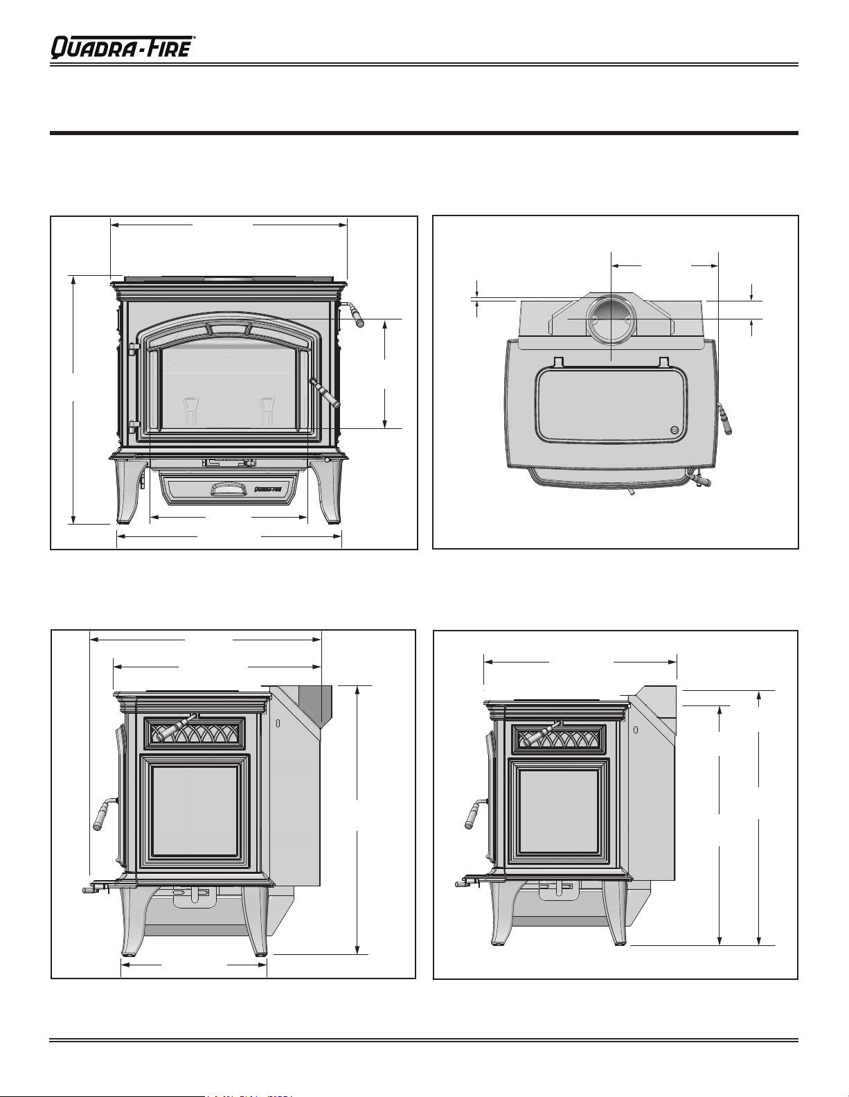
3 Dimensions and Clearances
A. Appliance Dimensions
NOTE:FlueCollarsizeis6inch(152mm)diameter(ID)
Explorer III JP
Figure 7.1 Front View
Figure 7.2 Top View
28-1/4 (718mm)
31-3/8
(797mm)
13
(330mm)
20 (508mm)
30-1/8 (765mm)
15-1/4 (387mm)
2-1/4
(70mm)
3/8
(10mm)
28 (711
3 Dimensions and Clearances
A. Appliance Dimensions
NOTE:FlueCollarsizeis6inch(152mm)diameter(ID)
Explorer III JP
28-1/4 (718mm)
31-3/8
(797mm)
13
(330mm)
20 (508mm)
30-1/8 (765mm)
15-1/4 (387mm)
2-1/4
(70mm)
3/8
(10mm)
3 Dimensions and Clearances
A. Appliance Dimensions
NOTE:FlueCollarsizeis6inch(152mm)diameter(ID)
Explorer III JP
3 Dimensions and Clearances
Explorer III JP
3 Dimensions and Clearances
A. Appliance Dimensions
30-1/8 (765mm)
31-3/8
20 (508mm)
28-1/4 (718mm)
Figure 7.1 Front View
13
(330mm)
NOTE:FlueCollarsizeis6inch(152mm)diameter(ID)
15-1/4 (387mm)
3/8
(10mm)
Figure 7.2 Top View
2-1/4
(70mm)
16-7/8 (429mm)
Figure 7.2 Side View
mm)
25-3/8 (645mm)
31-3/8
(797mm)
24-1/8 (613mm)
Figure 7.4 Side View with horizontal ue
Top of
Flue
Center
of Flue
33-1/8
(841mm)
28-5/8
(727mm)
Page 31 May, 2019 7038-201G
Page 4
EXP-III Wood Burner
5700 Step Top ACC Wood Burner
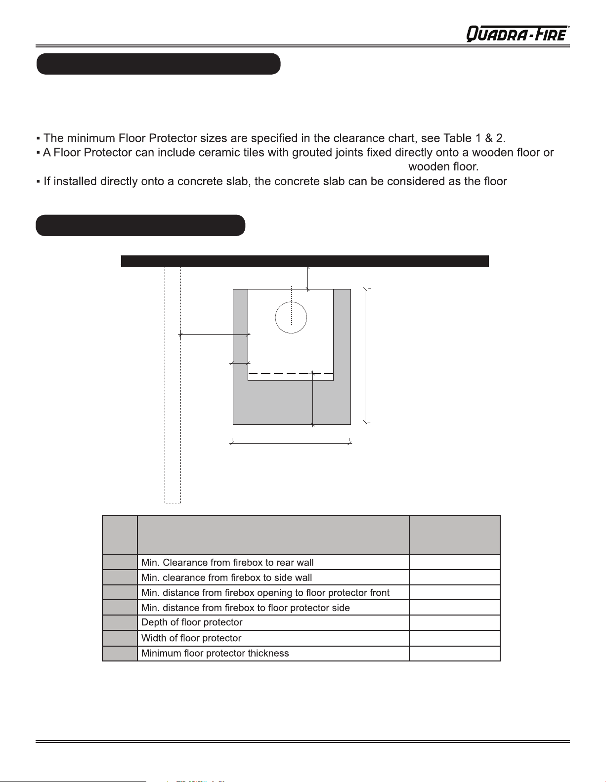
comply with the minimum Floor Protector requirements of
Quadra-fire EXPLORER III does not require an insulating Floor Protector, as they are tested and
AS/NZS 2918:2001.
Note:
a steel panel or any other non combustible material laid directly onto a
protector,but must maintain the minimum measurement listed.
FLOOR PROTECTOR
5700 Step Top ACC Wood Burner
FLOOR PROTECTOR
Quadra-fire EXPLORER III does not require an insulating Floor Protector, as they are tested and
comply with the minimum Floor Protector requirements of
Note:
a steel panel or any other non combustible material laid directly onto a
protector,but must maintain the minimum measurement listed.
PARALLEL POSITIONING
Fig. 3
A
B
AS/NZS 2918:2001.
F
Table 1
A
B
C
D
E
F
G
*Rear wall clearance can be reduced to 150mm when an additional heat sheild is used between active SS & Decromesh.
D
C
G
Drawing not to scale
DESCRIPTION
Au Default
Flue Kit
250mm*
400mm
320mm
84mm
960mm
885mm
6mm
NOTE: HEAT SHIELD REQUIREMENTS FOR HEAT SENSITIVE WALLS
Clearances may be reduced by provision of an appropriately located heat shield refer to
AS/NZS 2198:2001 3.2.3 TABLE 3.1
Page 4 1 May, 20197038-201G
Page 5
5700 Step Top ACC Wood Burner
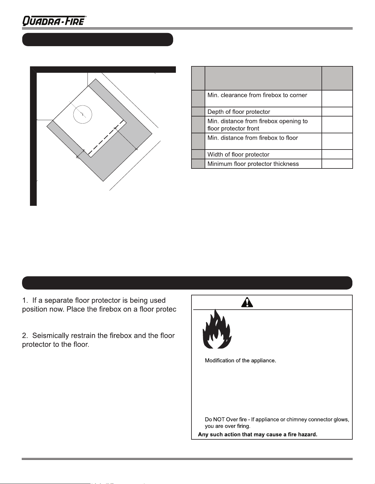
CORNER POSITIONING (45°)
CORNER POSITIONING (45°)
Fig. 4
EXP-III Wood Burner
Table 2
A
B
A
D
C
E
Drawing not to scale
A
walls
B
C
D
protector side
E
DESCRIPTION
AU Default flue kit
Shall be Fitted
175mm
960mm
320mm
84mm
885mm
6mm
FIREBOX INSTALLATION
tor that is at least 6mm thick to suit the minimum
installation clearances. (See Fig 3 or 4).
WARNING
-
Fire Risk.
Hearth & Home Technologies disclaims any
responsibility for, and the warranty will be
voided by, the following actions:
• Installation and use of any damaged appliance.
•
• Installation other than as instructed by Hearth & Home
Technologies.
• Installation and/or use of any component part not approved
by Hearth & Home Technologies.
• Operating appliance without fully assembling all components.
• Operating appliance without legs attached (if supplied with
appliance).
•
Page 51 May, 2019 7038-201G
Page 6
EXP-III Wood Burner
Explorer III Wood Stove
Install Guide
Explorer III Wood Stove
Install Guide
Explorer III Wood Stove
Install Guide
2 Getting Started
Explorer III Wood Stove
Getting Started
A. Design and Installation Considerations
Consideration must be given to:
• Safety
• Convenience
• Trafc ow
• Chimney and chimney connector required
It is a good idea to plan your installation on paper, using
exact measurements for clearances and oor protection,
before actually beginning the installation. If you are not
using an existing chimney, place the appliance where there
will be a clear passage for a factory-built listed chimney
through the ceiling and roof.
We recommend that a qualied building inspector and
your insurance company representative review your plans
before and after installation.
If this appliance is in an area where children may be near
it is recommended that you purchase a decorative barrier
to go in front of the appliance.
children away while it is operating and do not let anyone
operate this appliance unless they are familiar with these
operating instructions.
Remember to always keep
CAUTION
B. Fire Safety
To provide reasonable re safety, the following should be
given serious consideration:
1. Install at least one smoke detector on each oor of
your home to ensure your safety. They should be
located away from the heating appliance and close
to the sleeping areas. Follow the smoke detector
manufacturer’s placement and installation instructions,
and be sure to maintain regularly.
2. A conveniently located Class A re extinguisher to
contend with small res resulting from burning embers.
3. A CO detector should be installed in the room with the
appliance.
4. A practiced evacuation plan, consisting of at least two
escape routes.
5. A plan to deal with a chimney re as follows:
In the event of a chimney re:
a. Evacuate the house immediately
b. Notify re department.
C. Negative Pressure
WARNING
Check building codes prior to installation.
• Installation MUST comply with local, regional, state
and national codes and regulations.
• Consult insurance carrier, local building, re ofcials
or authorities having jurisdiction about restrictions,
installation inspection, and permits.
Asphyxiation Risk.
• Do NOT connect this appliance to a
• Do NOT connect to any air distribution duct
May allow ue gases to enter the house.
NOTICE: HEARTH & HOME TECHNOLOGIES ASSUMES
NO RESPONSIBILITY FOR THE IMPROPER
PERFORMANCE OF THE APPLIANCE SYSTEM
CAUSED BY:
• Inadequate draft due to environmental conditions
• Down drafts
• Tight sealing construction of the structure
• Mechanical exhausting devices
• Over drafting caused by excessive chimney heights
• Ideal performance is with height of chimney between
14-16 feet (4.26-4.88m) measured from the base of
the appliance.
WARNING
chimney ue servicing another appliance.
or system.
Asphyxiation Risk.
• Negative pressure can cause spillage
of combustion fumes, soot and carbon
monoxide.
• Appliance needs to draft properly for
safety.
Negative pressure results from the imbalance of air
available for the appliance to operate properly. It can be
strongest in lower levels of the house.
Causes include:
• Exhaust fans (kitchen, bath, etc.)
• Range hoods
• Combustion air requirements for furnaces, water
appliances and other combustion appliances
• Clothes dryers
• Location of return-air vents to furnace or air
conditioning
• Imbalances of the HVAC air handling system
• Upper level air leaks such as:
- Recessed lighting
- Attic hatch
- Duct leaks
Page 6 1 May, 20197038-201G
Page 7
EXP-III Wood Burner
Explorer III Wood Stove
and benet.
To minimize the effects of negative air pressure:
• Install optional outside air kit with the intake facing
prevailing winds during the heating season
• Ensure adequate outdoor air for all combustion
appliances and exhaust equipment
• Ensure furnace and air conditioning return vents are
not located in the immediate vicinity of the appliance
• Avoid installing the appliance near doors, walkways or
small isolated spaces
• Recessed lighting should be a “sealed can” design
• Attic hatches weather stripped or sealed
• Attic mounted duct work and air handler joints and
seams taped or sealed
• Basement installations should be avoided
WARNING
Fire Risk.
Hearth & Home Technologies disclaims any
responsibility for, and the warranty will be voided
by, the following actions:
• Installation and use of any damaged appliance.
• Modication of the appliance.
• Installation other than as instructed by Hearth &
Home Technologies.
• Installation and/or use of any component part not
approved by Hearth & Home Technologies.
• Operating appliance without fully assembling all
components.
• Operating appliance without legs attached (if supplied
with appliance).
• Do NOT Over re - If appliance or chimney connector
glows, you are over ring.
Any such action that may cause a re hazard.
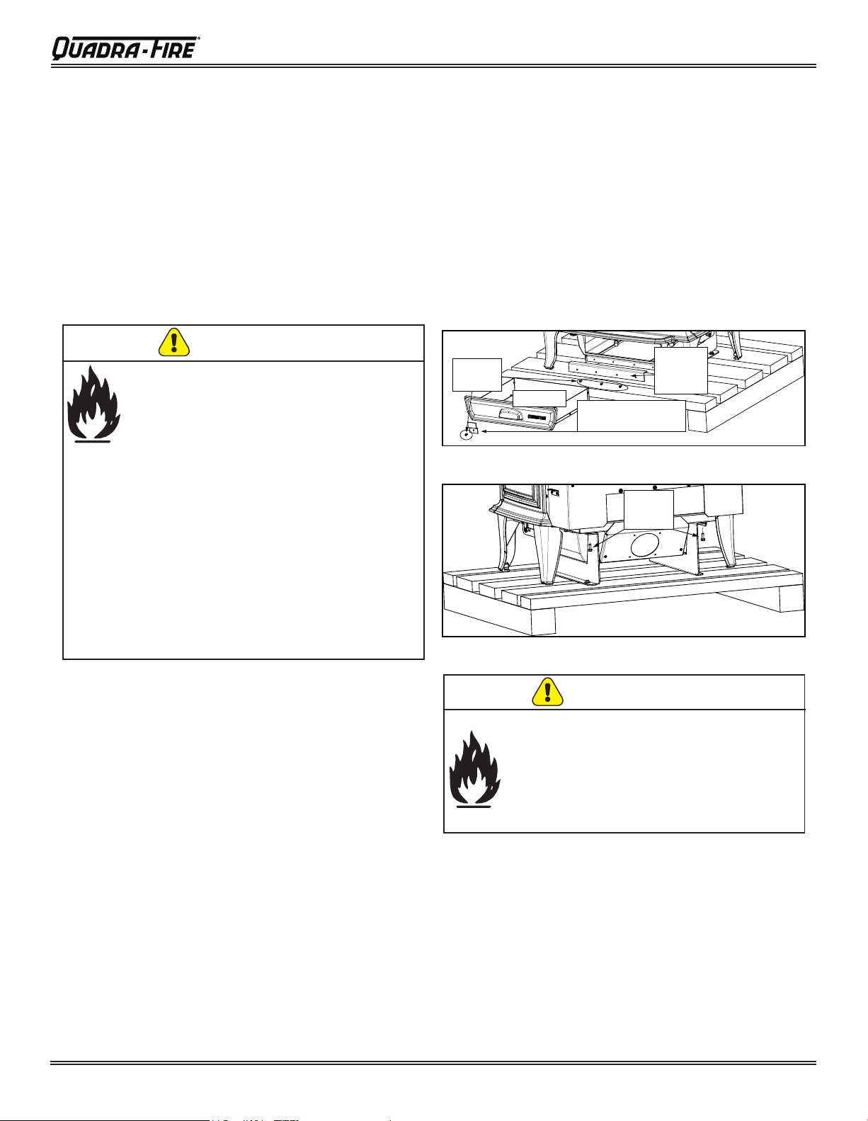
F. Removal of Appliance from Shipping
Materials
1. Remove box and 2x4 structural boards being careful
not to damage product.
2. Using a Phillips screw driver, remove and discard the
4 screws and ash pan retention bracket from front of
appliance (Figure 6.1).
3. Remove ash pan and set aside (Figure 6.1).
4. Remove and discard the pallet attach bracket (Figure
6.1).
5. Using a 3/8 socket or open end wrench, remove two
bolts on back side as shown (Figure 6.2).
6. Slide appliance forward off of pallet support brackets.
7. Replace ash pan (Figure 6.1).
Screws
x4
Figure 6.1
Figure 6.2
Ash pan
Ash Pan
Retention Bracket
Pallet
Attach
Bracket
Bolts
x2
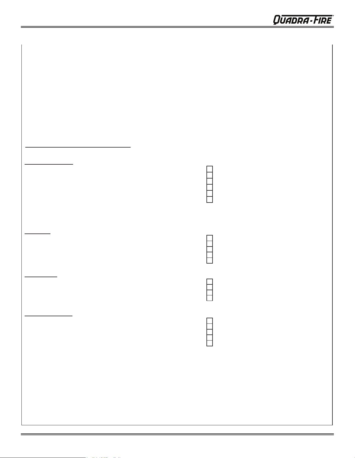
D. Tools And Supplies Needed
Before beginning the installation be sure the following tools
and building supplies are available:
Reciprocating saw
Framing material
Pliers
High temp caulking material
Hammer
Gloves
Phillips screwdriver
Framing square
1/2-3/4 in. length, #6 or #8 self-drilling screws
Flat blade screwdriver
Electric drill and bits
Plumb line
Safety glasses
Level
Tape measure
Misc. screws and nails
7/16 socket or wrench
E. Inspection of Appliance and Components
• Remove appliance and components from packaging
and inspect for damage.
• Report to your dealer any parts damaged in shipment.
• Read all the instructions before starting the
installation. Follow these instructions carefully
during the installation to ensure maximum safety
WARNING
Fire Risk.
Inspect appliance and components for damage.
Damaged parts may impair safe operation.
• Do NOT install damaged components.
• Do NOT install incomplete components.
• Do NOT install substitute components.
Report damaged parts to dealer.
Page 71 May, 2019 7038-201G
Page 8
EXP-III Wood Burner
5700 Step Top ACC Wood Burner
OPERATING INSTRUCTIONS
Air Controls
1. Start-Up Air Control
The Start-Up Air Control has two primary functions. The
rst function is to activate the Automatic Combustion Control
system (ACC). This function is performed by sliding the con-
trol all the way back until it stops at the “HI” indicator on the
label and then pulling forward to the front of the stove until
it stops. This activates the ACC system and opens the front
air channel and allows air to enter the front of the stove for
approximately 25 minutes. The front air channel gradually
shuts down until it is completely closed at the end of the 25
minutes. The re is now controlled by the air supplied by the
Burn Rate Air Control. This function should be performed
each time you reload the stove. Figure 6.1.
2. Burn Rate Air Control
This air supply enters at the upper front of the rebox, near
the top of the glass door. This preheated air supplies the
necessary fresh oxygen to mix with the unburned gases,
helping to create second, third and fourth combustions. This
air is regulated by the Burn Rate Air Control. There are four
settings High, Medium-High, Medium-Low and Low. When
the control is raised all the way up it is on the High setting and
when pushed all the down it is on the Low setting. Figure 6.1.
HIGH
MED
LOW
Burn Rate
Air Control
Start-Up
Air Control
Figure 6.1
Burn Rates
1. Starting a Fire and Reloading
Open both controls fully by raising the Burn Rate Air Control
all the way up until it stops and slide the Start-Up Air Control
back until it stops. After loading the stove with wood and
starting the re, set both controls to the desired setting by
following the burn rate instructions below.
2. High Burn Rate - Maximum Heat
Raise the Burn Rate Air Control all the way up until it stops
(top marker) to a fully open position. Slide the Start-Up Air
Control all the way back until it stops (HI marker) and leave it
there. This setting over-rides the timer system (ACC) so you
must monitor the re closely while in this setting.
3.
Medium-High Burn Rate
Raise the Burn Rate Air Control all the way up until it stops
(top marker) to a fully open position. Slide the Start-Up Air
Control all the way back until it stops (HI marker) and then pull
forward until it stops. This activates the timer system (ACC).
4.
Medium-Low Burn Rate
Raise the Burn Rate Air Control up to the bottom of the middle
marker and stop. Slide the Start-Up Air Control all the way
back until it stops (HI marker) and then pull forward until it
stops. This activates the timer system (ACC).
5. Low Burn Rate
Leave the Burn Rate Air Control at the bottom marker. Slide
the Start-Up Air Control all the way back until it stops (HI
marker) and then pull forward until it stops. This activates
the timer system (ACC).
High (Open)
Low (Closed)
Start-Up Air
Control
Burn Rate
A
ir Control
Front Air Channel
Operated by Timer
Rear Air Channel
Operates independently
from Timer
Timer
Timer Manual
Shut-off
HIGH
LOW
Shown with Side
Shield Removed
Explorer III Wood Stove
ATTENTION INSTALLER:
G. Install Checklist
ATTENTION INSTALLER
Follow this Standard Work Checklist
This standard work checklist is to be used by the installer in conjuction with, not istead of, the instructions contained in this installation manual.
Customer:
Date Installe:
Lot / Address:
Location of Appliance:
Installer:
Dealer / Distributor Phone #:
Serial #:
Model:
_________________________________________________________________________________
______________________________________________________________________________
______________________________________________________________________________
________________________________________________________________________
___________________________________________________________________________________
___________________________________________________________________________________
____________________________________________________________________________________
WARNING! Risk of Fire or Exposion!
Appliance Install
Verified clearances to combustibles.
Appliance is leveled and connector is secured to appliance.
Hearth extension size/height decided.
Outside air kit installed.
Floor protection requirements have been met.
If appliance is connected to a masonry chimney, it should be cleaned and
inspected by a professional. If installed to a factory built metal chimney, the
chimney must be installed according to the manufacturer’s instructions and
clearances.
Chimney
Chimney configuration complies with diagrams.
Chimney installed, locked and secured in place with proper clearance.
Chimney meets recommended height requirements (14-16 feet).
Roof flashing installed and sealed.
Terminations installed and sealed.
Clearances
Combustible materials not installed in non-combustible areas.
Verified all clearances meet installation manual requirements.
Mantels and wall projections comply with installation manual requirements.
Protective hearth strips and hearth extension installed per manual requirements.
Appliance Setup
All packaging and protective materials removed.
Firebrick, baffle and ceramic blanket installed correctly.
All labels have been removed from the door.
All packaging materials are removed from inside/under the appliance.
Manual bag and all of its contents are removed from inside/under the appliance
and given to the party responsible for use and operation.
Hearth & Home Technologies recommends the following:
• Photographing the installation and copying this checklist for your file.
• That this checklist remain visible at all times on the appliance until the installtion is complete.
Comments: Further description of the issues, who is responsible (Installer/Builder/Other Trades, etc.) and corrective action needed:
Comments communicated to party responsible ____________________________ by _____________________ on ___________
Page 8 1 May, 20197038-201G
___________________________________________________________________
Failure to install appliance according to these instruction can lead to a fire or explosion.
YES IF NO, WHY?
______________________________________
______________________________________
______________________________________
______________________________________
______________________________________
______________________________________
(Builder / Gen. Contractor) (Installer) (Date)
______________________________________
______________________________________
______________________________________
______________________________________
______________________________________
______________________________________
______________________________________
______________________________________
______________________________________
______________________________________
______________________________________
______________________________________
______________________________________
______________________________________
Page 9

EXP-III Wood Burner
5700 Step Top ACC Wood Burner
the timer system (ACC).
A
Explorer III Wood Stove
Figure 11.1
Burn Rate Control
ACC Control
Figure 11.2
E. Air Controls
1. Burn Rate Air Control
This air supply enters at the upper front of the rebox,
near the top of the glass door. This preheated air
supplies the necessary fresh oxygen to mix with the
unburned gases, helping to create second, third and
fourth combustions. This air is regulated by the Burn
Rate Air Control. When the control is moved all the way
to the left it is on the High setting and when moved
all the way to the right it is on the Low setting (Figure
11.1).
2. Start-Up Air Control
The Start-Up Air Control function is to activate the
Automatic Combustion Control system (ACC). This
function is performed by pushing the control all the way
back until it stops and then pulling forward to the front
of the appliance until it stops. This activates the ACC
system and opens the front air channel and allows air
to enter the front of the appliance for approximately
25 minutes. The front air channel gradually shuts
down until it is completely closed at the end of the 25
minutes. The re is now controlled by the air supplied
by the Burn Rate Air Control. This function should be
performed each time you reload the appliance. Start up
air can be locked open for High burn setting if desired;
see page 10 for instructions (Figure 11.1).
3. Manual Timer Over-Ride
If you need to shut the ACC system off before it shuts
itself off after 25 minutes (i.e. over re situation), reach
down to the bottom right and pull the lever toward you
(Figure 11.2).
D. Automatic Combustion Control (ACC)
Typically, when you build a re, you open the air controls
fully and monitor the re to prevent it from going into an
over re situation and/or burning your wood up too quickly
before you shut down the air controls to the desired burn
rate. With the Automatic Combustion Control (ACC)
system, you do not have to continually monitor the re.
Once you set the ACC system it will control the re for you.
Follow the instructions below to learn how to operate your
appliance with ease.
2. Second Stage
The next stage of burning, the secondary stage, is the
period when the wood gives off ammable gases which
burn above the fuel with bright ames. During this stage of
burning it is very important that the ames be maintained
and not allowed to go out. This will ensure the cleanest
possible re. If the ames tend to go out, it is set too low for
your burning conditions. The air control located at the upper
right hand corner is used to adjust for burn rates. This is
called the Burn Rate Air Control (Figure 11.1).
3. Final Stage
The nal stage of burning is the charcoal stage. This occurs
when the ammable gases have been mostly burned and
only charcoal remains. This is a naturally clean portion of
the burn. The coals burn with hot blue ames.
It is very important to reload your appliance while enough
lively hot coals remain in order to provide the amount of
heat needed to dry and rekindle the next load of wood. It
is best to open the Burn Rate Air and Start-Up Air Controls
before reloading. This livens up the coal bed and reduces
excessive emissions (opacity/smoke). Open door slowly so
that ash or smoke does not exit appliance through opening.
You should also break up any large chunks and distribute
the coals so that the new wood is laid on hot coals.
Air quality is important to all of us, and if we choose to
use wood to heat our homes we should do so responsibly.
To do this we need to learn to burn our appliances in the
cleanest way possible. Doing this will allow us to continue
using our wood appliances for many years to come.
Injury Risk.
• Gloves recommended
CAUTION
Explorer III Wood Stove
Figure 11.2
This air supply enters at the upper front of the rebox,
near the top of the glass door. This preheated air
supplies the necessary fresh oxygen to mix with the
unburned gases, helping to create second, third and
fourth combustions. This air is regulated by the Burn
Rate Air Control. When the control is moved all the way
to the left it is on the High setting and when moved
all the way to the right it is on the Low setting (Figure
11.1).
The Start-Up Air Control function is to activate the
Automatic Combustion Control system (ACC). This
function is performed by pushing the control all the way
back until it stops and then pulling forward to the front
of the appliance until it stops. This activates the ACC
system and opens the front air channel and allows air
to enter the front of the appliance for approximately
25 minutes. The front air channel gradually shuts
down until it is completely closed at the end of the 25
minutes. The re is now controlled by the air supplied
by the Burn Rate Air Control. This function should be
performed each time you reload the appliance. Start up
air can be locked open for High burn setting if desired;
see page 10 for instructions (Figure 11.1).
If you need to shut the ACC system off before it shuts
itself off after 25 minutes (i.e. over re situation), reach
down to the bottom right and pull the lever toward you
(Figure 11.2).
Injury Risk.
• Gloves recommended
CAUTION
OPERATING INSTRUCTIONS
Air Controls
1. Start-Up Air Control
The Start-Up Air Control has two primary functions. The
rst function is to activate the Automatic Combustion Control
system (ACC). This function is performed by sliding the control all the way back until it stops at the “HI” indicator on the
label and then pulling forward to the front of the stove until
it stops. This activates the ACC system and opens the front
air channel and allows air to enter the front of the stove for
approximately 25 minutes. The front air channel gradually
shuts down until it is completely closed at the end of the 25
minutes. The re is now controlled by the air supplied by the
Burn Rate Air Control. This function should be performed
each time you reload the stove. Figure 6.1.
2. Burn Rate Air Control
This air supply enters at the upper front of the rebox, near
the top of the glass door. This preheated air supplies the
necessary fresh oxygen to mix with the unburned gases,
helping to create second, third and fourth combustions. This
air is regulated by the Burn Rate Air Control. There are four
settings High, Medium-High, Medium-Low and Low. When
the control is raised all the way up it is on the High setting and
when pushed all the down it is on the Low setting. Figure 6.1.
Burn Rates
1. Starting a Fire and Reloading
Open both controls fully by raising the Burn Rate Air Control
all the way up until it stops and slide the Start-Up Air Control
back until it stops. After loading the stove with wood and
starting the re, set both controls to the desired setting by
following the burn rate instructions below.
2. High Burn Rate - Maximum Heat
Raise the Burn Rate Air Control all the way up until it stops
(top marker) to a fully open position. Slide the Start-Up Air
Control all the way back until it stops (HI marker) and leave it
there. This setting over-rides the timer system (ACC) so you
must monitor the re closely while in this setting.
3.
Medium-High Burn Rate
Raise the Burn Rate Air Control all the way up until it stops
(top marker) to a fully open position. Slide the Start-Up Air
Control all the way back until it stops (HI marker) and then pull
forward until it stops. This activates the timer system (ACC).
Medium-Low Burn Rate
4.
Raise the Burn Rate Air Control up to the bottom of the middle
marker and stop. Slide the Start-Up Air Control all the way
back until it stops (HI marker) and then pull forward until it
stops. This activates the timer system (ACC).
5. Low Burn Rate
Leave the Burn Rate Air Control at the bottom marker. Slide
the Start-Up Air Control all the way back until it stops (HI
marker) and then pull forward until it stops. This activates
Burn Rate
Air Control
Figuer 9.1
Start-Up
Air Control
Figure 6.1
HIGH
Shown with Side
Shield Removed
LOW
HIGH
MED
LOW
Low (Closed)
Figuer 9.2
Burn Rate
ir Control
Start-Up Air
Control
Front Air Channel
Operated by Timer
Operates independently
High (Open)
Rear Air Channel
from Timer
Timer
Timer Manual
Shut-off
Page 91 May, 2019 7038-201G
Page 10

EXP-III Wood Burner
5700 Step Top ACC Wood Burner
GENERAL INSTRUCTIONS FOR FLUE SYSTEM
▪ Flue pipe installed crimp/narrow end down
▪ Outer casings installed crimped/narrow end up. (Critical when exposed above the roof)
▪ Inner casings - direction not critical
▪ Flue pipes - seal all joints including rebox spigot.
- x with a minimum of 3 stainless steel rivets
▪ Flue pipe spacers - afx to ue pipe
▪ Flue system termination point - Refer to AS/NZS 2918:2001 4.9.1.
▪ Flue pipe shall extend not less than 4.6m above top of the oor protector as per
AS/NZS 2918:2001 4.9.1(a)
▪ Façade or chase systems - same rule applies as above.
▪ Roof penetration and ashing method refer to NZ Building Code E2.(From 01/07/05)
Note: These instructions apply to 150mm diameter ue pipe systems as tested to
AS/NZS 2918:2001
1. Either locate the appliance in position or by measuring at the ceiling mark the ue pipe centre position.
Check that the outer casing is unobstructed through the attic space or roof area.
2. Spike the centre with a nail. Transfer this position to the next surface above. Plumb bob/laser.
3. Cut out the ceiling penetration hole – square or rectangle – short axis equals outer casing diameter
plus 50mm, long axis as required. See Table 5 . Perform the same at the roof penetration.
4. Frame out the hole with minimum 75 x 50 timber or as required for roong material. Minimum
requirement at roof penetration see NZ Building Code E2 Acceptable Solution (from 01/07/05).
5. Install the outer casing so that :-
(i) lower end is ush with the underside of the ceiling material and
(ii) with the addition of metal “L” brackets, afx to the outer casing at 90 degrees secure the outer
casing centrally to the ceiling and roof nogs. Alternatively substitute the “L” brackets for 25mm thick
non heat sensitive packers. Secure the outer casing through the packers with horizontal xings to
the nogs. Refer to the General Instruction for termination height. The option of outer casing slips to
be taken into account.
6. Flash the outer casing to the roof material with the appropriate approved ashing.
7. If using an outer/inner casing combination, now install the inner casing ensuring it extends a minimum
200mm above the high side of the roof penetration. If not using a combination see ‘11’ below.
8. Refer to Firebox Installation, points 1 & 2.
9. Prepare the ceiling plate and place upside down over the ue spigot.
10. Install the ue pipes by preferred method – either up or down the outer casing. Afx each length
per the notes in General Instructions (above). Extend the ue pipe above the outer
casing to suit the casing cover/cowl assembly.
11. If the inner casing has not been installed, install now. Refer to 7 above for minimum height.
12. Install the cowl assembly, i.e. Top spacer, casing cover and cowl.
13. Position and secure the ceiling plate with the screws and spacers.
14. Wipe the ue pipe to remove nger marks.
15. Refer to Firebox Installation, point 3.
16. If ue offset is required, refer to AS/NZS 2918:2001 4.1
Page 10 1 May, 20197038-201G
Page 11

5700 Step Top ACC Wood Burner
C
L
Drawing not to scale
12
Tested flue systems, as per AS/NZS 2918:2001
Fig. 5
ADD Cowl
Casing Cover
Spider Bracket
oversized casing cover
is necessary
minimum 25mm gap
between flue pipe casing &
combustible material
Non combustible material
Hebel block or 12mm
Promina board or similar
under the flashing
25 25
Approved Flashing
Roof Line
Inner Casing 200mm
above roof line
Outer Casing
Inner Casing
25
Internal Swage
25 25
12.5
V
ented
C
eiling Plate
Flue Pipe
C
L
C L
Quadra-fire 5700
Floor
The flue crimp must be cut so the swage
(half-moon bulge after the crimp) fits
tightly into the spigot.
FLUE PENETRATION
EXP-III Wood Burner
Page 111 May, 2019 7038-201G
Page 12

EXP-III Wood Burner
5700 Step Top ACC Wood Burner
FLUE PENETRATION
Un-tested flue systems, as per AS/NZS 2918:2001, 4.6.3(b)
1.QF.1F
Fig. 6
AS/NZS2918:2001
Un-tested flue with sloped ceiling
penetration greater than 30° from
horizontal
A = 25mm
4.6.3(b)
Fig 4.6 = downward distance of
casing and 3 x ø flue distance of
the ceiling plate
Batten
150
ADD Cowl
A
A
Casing Cover
Spider Bracket
Approved Flashing
Ceiling Plate
Fig. 7
Ceiling
AS/NZS2918:2001
Un-tested flue with sloped ceiling
penetration greater than 30° from
horizontal
A = 25mm
4.6.3(b)
Fig 4.6 = 3 x ø flue from active flue
to heat sensitive surface
Batten
3 x Ø flue pipe
flue pipe
Ø
A
ADD Cowl
Casing Cover
Spider Bracket
Approved Flashing
A
Ceiling Plate
Ceiling
flue pipe
Ø
Page 12 1 May, 20197038-201G
Page 13

EXP-III Wood Burner
5700 Step Top ACC Wood Burner
GENERAL INSTRUCTIONS FOR FLUE SYSTEM
1. Unpack the Flue Mounted Shield, detach the three brackets and familarize yourself with the illustrations.
it meets the outer shield (refer sketch). Cut along the full length of the Flue Mounted Shield on both
4. Fit the top bracket to the Flue Mounted Shield as illustrated ensuring the rear mid section of the
f both the lower outer legs from the
.
Two tabs are provided and if folded back at 90 degrees the bracket and Flue Mounted Shield will
mount lower onto the appliance.
The Flue Mounted Shield then locates into the two notches provided n bracket “5B” as illustated.
grill to be removed.
7. Using the pre-punched holes in the two tabs provided on the top bracket as guides, drill into the
MINIMUM HEIGHT OF FLUE SYSTEM EXIT
Fig. 8
6000
3000
or
less
600
More than
min.
3000
3000
increase from 1000mm
minimum until clear within
increase as
until nothing
6000mm of flue
Any nearby
necessary
within
top
structure
3000mm of flue top
Page 131 May, 2019 7038-201G
Page 14

EXP-III Wood Burner
5700 Step Top ACC Wood Burner
HAZARDOUS.
AS/NZS 2918:2001 General Notes
WARNING: THE APPLIANCE AND FLUE SYSTEM SHALL BE INSTALLED IN ACCORDANCE
WITH AS/NZS 2918 AND THE APPROPRIATE REQUIREMENTS OF THE RELEVANT BUILDING
CODE OR CODES.
WARNING: APPLIANCES INSTALLED IN ACCORDANCE WITH THIS STANDARD SHALL
COMPLY WITH THE REQUIREMENTS OF AS/NZS 4013 WHERE REQUIRED BY THE REGULATORY AUTHORITY, I.E. THE APPLIANCE SHALL BE IDENTIFIABLE BY A COMPLIANCE PLATE
WITH THE MARKING ‘TESTED TO AS/NZS 4013’.
ANY MODIFICATION OF THE APPLIANCE THAT HAS NOT BEEN APPROVED IN WRITING BY
THE TESTING AUTHORITY IS CONSIDERED TO BE IN BREACH OF THE APPROVAL GRANTED
FOR COMPLIANCE WITH AS/NZS 4013.
CAUTION: MIXING OF APPLIANCE OR FLUE SYSTEM COMPONENTS FROM DIFFERENT
SOURCES OR MODIFYING THE DIMENSIONAL SPECIFICATION OF COMPONENTS MAY
RESULT IN HAZARDOUS CONDITIONS. WHERE SUCH ACTION IS CONSIDERED, THE MANUFACTURER SHOULD BE CONSULTED IN THE FIRST INSTANCE.
CAUTION: THIS APPLIANCE SHOULD NOT BE OPERATED WITH CRACKED AND BROKEN
COMPONENTS, e.g. GLASS PANELS OR CERAMIC TILES, MAY RENDER THE INSTALLATION
UNSAFE.
WARNING: ANY MODIFICATION OF THE APPLIANCE THAT HAS NOT BEEN APPROVED IN
WRITING BY THE TESTING AUTHORITY IS CONSIDERED AS BREACHING AS/NZS 4013.
WARNING: DO NOT USE FLAMMABLE LIQUIDS OR AEROSOLS TO START OR REKINDLE THE FIRE.
WARNING: DO NOT USE FLAMMABLE LIQUIDS OR AEROSOLS IN THE VICINITY OF THIS
APPLIANCE WHEN ITS OPERATING.
WARNING: DO NOT STORE FUEL WITHIN HEATER INSTALLATION CLEARANCES.
WARNING: OPEN AIR CONTROLS AND DAMPER WHEN FITTED BEFORE OPENING FIRING
DOOR.
WARNING: FOR OPTIMUM PERFORMANCE FUEL MUST BE LOADED SO THE LOGS LAY
“FRONT TO REAR” IN PREFERENCE TO LAYING ACROSS THE WIDTH OF THE FIREBOX.
SPACES SHOULD BE LEFT BETWEEN THE LOGS TO ENABLE OXYGEN TO GET TO AS MUCH
OF THE SURFACE OF THE FUEL AS POSSIBLE.
CAUTION: THIS APPLIANCE SHOULD BE MAINTAINED AND OPERATED AT ALL TIMES IN
ACCORDANCE WITH THESE INSTRUCTIONS.
CAUTION: THE USE OF SOME TYPES OF PRESERVATIVE-TREATED WOOD AS A FUEL CAN BE
Page 14 1 May, 20197038-201G
Page 15

5700 Step Top ACC Wood Burner
Service And Maintenance Log
Date of Service Performed By Description of Service
EXP-III Wood Burner
Page 151 May, 2019 7038-201G
Page 16

EXP-III Wood Burner
5700 Step Top ACC Wood Burner
AUSTRALIAN WARRANTY INFORMATION
Hearth & Home Technologies Inc (HHT)
1445 N. Highway | Colville, WA 99114 | (509-684-3745)
HHT extends the following manufacturer’s warranty for HHT gas, wood, pellet, coal and electric hearth appliances that are purchased
from an HHT authorized dealer.
HHT warrants to the original owner of the HHT appliance at the site of installation, and to any transferee taking ownership of the appliance
at the site of installation within two years following the date of original purchase, that the HHT appliance will be free from defects in
materials and workmanship at the time of manufacture.
After installation, if covered components manufactured by HHT are found to be defective in materials or workmanship during the applicable
warranty period, HHT will, at its option, repair or replace the covered components. HHT, at its own discretion, may fully discharge all of
its obligations under this manufacturer’s warranty by replacing the product itself or refunding the veri ed purchase price of the product
itself. The maximum amount recoverable under this warranty is limited to the purchase price of the product. This warranty is subject to
conditions, exclusions and limitations as described below.
Warranty coverage begins on the date of original purchase. In the case of new home construction, coverage under this manufacturer’s
warranty begins on the date of rst occupancy of the dwelling or six months after the sale of the product by an independent, authorized
HHT dealer/ distributor, whichever occurs earlier. The warranty period for this manufacturer’s warranty shall commence no later than 24
months following the date of product shipment from HHT, regardless of the installation or occupancy date. The manufacturer’s warranty
period for parts and labor for covered components is produced in the following table.
The term “Limited Lifetime” in the table below is de ned as: 20 years from the beginning date of warranty coverage for gas appliances,
and 10 years from the beginning date of warranty coverage for wood, pellet and coal appliances. These time periods re ect the minimum
expected useful lives of the designated components under normal operating conditions.
Warranty Period Hearth and Home Technologies Manufactured Appliances and Venting
Parts Labor Gas Wood Pellet
1 Year X X X X X X X
X X X
2 years
3 years X Firepots and Burnpots
5 years 1 year X X Castings and baf es
7 years 3 years X X X
10
years
1 year X
X X X X X
X Molded refractory panels
EPA
Wood
Coal Electric Venting
Components Covered
All parts and material
except as covered by
Conditions, Exclusions,
and Limitations listed
Igniters, electronic
components, and glass
Factory-installed blowers
Manifold tubes,
HHT chimney and
termination
Burners, logs and
refractory
Limited
Lifetime
3 years X X X X X
90 Days X X X X X X X
Page 16 1 May, 20197038-201G
Firebox and heat
exchanger
All replacement parts
beyond warranty period
Page 17

EXP-III Wood Burner
5700 Step Top ACC Wood Burner
OTHER RIGHTS
The HHT manufacturer’s warranty is in addition to other rights and remedies that you may have under Australian
law.
Our goods come with guarantees that cannot be excluded under the Australian Consumer Law. You are entitled
to a replacement or refund for a major failure and for compensation for any other reasonably foreseeable loss or
damage. You are also entitled to have the goods repaired or replaced if the goods fail to be of acceptable quality
and the failure does not amount to a major failure.
WARRANTY CONDITIONS AND EXCLUSIONS:
• The HHT manufacturer’s warranty only covers HHT appliances that are purchased through an HHT authorized dealer or distributor.
A list of HHT authorized dealers is available on the HHT branded websites.
• This warranty is only valid while the HHT appliance remains at the site of original installation.
WARRANTY EXCLUSIONS:
This HHT manufacturer’s warranty does not cover the following:
• Changes in surface nishes as a result of normal use. As a heating appliance, some changes in color of interior and exterior surface
nishes may occur. This is not a aw and is not covered under warranty.
• Damage to printed, plated, or enamelled surfaces caused by ngerprints, accidents, misuse, scratches, melted items, or other
external sources and residues left on the plated surfaces from the use of abrasive cleaners or polishes.
• Repair or replacement of parts that are subject to normal wear and tear during the warranty period. These parts include: paint, wood,
pellet and coal gaskets, rebricks, grates, ame guides, light bulbs, batteries and the discoloration of glass.
• Minor expansion, contraction, or movement of certain parts causing noise. These conditions are normal and complaints related to this
noise are not covered by this warranty.
• Damages resulting from: (1) failure to install, operate, or maintain the appliance in accordance with the installation instructions,
operating instructions, and listing agent identi cation label furnished with the appliance; (2) failure to install the appliance in
accordance with local building codes; (3) shipping or improper handling; (4) improper operation, abuse, misuse, continued operation
with damaged, corroded or failed components, accident, or improperly/incorrectly performed repairs; (5) environmental conditions,
inadequate ventilation, negative pressure, or drafting caused by tightly sealed constructions, insuf cient make-up air supply, or
handling devices such as exhaust fans or forced air furnaces or other such causes; (6) use of fuels other than those speci ed in the
operating instructions; (7) installation or use of components not supplied with the appliance or any other components not expressly
authorized and approved by HHT (8) modi cation of the appliance not expressly authorized and approved by HHT in writing; and/or
(9) interruptions or uctuations of electrical power supply to the appliance.
• Non HHT venting components, hearth components or other accessories used in conjunction with the appliance.
• Any part of a pre-existing replace system in which an insert or a decorative gas appliance is installed.
• Removal, installation, reinstallation, set up or any other costs associated with a claim including travel and shipping charges for parts.
• HHT’s obligation under this warranty does not extend to the appliance’s capability to heat the desired space. Information is provided
to assist the consumer and the dealer in selecting the proper appliance for the application. Consideration must be given to appliance
location and con guration, environmental conditions, insulation and air tightness of the structure.
This warranty is void if:
• The appliance has been over- red or operated in atmospheres contaminated by chlorine, uorine, or other damaging chemicals.
Over- ring can be identi ed by, but not limited to, warped plates or tubes, rust coloured cast iron, bubbling, cracking and discoloration
of steel or enamel nishes.
• The appliance is subjected to prolonged periods of dampness or condensation.
• There is any damage to the appliance or other components due to water or weather damage which is the result of, but not limited to,
improper chimney or venting installation.
HOW TO CLAIM
• To make a claim against this warranty, contact your local distributor during regular business hours. See addresses below for a dealer
nearest you. (Vic) Pty Ltd ACN 005 872 159 (Jetmaster).
• Additional service fees may apply if you are seeking warranty service from a dealer other than the dealer from whom you originally
purchased the product.
• Check with Jetmaster in advance for any costs to you when arranging a warranty call. Travel and shipping charges for parts are not
covered by this manufacturers’ warranty.
• HHT and Jetmaster will assess your claim. HHT or Jetmaster may need to inspect the product as part of the assessment of your
claim. If the product requires inspection, HHT or Jetmaster will discuss with you the best way for this to occur.
• To make a claim under this manufacturer’s warranty, you must be able to prove when you purchased the product. The easiest way to
do this is through your original proof of purchase, for example your invoice or receipt. However, if you do not have your original proof
of purchase HHT or Jetmaster may accept other evidence of the date of purchase.
Local Distributors:
Melbourne Jetmaster 44 Swan Street Richmond 3121 (03) 9429-5573
Perth Fireplace Corner 277 Lord Street East Perth 6000 (08) 9228-2600
Sydney Jetmaster 10 Martin Avenue Arncliff 2205 (02) 9597-7222
Page 171 May, 2019 7038-201G
Page 18

EXP-III Wood Burner
R
Service Parts
Explorer III
Wood Stove
Color SKU Mfg. Dates
Matte Black EXPLR-III-MBK 02/15-
Porcelain Black EXPLR-III-PBK 02/15-
Porcelain Dark Blue EXPLR-III-PDB 02/15-
Porcelain Frost EXPLR-III-PFT 02/15-
Porcelain Mahogany EXPLR-III-PMH 02/15-
6
7
8
9
1
2
5
30
Beginning Manufacturing Date: Feb 2015
Ending Manufacturing Date: Active
38
3
4
37
36
35
34
33
32
11
10
12
19
20
17
18
22
21
16
23
14
13
15
24
25
28
31
29
27
26
Part number list on following page.
Page 18 1 May, 20197038-201G
08/18
Page 19

EXP-III Wood Burner
R
Service Parts
Beginning Manufacturing Date: Feb 2015
Ending Manufacturing Date: Active
IMPORTANT: THIS IS DATED INFORMATION. Parts must be ordered from a dealer or
distributor.
model number and serial number when requesting service parts from your dealer or distributor.
ITEM DESCRIPTION COMMENTS PART NUMBER
10 Rear Brick Retainer SRV7060-133
11 Side Brick Retainer Qty 2 req SRV7060-193
12 Brick Assembly SRV7060-017
13 Ashlip
Hearth and Home Technologies does not sell directly to consumers. Provide
1 Shroud Assembly SRV7060-009
2 Flue Collar SRV7061-201
3 Outside Air Chamber SRV7061-014
4 Convection Mount Plates Qty 2 req SRV7060-197
5 Flue Transition SRV29138
6 Top Load Handle Assembly SRV7060-055
Top Load Handle Receiver SRV7060-257
7 Lid Assembly SRV7060-006
Gasket, Rope 1/4” 834-1460 Y
Matte Black 7060-101MBK
Porcelain Mahogany 7060-101PMH
8 Top
Gasket, 7/16” 844-3980 Y
9 Side Left
Porcelain Dark Blue 7060-101PDB
Porcelain Black 7060-101PBK
Porcelain Frost 7060-101PFT
Matte Black 7060-034MBK
Porcelain Mahogany 7060-034PMH
Porcelain Dark Blue 7060-034PDB
Porcelain Black 7060-034PBK
Porcelain Frost 7060-034PFT
Matte Black 7060-113MBK
Porcelain Mahogany 7060-113PMH
Porcelain Dark Blue 7060-113PDB
Porcelain Black 7060-113PBK
Porcelain Frost 7060-113PFT
Explorer III
Stocked
at Depot
Additional service part numbers appear on following page.
Page 191 May, 2019 7038-201G
Page 20

EXP-III Wood Burner
R
Service Parts
Beginning Manufacturing Date: Feb 2015
Ending Manufacturing Date: Active
IMPORTANT: THIS IS DATED INFORMATION. Parts must be ordered from a dealer or distributor.
Hearth and Home Technologies does not sell directly to consumers. Provide model number
and serial number when requesting service parts from your dealer or distributor.
ITEM DESCRIPTION COMMENTS PART NUMBER
#14 Door Assembly
Explorer III
Stocked
at Depot
14.1
14.9
14.8
14.2
14.7
14.10
14.3
14.6
14.5
14.4
Matte Black 7060-028MBK
Porcelain Mahogany 7060-028PMH
14 Door Assembly
Gasket, Rope 1/4” 834-1460 Y
14.1 Glass Retainers SRV7063-166 Y
14.2 Glass Assembly SRV7060-029
14.3 Door
14.4 Door Handle Assembly SRV7060-031 Y
14.5 Fiber Handle SRV7060-212 Y
14.6 Door Handle SRV7063-137
14.7 Washer, Sae, 3/8 (3 Ea) Pkg of 3 832-0990 Y
14.8 Cam Latch SRV430-1141
14.9 Nut, 2Wy Side Lock Jam 3 Pkg of 24 226-0100/24 Y
14.10 Key, Cam Latch SRV430-1151
Additional service part numbers appear on following page.
Porcelain Dark Blue 7060-028PDB
Porcelain Black 7060-028PBK
Porcelain Frost 7060-028PFT
Matte Black 7060-204MBK
Porcelain Mahogany 7060-204PMH
Porcelain Dark Blue 7060-204PDB
Porcelain Black 7060-204PBK
Porcelain Frost 7060-204PFT
Page 20 1 May, 20197038-201G
Page 21

EXP-III Wood Burner
R
Service Parts
Beginning Manufacturing Date: Feb 2015
Ending Manufacturing Date: Active
IMPORTANT: THIS IS DATED INFORMATION. Parts must be ordered from a dealer or
distributor.
model number and serial number when requesting service parts from your dealer or distributor.
ITEM DESCRIPTION COMMENTS PART NUMBER
15 Front
16 Andirons 2 pcs SRV7061-020
17 Front Air Channel SRV7060-132
18 ARS Channel SRV7061-184
19 ARS Access Cover SRV7038-196
20 ARS Latch Assembly
21 Burn Rate Indicator SRV7061-191
22 Burn Rate Control SRV7060-027
23 Access Panel SRV7061-185
24 ARS Door Assembly
25 Gasket, ARS SRV7033-296 Y
26 Ashpan SRV7060-023
27 ARS Box SRV7060-005
28 Timer Door SRV7060-040
29 Timer Assembly SRV7060-036
30 Secondary Channels Qty 2 req SRV7060-208
Hearth and Home Technologies does not sell directly to consumers. Provide
Matte Black 7060-103MBK
Porcelain Mahogany 7060-103PMH
Porcelain Dark Blue 7060-103PDB
Porcelain Black 7060-103PBK
Porcelain Frost 7060-103PFT
Gasket, 7/16” 844-3980 Y
Pre 00706300534 SRV7061-023
Post 00706300535 SRV7060-050
Handle, Fiber SRV7060-202
Pre 00706300534 SRV7061-021
Post 00706300535 SRV7060-048
Handle Cover, Access SRV7038-197
Knob SRV7000-343
Timer (Only) Replacement Assembly SRV480-1940
Explorer III
Stocked
at Depot
Additional service part numbers appear on following page.
Page 211 May, 2019 7038-201G
Page 22

EXP-III Wood Burner
Additional service part numbers appear on following page.
R
Service Parts
Beginning Manufacturing Date: Feb 2015
Ending Manufacturing Date: Active
IMPORTANT: THIS IS DATED INFORMATION. Parts must be ordered from a dealer or
distributor.
model number and serial number when requesting service parts from your dealer or distributor.
ITEM DESCRIPTION COMMENTS PART NUMBER
Hearth and Home Technologies does not sell directly to consumers. Provide
#30 Baf e Assembly
31.1
31.2
31.3
31.4
Explorer III
Stocked
at Depot
31.5
31.7
31.8
31.6
31 Baf e Assembly SRV7060-025
31.1 Baf e Cover Top ( Includes Insulation Blanket ) SRV7060-238
31.2 Baf e Blanket SRV7060-233 Y
31.3 Baf e Plate SRV7060-205
31.4 Baf e Board SRV7060-148 Y
31.5 Secondary Tubes Qty 3 req SRV7060-226 Y
31.6 Baf e Cover Plates SRV7060-206
31.7 Baf e Linkage SRV7060-044
31.8 Baf e Door Handle SRV7060-217
Matte Black 7060-033MBK
Porcelain Mahogany 7060-033PMH
32 Side Right
33 Manifold Gaskets Qty 2 req SRV7060-221
34 Air Supply Chambers Right and Left SRV7060-189
35 Pivot Tube Assemblies Qty 2 req SRV7060-018
36 Rear Baf e Plate SRV7060-201
37 Baf e Board Rear SRV7060-213
38 Top Load Handle Hanger SRV7060-262
Porcelain Dark Blue 7060-033PDB
Porcelain Black 7060-033PBK
Porcelain Frost 7060-033PFT
Page 22 1 May, 20197038-201G
Page 23

EXP-III Wood Burner
R
Service Parts
Beginning Manufacturing Date: Feb 2015
Ending Manufacturing Date: Active
IMPORTANT: THIS IS DATED INFORMATION. Parts must be ordered from a dealer or
distributor.
model number and serial number when requesting service parts from your dealer or distributor.
ITEM DESCRIPTION COMMENTS PART NUMBER
Hearth and Home Technologies does not sell directly to consumers. Provide
Matte Black SRV7060-038
Porcelain Mahogany SRV7060-039
Component Pack
Leveling Assembly 7000-000
Paint Touch-Up
Porcelain Dark Blue SRV7060-041
Porcelain Black SRV7060-042
Porcelain Frost SRV7060-043
Matte Black 812-0910
Porcelain Mahogany 855-1450
Porcelain Dark Blue 1-00-0020
Porcelain Black 1-00-0022
Porcelain Frost 1-00-0021
Explorer III
Stocked
at Depot
ACCESSORIES
Blower Assembly BK-ACC
Blower Control Box W/Switch SRV7000-194
Component Pack 7033-051
Magnet Round SRV7000-140
Snap Disc Bracket Assembly 7033-036
Snap Disc, # 1, Convection Blower SRV230-0470
Speed Control Only (Rheostat) 842-0370
Wire Harness (Blower) 7033-262
Blower, Convection Blower Only 812-4900 Y
Outside Air Kit, Floor & Rear OAK-ACC
Outside Air Collar Assembly 7033-039
Outside Air Shield SRV33271
Firescreen SCR-7060
FASTENERS
Avk Rivnut Repair Kit - 1/4-20 & 3/8-16 Rivnut Tools RIVNUT-REPAIR
Nut, Ser Flange Small 1/4-20 Pkg of 24 226-0130/24
Screw, Pan Head Philips 8-32 X 3/8 Pkg of 40 225-0500/40
Screw, Sheet Metal #8 X 1/2 S-Grip Pkg of 40 12460/40
Washer, 1/4 Sae Pkg of 24 28758/24
Y
Y
Y
Y
Y
Y
Y
Y
Y
Y
Page 231 May, 2019 7038-201G
Page 24

CONTACT INFORMATION
Hearth & Home Technologies
352 Mountain House Road
Halifax, PA 17032
Division of HNI INDUSTRIES
Please contact your Quadra-Fire dealer with any questions or concerns.
For the number of your nearest Quadra-Fire dealer
log onto www.quadrafire.com
CAUTION
DO NOT DISCARD THIS MANUAL
• Important operating and
maintenance instructions included.
• Read, understand and
follow these instructions for safe installation and operation.
• Leave this manual with
party responsible for use
and operation.
DO NOT
DISCARD
We recommend that you record the following pertinent
information for your heating appliance.
Date purchased/installed:_________________________________________________________________________
Serial Number:____________________________________ Location on appliance:___________________________
Dealership purchased from:________________________________________ Dealer phone:_1(_____)_____-______
Notes:________________________________________________________________________________________
______________________________________________________________________________________________
______________________________________________________________________________________________
______________________________________________________________________________________________
This product may be covered by one or more of the following patents: (United States) 5341794, 5263471, 6688302, 7216645, 7047962
or other U.S. and foreign patents pending.
Page 24 1 May, 20197038-201G
 Loading...