

Page 1
QDR – QTech 900MHz Digital Radio
Owner’s Manual
Page 2

QDR – QTech Digital Radio – Owners Manual – v1.3 – August 2012 2
Table of Contents
1.0 Document Revision History.............................................................................. 3
1.1 Change Control .......................................................................................................3
1.2 Confidentiality and Copyright .................................................................................3
2.0 Introduction ...................................................................................................... 4
3.0 Connections..................................................................................................... 5
3.1 Power Connector – 2.1mm DC Socket ....................................................................5
3.2 Aerial Connector – SMA Socket .............................................................................5
3.3 USB Port – Type B Socket......................................................................................5
3.4 RS232 Serial Port – DB9 Female Connector ...........................................................5
3.5 RS485 Serial Port – RJ12 Socket ............................................................................6
4.0 Status Indicators .............................................................................................. 6
5.0 Applications ..................................................................................................... 7
5.1 RS232 Mode ...........................................................................................................7
5.2 RS485 – Half Duplex Mode ....................................................................................7
5.3 RS485 - Full Duplex Mode .....................................................................................9
6.0 Jumper Settings ..............................................................................................10
7.0 Configuration Parameters ...............................................................................11
8.0 Important Notes and Warnings .......................................................................12
9.0 Troubleshooting ..............................................................................................13
10.0 Specifications..................................................................................................14
User Notes.................................................................................................................15
www.qtech.co.nz Tel: 03 3663713
Page 3
QDR – QTech Digital Radio – Owners Manual – v1.3 – August 2012 3
1.0 Document Revision History
Rev Description Date Author
1.3 Added note for different RS485 cable
options (and pinouts) and updated wording
on power supply warning.
1.2 Added extra cable pin outs, address change
& corrected power plug to 2.1mm & PSU
warning
1.1 Amend for 256byte packets, v1.10 firmware April 2011 TR
1.0 Original Jan 2011 RH
Aug 2012 IH
Mar 2012 AM
1.1 Change Control
This document is maintained under change control. Any requests for change should
go to:
QTech Data Systems Limited
12 Midas Place
Middleton
Christchurch 8024
New Zealand
Ph +64 3 366 3713
Fax +64 3 365 2815
Email techsupport@qtech.co.nz
1.2 Confidentiality and Copyright
Copyright QTech Data Systems Limited 2012. All rights reserved.
This document is the property of QTech Data Systems Limited. It may not be copied,
distributed or recorded on any electronic or other medium without the express written
permission of QTech Data Systems Limited.
All material contained in this document which is not readily available in the public
domain is regarded as confidential to QTech Data Systems Limited and may not be
divulged to any third party without the express written permission of QTech Data
Systems Limited.
www.qtech.co.nz Tel: 03 3663713
Page 4
QDR – QTech Digital Radio – Owners Manual – v1.3 – August 2012 4
2.0 Introduction
The QDR is a Frequency Hopping Spread Spectrum (FHSS) digital radio operating in
the 921.5 – 928.0MHz ISM band.
The QDR is used for connecting serial devices as a wireless link. It can be regarded
as a wireless alternative to RS232/RS485 cable connections.
Serial interface options are Full Duplex RS485, Half Duplex RS485, or RS232.
The radios can be supplied pre configured and with a suitable cable for these modes
of operation.
The radio can be configured to operate in Repeater Mode, whereby it stores and
retransmits any (RF) data packets it receives.
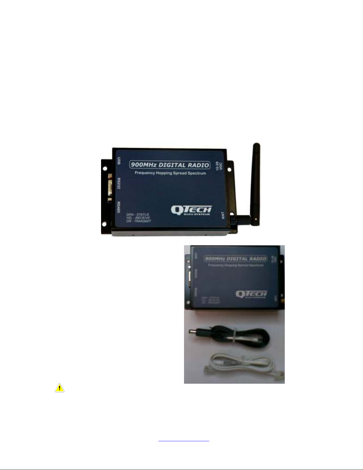
Each QDR (P/N PD9119-485) is supplied
with the following:
Qty 1x QDR Radio
Qty 1x Internal Stub aerial, 2dBi gain
Qty 1x 1m Power Cable
Qty 1x 1m Serial Cable RS485
Alternatively P/N PD9119-232 is the
RS232 version which is supplied with a
1m RS232 serial cable.
A range of quality external aerials are
also available:
PD9225 - 4 element Yagi, 9dBi gain with
5m coax and SMA connector
PD9218 - Whip aerial, 5dBi gain with 5m
coax, bracket and SMA connector
Note – The RS485 cable differs depending on whether connecting to a XL4
RTU (RJ12 to RJ12) or another device (RJ12 to RJ10), the respective P/N are
CB-QDR-RS485-XL4 & CB-QDR-RS485.
www.qtech.co.nz Tel: 03 3663713
Page 5
QDR – QTech Digital Radio – Owners Manual – v1.3 – August 2012 5
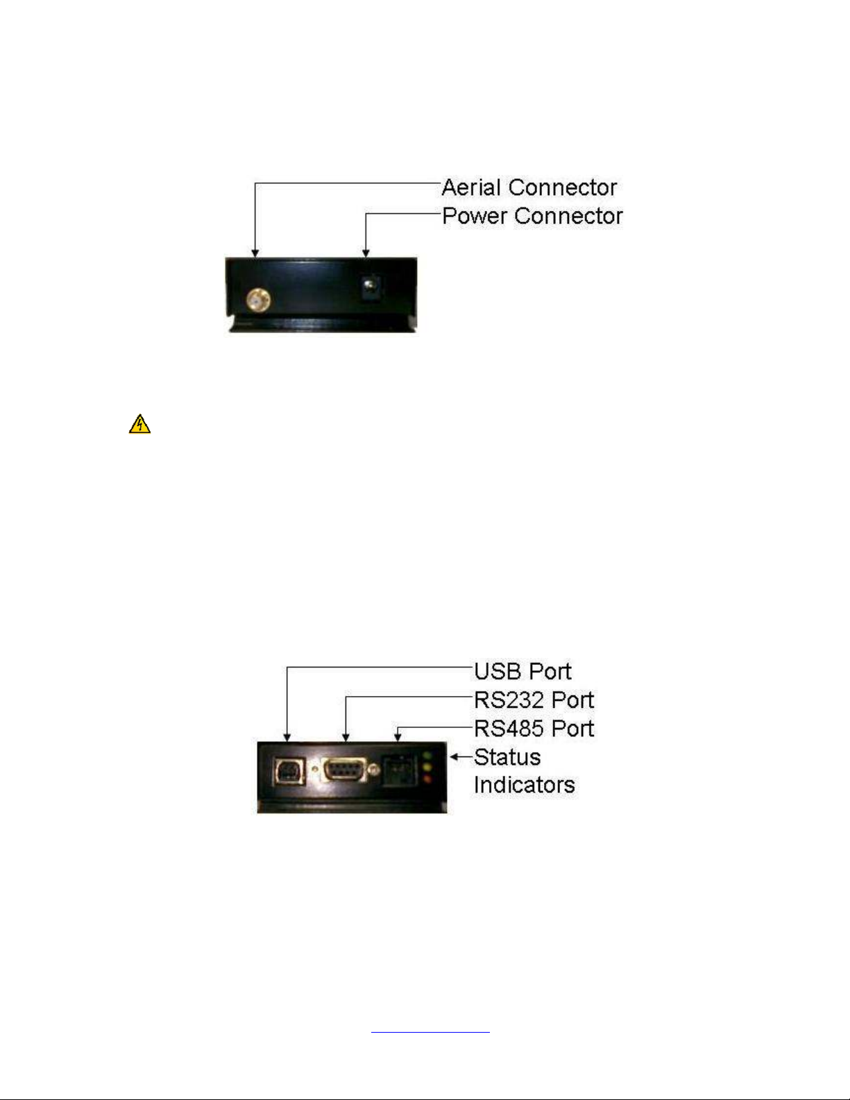
3.0 Connections
The connections of the QDR are identified below:
3.1 Power Connector – 2.1mm DC Socket
Centre pin +V.
Spare power cables are available, P/N CB-QDR-PWR.
Warning – Do NOT use Switch Mode Power Supplies (SMPS) with this
product. The DC power supply used for this product MUST have a grounded
negative or be a “linear” transformer based plug pack. The reason is that the
aerial, programming port and external connections can provide exposed earth
points and the SMPS can impose an AC voltage on the DC ground, which can
lead to damage. Suitable cost effective plug packs are available from QTech
P/N PD5412.
3.2 Aerial Connector – SMA Socket
This is used to connect a suitable aerial with an SMA plug. Please refer to the notes
in section 8 of this manual.
3.3 USB Port – Type B Socket
This is used for configuration via PC or upgrading the radio firmware.
3.4 RS232 Serial Port – DB9 Female Connector
This is used to connect to RS232 devices. Refer to applications.
Spare RS232 cables are available, P/N CB-QDR-RS232.
www.qtech.co.nz Tel: 03 3663713
Page 6

QDR – QTech Digital Radio – Owners Manual – v1.3 – August 2012 6
3.5 RS485 Serial Port – RJ12 Socket
This is used to connect to RS485 devices in either half or full duplex modes.
Refer to applications.
Spare RS485 cables are available, P/N CB-QDR-RS485.
Note – The RS485 cable differs depending on whether connecting to a XL4
RTU (RJ12 to RJ12) or another device (RJ12 to RJ10), the respective P/N are
CB-QDR-RS485-XL4 & CB-QDR-RS485.
4.0 Status Indicators
There are three status indicators on the QDR.
Colour Meaning Description
Green Status Indicates radio status
Yellow RxD Received valid (RF) data packet
Orange TxD Transmitted a packet
Notes
RxD LED blinks upon receiving a valid packet. A packet is valid if the Customer-ID
and Site-ID in the received packet are equal to the receiving radios Customer-ID and
Site-ID. The packets must also have a valid checksum.
Status LED issues 6 fast flashes to indicate that the QDR has been reset/repowered.
The Status LED flashes slowly to indicate the QDR processor is running correctly.
www.qtech.co.nz Tel: 03 3663713
Page 7

QDR – QTech Digital Radio – Owners Manual – v1.3 – August 2012 7
RS485
-
IPB
RS232
5.0 Applications
5.1 RS232 Mode
This is used for serial data communications.
A typical use of this mode would be:
DATRAN
Master RTU
The serial cable is connected from the RS232 port of the QDR to an RS232 port of
the RTU.
Pinout of RS232 Port and interface cable connections.
D9 Pin Signal Input/Output Description RJ45
1 DCD Output Data Carrier Detect
2 RxD Output Receive Data 2
3 TxD Input Transmit Data 6
4 DTR Input Data Terminal
5 GND - Ground 5
6 - - Not Connected
7 RTS Input Request To Send
8 CTS Output Clear To Send
9 RI Input Ring Indication
Slave RTU
Pin
Ready
5.2 RS485 – Half Duplex Mode
A typical use of this mode would be:
DATRAN RTU Remote I/O
Q23 or Q26
The serial cable is connected from the RS485 port of the QDR to the RS485/IPB port
of the RTU at a comms speed of 9600bps.
www.qtech.co.nz Tel: 03 3663713
Page 8

QDR – QTech Digital Radio – Owners Manual – v1.3 – August 2012 8
Jumper Settings for Half Duplex RS485 (2-Wire)
Refer to Section 6 for further details on the jumpers
Jumper Position
JP3 In
JP4 Out
JP5 In
JP6 In
Pinout of RS485 Port when in Half Duplex Mode
QDR XL4 eXcel
Signal Input/Output Description
Pin Pin Pin
1 1 1 (NC) GND - Ground
2 2 3 B Input/Output Inverting Input/Output
3 3 2 A Input/Output Non inverting Input/Output
4 4 4 (NC) - - -
5 5 - - -
6 6 GND - Ground
Typical Half Duplex Connection
120 Ohm
120 Ohm
Note: Line termination resistors are inside the QDR
www.qtech.co.nz Tel: 03 3663713
Page 9

QDR – QTech Digital Radio – Owners Manual – v1.3 – August 2012 9
5.3 RS485 - Full Duplex Mode
This mode is used for serial data communications where all four signal lines are
required.
Jumper Settings for Full Duplex RS485 (4-Wire)
Refer to Section 6 for further details on the jumpers
Jumper Position
JP3 In
JP4 In
JP5 Out
JP6 Out
Pinout of RS485 Port when in Full Duplex Mode
Pin Signal Input/Output Description
1 GND - Ground
2 B Input Inverting Receiver Input
3 A Input Non inverting Receiver Input
4 Z Output Inverting Driver Output
5 Y Output Non inverting Driver Output
6 GND - Ground
Typical Full Duplex Connection
120 Ohm
120 Ohm
120 Ohm
120 Ohm
Note: Line termination resistors are inside the QDR
www.qtech.co.nz Tel: 03 3663713
Page 10

QDR – QTech Digital Radio – Owners Manual – v1.3 – August 2012 10
6.0 Jumper Settings
A list of all jumpers and their positions on the QDR has been provided for reference.
Jumper Description
JP1 ISP Programming Enable
JP2 ISP Programming Enable
JP3 RS485 120 Ohm Line termination on A-B
JP4 RS485 120 Ohm Line termination on Y-Z
JP5 RS485 A-Y Link
JP6 RS485 B-Z Link
JP7 RF Power Amplifier Bias Disconnect
www.qtech.co.nz Tel: 03 3663713
Page 11

QDR – QTech Digital Radio – Owners Manual – v1.3 – August 2012 11
7.0 Configuration Parameters
The QDR is configured by QTech via the USB Port using a desktop application.
The available parameters are defined below:
Parameter Options Notes
Radio Type
Hopping Sequence 1-6
Power Level 1-8 1 = 1 mW
Customer Number 1-255
Site Number 1-255
Radio Address 1-255
RSSI Mute Threshold -128 – 0 dBm
Background RSSI -128 – 0 dBm Read only
Packet RSSI -128 – 0 dBm Read only
Firmware Version Read only
MAC Address Read only
2-wire RS485
4-wire RS485
RS232
Standalone Repeater
Repeater with 2-wire RS485
Repeater with 4-wire RS485
Repeater with RS232
6 = 125 mW for Yagi
7 = 250 mW
8 = 500 mW for Collinear
www.qtech.co.nz Tel: 03 3663713
Page 12

QDR – QTech Digital Radio – Owners Manual – v1.3 – August 2012 12
8.0 Important Notes and Warnings
Aerial Connection
The QDR should never be operated without an aerial connected. If the radio transmits
without an aerial the RF power has nowhere to go but back into the radio, which can
damage it.
Transmitted RF Power Levels
The QDR must never be operated in violation of RSM license conditions. Ensure that the
Transmit Power Level and aerial system design do not exceed the limitation.
Please be considerate of other users of the ISM Band.
AS/NZS 4268:2008 specifies a maximum EIRP of 1 watt.
Warning – Do NOT use Switch Mode Power Supplies (SMPS) with this
product. The DC power supply used for this product MUST have a grounded
negative or be a “linear” transformer based plug pack. The reason is that the
aerial, programming port and external connections can provide exposed earth
points and the SMPS can impose an AC voltage on the DC ground, which can
lead to damage. Suitable cost effective plug packs are available from QTech
P/N PD5412.
Note – SMA Aerial Connectors
QDR. The aerial connector on the QDR
uses the standard/conventional polarity
SMA socket.
QTech supplies suitable aerials for the
QDR with a standard SMA plug, as
shown to the right.
XTend Radio. If you are using QDRs to
upgrade an existing system, such as
from Digi XTend radios, this must be
stated at time of ordering.
The Digi XTend type radio uses a non
standard, reverse polarity SMA
connector, often referred to as RP-SMA,
as shown to the right.
QDR Type Aerial Cable
XTend Type Aerial Cable
www.qtech.co.nz Tel: 03 3663713
Page 13

QDR – QTech Digital Radio – Owners Manual – v1.3 – August 2012 13
A QDR variant is available which has a reverse polarity RP-SMA aerial connector
which will allow you to use the existing aerials. Please order P/N PD9119-U/G.
Note – The RS485 cable differs depending on whether connecting to a XL4
RTU (RJ12 to RJ12) or another device (RJ12 to RJ10), the respective P/N are
CB-QDR-RS485-XL4 & CB-QDR-RS485.
Troubleshooting
Symptom Cause Solution
Green Status LED not
blinking when power
applied
No Communication RS485 jumpers not
RS485 line termination Check settings and change
Incorrect serial data rate Check settings, ensure it is
Insufficient Rx signal
Incorrect configuration for
* Be sure that the transmitted power from the antenna (EIRP) does not exceed the
licensed level.
Blown fuse Replace fuse. Use 1 Amp
quick blow type.
Insufficient power supply
voltage
matching setup mode
power
intended use
Check supply and provide
suitable power supply
Check settings and change
to suit
to suit
9600 Baud, No Parity
Use a directional antenna*
Use Workbench to measure
the RSSI. A value below -
95dbm is unlikely to be
reliable.
Options are point to point,
point to multipoint, repeater
www.qtech.co.nz Tel: 03 3663713
Page 14

QDR – QTech Digital Radio – Owners Manual – v1.3 – August 2012 14
9.0 Specifications
Performance
Indoor/Urban range (2.1dBi dipole antenna): Up to 500m
Outdoor line-of-site range (2.1dBi dipole antenna): Up to 5km
Outdoor line-of-site range (9dBi high gain yagi antenna): Up to 10km
Interface data rate: 9600bps
RF data rate: 9600bps
Receiver sensitivity: -110dBm
Power Requirements
Power supply voltage: 7 – 28 volts (30 volts absolute max)
Standby supply current: 85mA @ 12 volts
Transmit supply current: 150mA @ 12 volts
Specification
Frequency: 921.5 – 928.0MHz
RF Output: 1mW to 250mW
Technology: FHSS (Frequency Hopping Spread Spectrum)
Modulation: GFSK (Gaussian Frequency Shift Keying)
Hopping Channels: 6
Modes: point-to-point, point-to-multipoint, repeater
Maximum packet size: 256 bytes
Environmental
0º to 70º (non condensing)
Certification
AS/NZS 4268:2008
Network Configuration
Customer ID: 1 to 255
Site No.: 1 to 255
Radio Address: 1 to 255
Channel No: 1 to 6
RF Power Level: 1 to 8
Repeater Mode: ON/OFF
Serial Mode: None/RS232/RS485-2W/RS485-4W
Specifications may be subject to change.
www.qtech.co.nz Tel: 03 3663713
Page 15

QDR – QTech Digital Radio – Owners Manual – v1.3 – August 2012 15
User Notes
www.qtech.co.nz Tel: 03 3663713
 Loading...