


QT3
Q-TECH
COR PORATI ON
Description
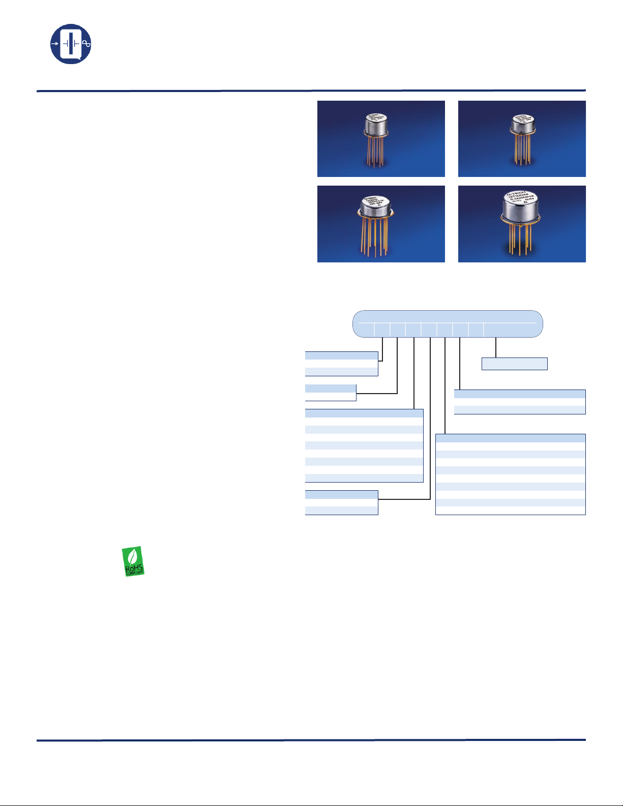
Q-Tech’s Transistor Outline package crystal oscillators
consist of a source clock square wave generator, logic
output buffers and/or logic divider stages, and a round AT
high-precision quartz crystal built in an all metal TO
package.
Features
• Made in the USA
• ECCN: EAR99
• DFARS 252-225-7014 Compliant:
Electronic Component Exemption
• USML Registration # M17677
• Wide frequency range from 0.045Hz to 125MHz
• Available as QPL MIL-PRF-55310/09 and/10 (TTL)
and /12 (CMOS)
• Choice of TO packages and pin outs
• Choice of supply voltages
• Choice of output logic options ( CMOS, ACMOS,
HCMOS, LVHCMOS, and TTL)
• AT-Cut crystal
• All metal hermetically sealed package
• Tight or custom symmetry available
• Low height available
• External tuning capacitor option
• Fundamental and third overtone designs
• Tristate function option D
• Three-point crystal mounts
• Custom design available tailors to meet customer’s
needs
• Q-Tech does not use pure lead or pure tin in its
products
• RoHS compliant
Applications
TRANSISTOR OUTLINE PACKAGES
TO-5 and TO-8 CRYSTAL CLOCK OSCILLATORS
1.8 to 15Vdc - 0.045Hz to 125MHz
Ordering Information
Sample part number
QT1ACD5M-20. 0 0 0 M H z
QT1AC D5M-60.000MHz
Solder Dip Option:
T = Standard
S = Solder Dip (*)
Package:
(See page 3)
Logic & Supply Voltage:
C = CMOS +5.0V to +15.0V
AC = ACMOS +5.0V
HC = HCMOS +5.0V
T = TTL +5.0V
L = LVHCMOS +3.3V
N = LVHCMOS +2.5V
R = LVHCMOS +1.8V
Z = Z output
Tristate Option:
Blank = No Tristate
D = Tristate
(*) Hot Solder Dip Sn60/Pb40 per MIL-PRF 55310 is optional for an additional cost
(**) Please specify supply voltage when ordering CMOS
For frequency stability vs. temperature options not listed herein, please request a
custom part number.
For Non-Standard requirements, contact Q-Tech Corporation at
(**)
1 = ± 100ppm at 0ºC to +70ºC
3(***) = ± 5ppm at 0ºC to +50ºC
4 = ± 50ppm at 0ºC to +70ºC
5 = ± 25ppm at -20ºC to +70ºC
6 = ± 50ppm at -55ºC to +105ºC
9 = ± 50ppm at -55ºC to +125ºC
10 = ± 100ppm at -55ºC to +125ºC
11 = ± 50ppm at -40ºC to +85ºC
12 = ± 100ppm at -40ºC to +85ºC
(*** ) Requires an external capacitor
Sales@Q-Tech.com
Output Frequency
Blank=No Screening
Frequency vs. Temperature Code:
Screening Option:
M=Per MIL-PRF-55310, Level B
• Designed to meet today’s requirements for all voltage
applications
• Wide military clock applications
• Industrial controls
• Microcontroller driver
Q-TECH Corporation - 10150 W. Jefferson Boulevard, Culver City 90232 - Tel: 310-836-7900 - Fax: 310-836-2157 - www.q-tec h.com
Transistor Outline Packages (Revision F, March 2011 ) (ECO# 10145)
Packaging Options
• Standard packaging in black foam
Other Options Available For An Additional Charge
• P. I. N. D. test (MIL-STD 883, Method 2020)
• Lead trimming
All Transistor Outline packages are available in surface mount form.
Specifications subject to change without prior notice.
1
Q-TECH
COR PORATI ON
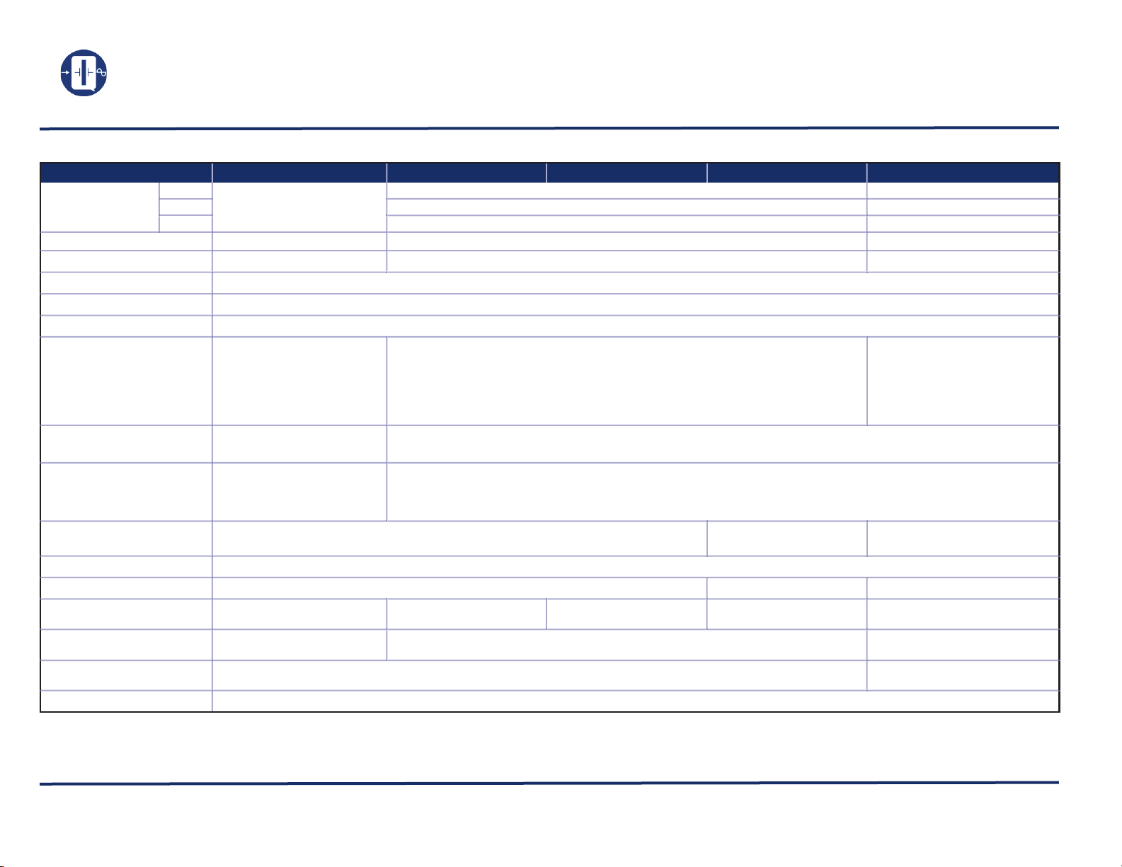
Electrical Characteristics
TRANSISTOR OUTLINE PACKAGES
TO-5 and TO-8 CRYSTAL CLOCK OSCILLATORS
1.8 to 15Vdc - 0.045Hz to 125MHz
Parameters C AC HC
QT1, 14
Output freq. range (Fo)
Supply voltage (Vdd)
Maximum Applied Voltage (Vdd max.) -0.5 to +18Vdc
Freq. stability (∆F/∆T)
Operating temp. (Topr)
Storage temp. (Tsto)
Operating supply current
(Idd) (No Load)
Symmetry
(50% of ouput waveform or 1.4Vdc for
TTL)
Rise and Fall times
(with typical load)
Output Load
Start-up time (Tstup) 10ms max.
Output voltage (Voh/Vol)
Output Current (Ioh/Iol)
Enable/Disable
Tristate function Pin 1
Jitter RMS 1σ (at 25ºC)
Aging (at 70ºC)
QT2
QT3
244Hz — 15MHz
5V ~ 15Vdc ± 10%
F and Vdd dependent
3 mA max. at 5V up to 5MHz
25 mA max. at 15V up to 15MHz
45/55% max. Fo < 4MHz
40/60% max. Fo ≥ 4MHz
30ns max.
(Measured from 10% to 90%)
± 1mA typ. at 5V
± 6.8mA typ. at 15V
Call for details
15pF // 10kΩ 10TTL Fo < 20MHz
0.9 x Vdd min.; 0.1 x Vdd max. 2.4V min.; 0.4V max. 0.9 x Vdd min.; 0.1 x Vdd max.
± 24mA
8ps typ. - < 40MHz
5ps typ. - ≥ 40MHz
± 5ppm max. first year / ± 2ppm typ. per year thereafter
732.4Hz — 85MHz
0.045Hz — 85MHz
732.4Hz — 85MHz
5.0Vdc ± 10% 3.3Vdc ± 10%
-0.5 to +7.0Vdc
See Option codes
See Option codes
-62ºC to + 125ºC
20 mA max. - 0.045Hz ~ < 16MHz
25 mA max. - 16MHz ~ < 40MHz
35 mA max. - 40MHz ~ < 60MHz
45 mA max. - 60MHz ~ 85MHz
(Measured from 10% to 90% CMOS or from 0.8V to 2.0V TTL)
±8 mA -1.6mA / TTL
VIH ≥ 2.2V Oscillation;
VIL ≤ 0.8V High Impedance
T
45/55% max. Fo < 12MHz
40/60% max. Fo ≥ 12MHz
15ns max. Fo < 15kHz
6ns max. Fo 15kHz ~ 39.999MHz
3ns max. Fo 40MHz ~ 125 MHz
6TTL Fo ≥ 20MHz
+40μA / TTL
L (*)
732.4Hz — 125MHz
0.045Hz — 85MHz
732.4Hz — 85MHz
-0.5 to +5.0Vdc
3 mA max. - 0.045Hz ~ < 500kHz
6 mA max. - 500kHz ~ < 16MHz
10 mA max. - 16MHz ~ < 32MHz
20 mA max. - 32MHz ~ < 60MHz
30 mA max. - 60MHz ~ < 100MHz
40 mA max. - 100MHz ~ 125MHz
15pF // 10kΩ
± 4mA .
VIH ≥ 0.7 x Vdd Oscillation;
VIL ≤ 0.3 x Vdd High Impedance
15ps typ. - < 40MHz
8ps typ. - ≥ 40MHz
(*) Available in 2.5Vdc (N) or 1.8Vdc (R)
Z Output logic can drive up to 200 pF load with typical 6ns rise & fall times (tr, tf)
ECL, PECL, LVPECL are available. Please contact Q-Tech for details.
Q-TECH Corporation - 10150 W. Jefferson Boulevard, Culver City 90232 - Tel: 310-836-7900 - Fax: 310-836-2157 - www.q-t ech.co m
Transistor Outline Packages (Revision F, March 2011 ) (ECO# 10145)
2
 Loading...