

Page 1

Q70 – Base Station Radio Modem
Quick Start Guide
Page 2
Q70 – Quick Start Guide – v1.1 – December 2011
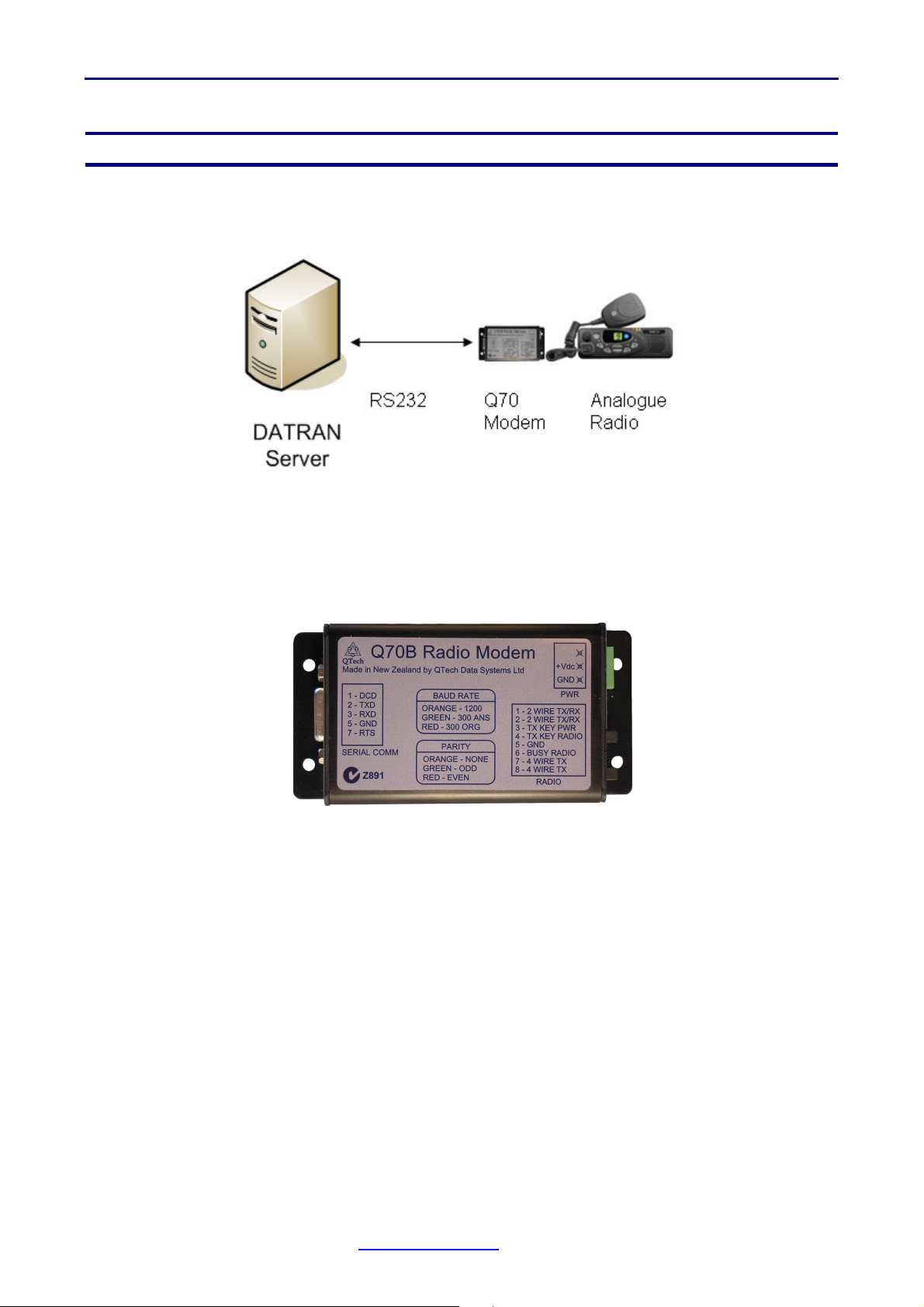
INTRODUCTION
The Q70 Data Modem has been designed to reliably transmit and receive RS232 data and
is the ideal modem for DATRAN base station.
The modem is a direct replacement of the previous DATRAN base station modem, part
number PD9300 (300bps) and PD9301 (1200bps).
The Modem is supplied complete with a serial interface lead and a dedicated 12V DC plug
pack to simplify the introduction.
The modem can be configured as 300bps or 1200bps, 2 wire or 4 wire and has multicolour
status LED indicators to confirm the configuration.
LED Indication is also provided for the status of Tx, Rx, DCD, RTS and Tx Key.
The modem can be supplied to your exact system requirements if specified at time of
ordering.
Each modem is supplied with:
1x Q70 Modem
1x Cable From Q70 modem to Radio (RJ45 to Circular DIN)
1x 12V Mains Plug pack
If you require the serial cable from the modem to the PC, please order part number CBQ70 which is a ~1m D9F (female) to D9M (male). These are widely available as “straight
through” serial cables.
www.qtech.co.nz Tel: 03 3663713
Page 3

Q70 – Quick Start Guide – v1.1 – December 2011
MODEM CONFIGURATION
DIP Switch Settings
Inside the Q70 modem case is a bank of 8 DIP switches.
To access the DIP switches, remove the two Phillips head screws holding the endplates to
the case. Either end can be removed.
The function of the DIP switches is defined below:
Before applying power, set the DIP switches to the required position.
Setting the DIP switches is generally a one off task required before commissioning.
In normal operation the DIP switches do not need to be accessed.
Jumper Settings
Inside the Q70 modem case there are four PCB jumpers.
The function of these jumpers is defined below:
www.qtech.co.nz Tel: 03 3663713
Page 4

Q70 – Quick Start Guide – v1.1 – December 2011
Before applying power, set the PCB jumpers to the required position.
Setting the PCB jumpers is generally a one off task required before commissioning.
In normal operation the PCB jumpers do not need to be accessed.
QTech supply the Q70 modems preconfigured to your existing settings. Please advise if
this is required.
MODEM CONNECTIONS
Serial Connector - D9 Female
The connector is labelled “Serial Connector” and
connects the Modem to the base station PC.
Pin Number Function
1 Data carrier detect (DCD) from modem to terminal.
2 Receive data from modem to terminal.
3 Transmit data from terminal to modem.
4 Not Used.
5 Signal ground.
6 Not Used.
7 Ready to Send (RTS) from terminal to modem.
8 Not Used
9 Not Used.
If you require the serial cable from the modem to the PC, please order part number CBQ70 which is a ~1m D9F (female) to D9M (male). These are widely available as “straight
through” serial cables.
www.qtech.co.nz Tel: 03 3663713
Page 5

Q70 – Quick Start Guide – v1.1 – December 2011
Radio Connector - RJ 45
The connector is labelled “Radio” and connects the
Modem to the audio interface on the radio.
Pin 1 is on the left hand side, nearest the fixing screw.
The cable from this connector to the radio is provided with each Q70 modem
Pin Number Function
1 2 Wire Transmit and receive audio data.
2 2 Wire Transmit and receive audio data.
3 Transmitter Key Power.
4 Transmitter key from Radio.
5 Ground.
6 Busy from Radio.
7 4 Wire Transmit
8 4 Wire Transmit.
3 Pin Power Supply Connector
Pin Number Function
1 Not Connected
2 + Supply 8-30V DC
3 Ground
The Q70 modem is supplied with a 12V DC plug pack with a pre terminated power
connector.
www.qtech.co.nz Tel: 03 3663713
 Loading...