

Page 1

Q23 – DATRAN II eXcel I/O Expansion
Quick Start Guide
Page 2
DATRAN II eXcel - Q23 Quick Start Guide – v2.0 – September 2010
Module Address
As an IO expansion module that communicates with the master RTU (eXcel or QRTU) on
the RS485 bus, the module must have an address that is unique to that bus. The
expansion module is factory preset to address 3. Therefore if multiple expansion modules
are to be used on the same RS485 bus then their addresses must be configured. This is
achieved by setting a code on the block of 8 DIP switches located internally to the IO
expansion module casing.
The code for address is a binary code with switch 1 being the least significant bit. This
means that each switch has a numeric value associated with it, and the resultant address
is calculated when you add all the switch values that are in the “ON” state.
The module address can be any number between 1 and 239. The module address 0 is a
reserved address while module address 255 is used to re-load the factory default
configuration settings.
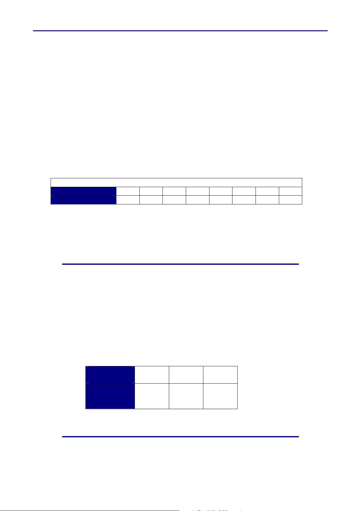
The value of each switch is as follows:
Module Address Switch Values
Switch Number 1 2 3 4 5 6 7 8
Value 1 2 4 8 16 32 64 128
For example, if a module needs an address of 22, the correct setting would be to have
switches 2,3 and 5 on and the rest off. (2+4+16 = 22).
The back of the Q23 Users Guide has a full table of all valid addresses and their
corresponding DIP switch settings.
Status LED’s
ON : This LED is always on when the module is powered.
OK : This LED flashes on a 1 second cycle to show the CPU has not locked
up. If it is on solidly or stays off, then the eXcel needs attention.
IP : This LED indicates that the module is currently sending comms out its
IPB port to communicate with the RTU.
ER : This is the Error Indication LED. The LED will flash a certain number of
times to indicate any error messages the module has been configured
to display from Q90.
Number of
Flashes
Message
4 5 6
IPB
Comms
Fail
Digital
Outputs
Fail
Analog
Inputs
Fail
Page 3

DATRAN II eXcel - Q23 Quick Start Guide – v2.0 – September 2010
Power Supply Connections
The module is able to operate from 12V - 30VDC.
The module power connector has three connections labeled “G”, “+” and “C”.
G Power Supply Negative
+ Power Supply Positive (12V – 30VDC)
C Option for remote power control from a
master RTU.
The “C” terminal is a control INPUT. Do not connect it to the supply
Factory Presets
When you receive your Q23 IO Expansion module it will be configured with the following
settings:
RS485 Address 3 (as configured by the internal dipswitch setting)
RS485 Baud Rate 9600
Digital Inputs
The module digital inputs are designed to interface easily with physical
switching devices. They have an internal pull-up resistor that will pull the
input terminal to the power supply ‘+’ when the input is open circuit (the
“OFF” state).
To turn a digital input ON, connect it (via a set of contacts if necessary) to
the common “G” terminal on the Digital Input terminal block. All “G”
terminals on the module are tied internally to the “G” terminal on the power
supply connector.
The LED associated with each digital input will light up when the input is
Active/On/Closed.
The pull up / pull down convention is different from some PLCs. If required, the
active state of I/O can be inverted in the eXcel control program or PLC
Page 4

DATRAN II eXcel - Q23 Quick Start Guide – v2.0 – September 2010
Digital Outputs
As with the Digital Inputs, the module Digital Outputs are designed to be easily interfaced
with relays and contactors.
The module has 8 Digital Outputs in total. The first four are located on the front panel
adjacent to the Digital Inputs and have LED indicators to show if the output is active or not.
The second four Digital Outputs are located on the underside of the module next to the
power connector, labeled “Aux Out”.
+ Supply
The Digital Outputs work as “Current Sinks”. This means that when
they are turned on, they will be connected to power supply ground,
allowing current to flow into the output terminal to ground. When in the
RTU
“OFF” state, they have a high impedance to ground and will float up to
+ Supply.
Dig Out 1
To use a digital output with a relay, wire as shown in the diagram
opposite:
Analog Inputs
The module has 6 analog channels. All analog channels are independently capable of
operation as either 0-20 mA, 4-20 mA, 0-5 V or 0-10 V. In addition to this, channels 5 and
6 are independently able to be configured as either inputs or outputs. The module comes
factory shipped with all analog channels configured as 4-20 mA inputs. For details on how
to reconfigure them, refer to the DATRAN II eXcel Users Guide.
For all analog inputs, the current return path is via the ground of the module power supply.
It is important to understand the implications of this when wiring certain analog devices to
the module, as detailed below.
The LED’s adjacent to each Analog Input show the status of the signal the eXcel is
receiving. If the LED is off, it means the input signal is zero, or under-range. When the
LED is on, it indicates the signal is within the measuring range that the input has been
configured for. If the LED is flashing, it shows the signal is over-range.
Loop Powered Devices
“Loop-Powered”, or “2-Wire” devices derive their power supply from the current flowing in
the loop itself. It is important to make sure that any device is rated to operate at the voltage
that will be available to it taking into account that the eXcel Analog Input will drop 5 v
across it at 20 mA loop current.
For example: If the system is being powered from 13.7 VDC, the
analog transducer will only have a maximum of 8.7 volts available to it
for its power supply.
To wire a “2-Wire” device, refer to the diagram opposite:
Separately Supplied Devices
“Separately Supplied”, or “4-Wire” devices are analog transmitters that
have a separate power supply from the analog signal loop. If suitable,
these devices can be powered from the eXcel power supply. If the
eXcel power supply is not suitable, the analog sensor can be powered
from a separate power supply as long as the grounds of both the eXcel
and the other power supply are connected together.
Wiring of a 4-Wire device is as shown:
RTU
+
Anl In 1
RTU
Tx
Anl In 1
G
Tx
 Loading...