

Page 1

EP1 – Q03 Programming Dongle
Quick-Start Guide
Page 2
EP1 – Q03 Programming Dongle - Quick Start Guide – v1.2 – 10 September2010 2
Introduction
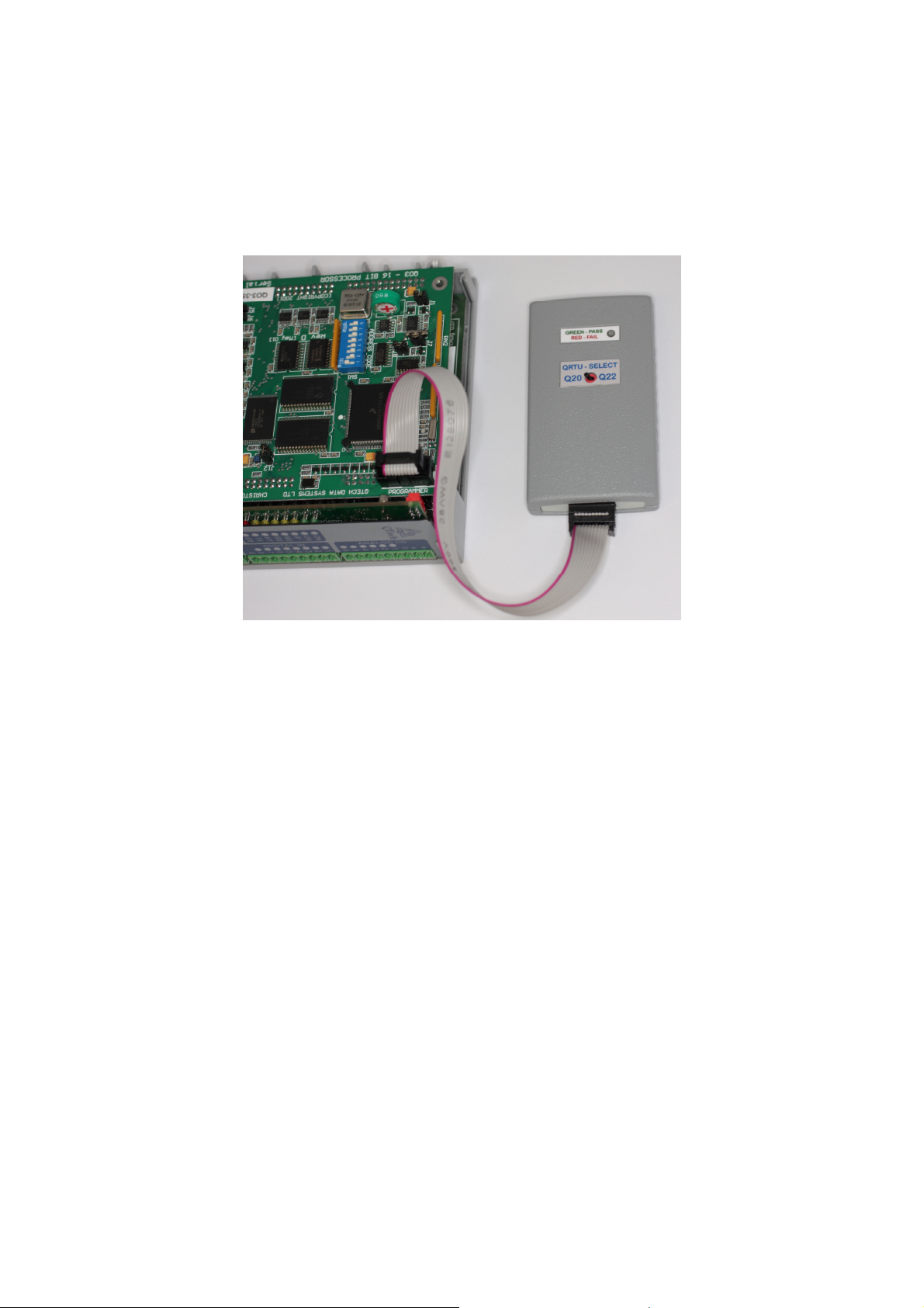
The EP1 Programming Dongle is used to upgrade the firmware of Q03 DATRAN
RTUs. The EP1 can be used to upgrade Revisions B, C, D & E Q03 Processors for
both QRTU and DATRAN II eXcel RTUs.
This photograph shows the EP1 connected to a Revision D Q03 Processor.
The following is a detailed step by step procedure for updating the firmware in a Q03
Processor. Each step should be completed in the order shown.
Requirements
We have endeavoured to make the practical use of the EP1 as simple as possible.
However, there are several important prerequisites to the successful use of the EP1.
Please remember that the programming of micro controllers is a specialised task and
only technical staff that are capable, confident and have experience of DATRAN
should complete it.
• The EP1 Programming Dongle installed with the latest Q03 firmware and the
loaded with the required quantity of upgrade licenses.
• A notebook or other portable computer running Q90 v3.27.
• Q90 Diagnostics cable (QTech part PD6502) RTU to PC serial cable.
• An existing understanding of the operation of the Q90 Configuration and
Diagnostic Program and familiarity of DATRAN RTUs.
• Flat blade screwdriver, small pair of pointed nose pliers.
Page 3

EP1 – Q03 Programming Dongle - Quick Start Guide – v1.2 – 10 September2010 3
Upgrade Instructions
1. Install the Q90 serial cable between the RTU and PC. Using the Q90 program
press the Save Configuration button from the File Menu. Save the current Q03
configuration to a folder or the Desktop. It is recommended that you include the
site name and/or date in this file name to assist with record keeping.
Please remember that completing an upgrade will loose the DLP, real time clock
(RTC) setting and any RTU Data Logging settings. These need to be reloaded
after completion.
2. Remove the power to the RTU containing the Q03 to be upgraded. Remove any
necessary cables, covers, etc to gain access to the Q03 Processor.
3. Note down the current Q03 ADDRESS CODE settings from the DIP switches.
4. Locate Jumper J8 on the Q03 Processor and install the shorting link onto the pins
of J8. Refer to Figure 1 for typical locations.
5. Install the EP1 10-way ribbon cable plug into the mating 10 pin socket labelled
PROGRAMMER on the Q03 Processor. Refer to Figure 1 for locations.
6. Set the QRTU Select switch on the EP1 programmer to the required RTU
motherboard type, i.e. Q20 for QRTU or Q22 for eXcel RTU.
7. Re-power the Q03 Processor by applying power to the RTU motherboard.
8. The EP1 LED indicators will flash alternatively Red and Green for approximately
40 seconds. Do not remove power during this time.
After the alternate flashing, the green LED will flash to indicate that the firmware
in the RTU has been upgraded and a license has been used.
If the green LED is on continuously it means that the Q03 firmware in the RTU
has not changed as it is the same version as that in the Dongle. A license has not
been used.
In both cases, the Q03 Processor OK LED should now flash in the usual manner.
9. If the EP1 Red LED indicator is flashing or continuously on, then the programming
of the Q03 Processor has failed. The power to the motherboard should be
removed for a few seconds and then steps 7 and 8 above should be repeated.
10. Once the Q03 Processor has been successfully reprogrammed the power should
be removed from the motherboard and then remove the EP1 ribbon cable.
11. Remove Jumper J8. Locate and remove Jumper J1. Wait 60 seconds and then
replace Jumper J1. This action clears the battery backed configuration data from
the Q03 Processor memory. Refer to figure 1 for location.
12. Set the ADDRESS CODE DIP switches to all ON. This is address 255 which
performs the “restore factory default”. Repower the Q03 Processor. After a short
while the green OK LED on the Q03 Processor should flash in the usual manner.
13. Set the ADDRESS CODE DIP switches to the setting noted in Step 3 above.
Page 4

EP1 – Q03 Programming Dongle - Quick Start Guide – v1.2 – 10 September2010 4
14. Complete this step only if the version of firmware you are upgraded from is prior
to v5.0, otherwise go to step 15. Close Q90. Run the “Q03 Options fix” program,
supplied on the CD with your EP1, and follow these simple steps.
Select the Com port in
use and press Fix
This step ensures that firmware options that were not available when the Q03 was
originally manufactured are correctly cleared. This does not affect any firmware
options (AB-DF1, Modbus etc) that the RTU currently uses.
15. Using Q90 program press Open Configuration from the File menu to restore the
RTU configuration file saved in Step 1 above.
16. Step through the various Q90 Configuration options to ensure that the RTU is
configured correctly making any changes or adjustments as necessary before
reinstallation.
If successful, this
dialogue appears.
If unsuccessful, this dialogue
appears. Please retry.
Page 5

EP1 – Q03 Programming Dongle - Quick Start Guide – v1.2 – 10 September2010 5
Figure 1 – Layout of the Q03 Revision D Processor
The location of the jumper positions is different for older Revision B and C Q03s.
Important Notes and Warnings
Anti Static
The Q03 Processor incorporates static discharge sensitive devices. Normal Anti
Static Discharge precautions should be employed when handling the Q03 Processor.
Q03 firmware earlier than IN180
Firmware earlier than IN180 does not support the saving or loading
of RTU configuration files by Q90. For these old versions of firmware, a manual
written note must be taken of all configurations before upgrading.
DATRAN II eXcel RTU display boards (Q24).
DATRAN Product Bulletin 2010-001outlines that care needs to be taken when
upgrading firmware prior to v5.01. A copy of the Bulletin is on the supplied CD. The
Q24 display board may also need upgrading. To simplify this, each EP1 is delivered with a
new Q24 display board in the packaging. This does not affect QRTU upgrades.
Reinstalling the RTU
When the upgrade is complete, the RTU will not have a DLP, the time (RTC) will not
be correct and it will not have any Data Logging configuration. Please remember
to transmit these from the base station, or use Q90, as soon as the RTU is reinstalled.
Page 6

EP1 – Q03 Programming Dongle - Quick Start Guide – v1.2 – 10 September2010 6
Troubleshooting
The Red/Green LED on the front of the EP1 Programming Dongle indicates the
status of each RTU firmware upgrade as follows:
Green LED
• On continuously - Indicates that the firmware in the Q03 and the EP1 are
verified to be identical. No license was used.
• Flashing – Indicates that the firmware in the Q03 has been upgraded to that
in the EP1 and verified. One license has been used.
Red LED
• On continuously – Indicates that the firmware was installed into the Q03 but
did not verify. No license was used. Check that the jumper J8 is properly
installed. The RTU should be reprogrammed by repeating steps 4 onwards as
described above. If the fault persists then a fault may have occurred in the
RTU.
• Flashing Code 2 – There are no licenses remaining on the EP1 Programming
Dongle.
• Flashing Code 3 – The RTU firmware installed in the EP1 is either corrupted
or missing.
• Flashing Code 4 – The EP1 has developed a hardware fault and should be
returned to QTech for servicing.
Flash codes are a stream of flashes separated by a gap of approximately one
second.
Page 7

EP1 – Q03 Programming Dongle - Quick Start Guide – v1.2 – 10 September2010 7
User’s Notes
 Loading...