

Page 1
QSDT8DP DVR User’s Manual
QSDT8DP
DVR User’s Manual
For H.264-240 FPS /8-channel digital video recorder
All rights reserved
Rev 120209
i
Page 2

QSDT8DP User’s Manual
CAUTION
Please read this user manual carefully to ensure that you can use the
device correctly and safely
The contents of this manual are subject to change without notice
This device should be operated only with the power source supplied
with the unit. The power supply voltage must be verified before using. If
not going to be used for a long time, unplug the unit from the outlet
Do not install this device near any heat sources such as radiators, heat
registers, stoves or other devices that produce heat
Do not install this device near water. Clean only with a dry cloth
Do not block any ventilation openings, and make sure the area around
the machine is well ventilated
This machine is designed for indoor use. Do not expose the machine to
water or a moist environment. If any solid or liquid gets into the machine’s
case, please cut off the power supply immediately, and have the unit
checked be a qualified technician before restart
Refer all servicing to qualified service personnel. There are no parts in
the unit you can service yourself.
ii
Page 3

QSDT8DP DVR User’s Manual
CONTENTS
CHAPTER 1 Introduction ..................................................................................... 1
1.1 DVR Introduction ............................................................................................ 1
1.2 Main Features ................................................................................................ 1
1.3 DVR Introduction ............................................................................................ 1
1.4 Main Features ................................................................................................ 2
CHAPTER 2 Hardware Installation ...................................................................... 4
2.1 Installing Hard Drive ....................................................................................... 4
2.2 Front Panel Layout ......................................................................................... 5
2.3 Rear Panel Layout ......................................................................................... 6
2.3.1 Installing Sensors & Alarms (optional) ........................................................................... 6
2.4 Remote Control .............................................................................................. 8
2.5 Controlling with a Mouse ................................................................................ 9
2.5.1 Connecting Mouse ........................................................................................................ 9
2.5.2 Using Mouse ................................................................................................................. 9
CHAPTER 3 Basic Function Instructi o ns ............................................................ 10
3.1 Power On/Off ............................................................................................... 10
3.2 Login & User Management ........................................................................... 11
3.3 Recording ..................................................................................................... 14
3.3.1 Rec ord Setup .............................................................................................................. 14
3.3.2 Manual Recording ....................................................................................................... 15
3.3.3 Scheduled Recording .................................................................................................. 15
3.3.4 Motion Detection Recording ........................................................................................ 16
3.3.5 Alarm Recording ......................................................................................................... 17
3.4 Playback ....................................................................................................... 18
3.5 Backup & View ............................................................................................. 20
3.6 PTZ Control .................................................................................................. 26
CHAPTER 4 Menu Setup Guide.......................................................................... 28
4.1 Menu Navigation .......................................................................................... 28
4.2 Main Menu Setup ......................................................................................... 29
4.2.1 Basic Configuration ..................................................................................................... 30
4.2.2 Live Configuration ....................................................................................................... 31
4.2.3 Record Configuration .................................................................................................. 32
4.2.4 Schedule Configuration ............................................................................................... 33
4.2.5 Alarm Configuration .................................................................................................... 33
4.2.6 Motion Configuration ................................................................................................... 35
4.2.7 Network Configuration................................................................................................. 36
4.2.8 P.T.Z Configuration ...................................................................................................... 38
4.2.9 Us er Configurat ion ...................................................................................................... 39
4.2.10 Tools Configuration ................................................................................................... 39
CHAPTER 5 Managing the DVR ....................................................................... 40
5.1 Formatting the Hard Disk ............................................................................. 40
5.2 Updating Firmware ....................................................................................... 40
5.3 Load Default Setup ...................................................................................... 41
5.4 Check System Information ........................................................................... 41
5.5 Check System Log ....................................................................................... 43
5.6 Check On-line Network Users ...................................................................... 44
5.7 Lock & Delete Files ...................................................................................... 45
iii
Page 4

QSDT8DP User’s Manual
CHAPTER 6 Remote Surveillance ................................................................... 46
6.1 Accessing the DVR ...................................................................................... 46
6.1.1 On L AN....................................................................................................................... 46
6.1.2 On WAN ..................................................................................................................... 47
6.2 Remote Viewing ........................................................................................... 48
6.3 Remote Playback &Backup .......................................................................... 52
6.3.1 Remote Playback ........................................................................................................ 52
6.3.2 Remote Backup .......................................................................................................... 54
6.4 Remote Menu Configuration ........................................................................ 55
6.5 Remote DVR Management .......................................................................... 56
6.5.1 Check System Log Remotely ...................................................................................... 56
6.5.2 Lock & Delete Fil es R emotely ..................................................................................... 57
CHAPTER 7 Mobile Surveillance ........................................................................ 58
7.1 Accessing From Phones with WinCE ........................................................... 58
7.2 Accessing From Phones with Symbian ........................................................ 60
7.3 Accessing From iPhones .............................................................................. 62
Appendix A FAQs ............................................................................................. 67
Appendix B Calculating Recording Capacity ................................................. 71
Appendix C Compatible Devices .................................................................... 72
Appendix D DVR Specifications ...................................................................... 73
Q-SEE Product Warranty ………………………………………………………………75
Customer Information Card .................................................................................... 75
iv
Page 5

QSDT8DP DVR User’s Manual
CHAPTER 1 Introduction
1.1 DVR Introduction
This DVR uses high performance video processing chips and an embedded
Linux system. It utilizes many adv ance d techn olo gie s, suc h as st an dar d
H.264 with low bit rate, Dual Stream, SATA interface, VGA output, supports
access by m ouse, IE browser supported with full remote control, mobile
viewing by cell phones, etc. it has very powerful functions and high stability. It
is widely used in banking, telecommunication, transportation, factories,
warehouses, irrigation, etc.
1.2 Main Features
COMPRESSION FORMAT
• Standard H . 264 compression with low bit rate. Backup file can be play ed
by normal player, without any software or codec instal led.
LIVE SURVEILLANCE
• Supports VGA output
• Supports channel security by hiding live display
• Displays the local record state and basic information
• Supports full control with USB mouse
• Supports system locking and u nloc ki ng
RECORDING MEDIA
• Supports 2 SATA HDDs to record for long time periods
1.3 DVR Introduction
This DVR uses high performance video processing chips and an embedded
Linux system. It utilizes many adv ance d techn olo gie s, suc h as st an dar d
H.264 with low bit rate, Dual Stream, SATA interface, VGA output, supports
access by m ouse, IE browser supported with full remote control, mobile
viewing by cell phones, etc. it has very powerful functions and high stability. It
is widely used in banking, telecommunication, transportation, factories,
warehouses, irrigation, etc.
1
Page 6

QSDT8DP DVR User’s Manual
1.4 Main Features
COMPRESSION FORMAT
• Standard H . 264 compression with low bit rate. Backup file can be play ed
by normal player, without any software or codec inst al led.
LIVE SURVEILLANCE
• Supports VGA output
• Supports channel security by hiding live display
• Displays the local record state and basic information
• Supports full control with USB mouse
• Supports system locking and u nloc ki ng
RECORDING MEDIA
• Supports 2 SATA HDDs to record for long time periods
BACKUP
• Supports USB flash drive for backup
• Supports saving recorded files to a remote computer through internet
RECORD & PLAYBACK
• Record modes: Manual, Schedule, Motion detection and Sensor alarm
recording
• Supports recycling after HDD is full
• Resolution, frame rate and picture quality adjustable for each channel
separately
• 64MB for every video file packaging
• 4 audio channels available
• Two record sear ch mod es: tim e search and event search
• Supports single and 4 screen playback
• Supports deleting and locking t he record ed file s individually
• Supports remote playback in Internet Explorer through LAN or internet
ALARM
• 16 channel alarm input and 4 channel alarm output available
• Supports schedule for motion detection and sensor alarm
• Supports pre-recording and post recording
• Supports linked channel recording onc e a mot ion or sensor alarm is
triggered on certain channels
• Supports linked PTZ presets and auto cruise on the corresponding
channel
PTZ CONTROL
• Supports various PTZ protocols
PelcoP, PelcoD, LILIN, MINKING, NEON, STAR, VIDO, DSCP, VISCA,
2
Page 7

QSDT8DP DVR User’s Manual
and RANGE
• Supports various PTZ presets and 16 auto cruise tracks
• Supports remote PTZ control through internet
SECURITY
• Two level user group management: advance and normal, rights
authorized by administrator
• Support one administrator and 15 users.
• Support event log recording and checking, unlimited events
NETWORK
• Supports TCP/IP, DHCP, PPPoE, DDNS protocol
• Supports IE browser to do remote viewing
• Supports a maximum of 5 connections simultaneously
• Supports dual stream. Network stream adjustable independently to fit
the network bandwidth and environment.
• Supports picture snap and color adjustment in remote live view
• Supports remote time and event search, mouse drag search, single
channel playback with picture snap
• Supports remote PTZ control with preset and auto cruise
• Supports remote full menu setup, changing all the DVR parameters
remotely
• Supports mobile surveil lan ce b y smart phones or PDA with Symbian or
WinCE OS and iphones on 3G networks.
• Supports CMS to manage multiple devices on internet.
3
Page 8
QSDT8DP DVR User’s Manual
CHAPTER 2 Hardware Installation
Note: Check the unit and the accessories before using the DVR.
Please disconnect the power before connec ting to ot her dev ices. Don't hot plug
in/out
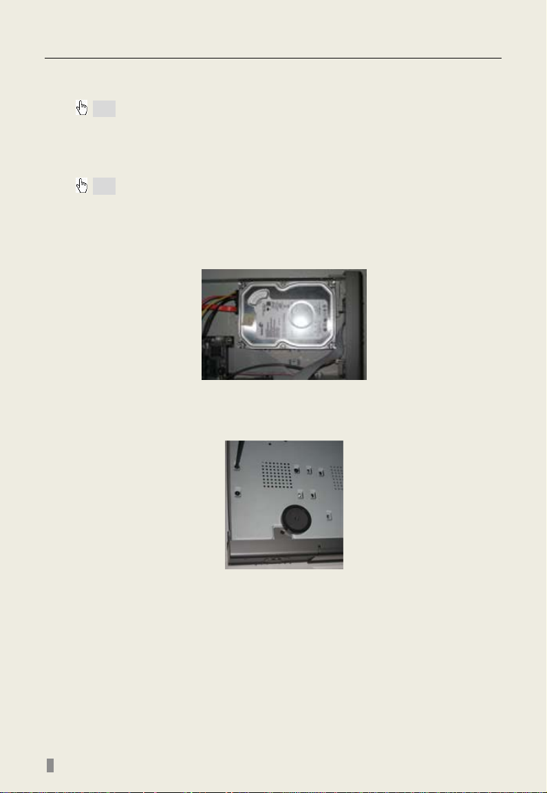
2.1 Installing Hard Drive
Note: 1. Supports two SATA hard drives.
2. Please calculate HDD capacity needed according to the recording se tting.
Please refer to “Appendix B Calculate Recording Capacity”.
STEP1 Unscrew and open the top cover
STEP2 Connect the power and data cables. Place the HDD onto the
bottom case as below.
Fig 2.1 Connect HDD
STEP3 Screw in the HDD as shown below . Note: For easier installation, please connect the power and data cables first, and then screw HDD to base.
Fig 2.2 Screw in HDD
4
Page 9
QSDT8DP DVR User’s Manual
1. Enter search mode
2. ZOOM function enables at PTZ mode
1. Enter play menu
2. IRIS function enables at PTZ mode
1. Rewind
2. SPEED function enables at PTZ mode
1. Quit play mode
2. Exit the current menu or status
1. Direction buttons. Move cursor in setup or pan/tilt
screens
1. System Information
other digitals 0-9
1. Increase the value in setup
2. Enter menu from live view
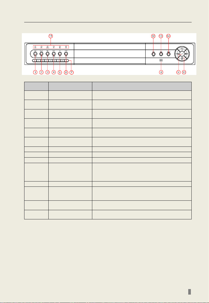
2.2 Front Panel Layout
Fig 2.6 Front Panel
Item Name Description
1 REC/Focus
2 Search/Zoom
3 Play/Iris
4 REW/Speed
5 FF/PTZ
6 STOP/ESC
7 Digital buttons Input numbers or choose camera
8 IR Receiver For remote control
9 Enter button To confirm the choice or setup
10
11 Indicator Working indicators of power, HDD, network, etc
12 Info/10+
13 +/Menu button
14 -/Backup
Direction/Multi-screen
button
1. Record manually
2. FOCUS function enables at PTZ. mode
1. Fast forward
2. Enter P T Z m ode from live view
PTZ
2. Change screen display like single, 4, 9 and 16
2.Double-click is 10; choose channel 10 above with
1. Decrease the value in setup
2. Enter backup mode from live view
Table 2.1 Functions of Front Panel Buttons
5
Page 10
QSDT8DP DVR User’s Manual
Item
Name
Description
Connect to monitor as an AUX output channel for one
channel. only displays video, not menu
5
LAN
Connect to internet
11
VIDEO IN
8 Video inputs for cameras
12
VGA port
VGA output, connect to monitor
13
ALARM OUT
Relay output 1-4. Connect to external alarm.
14
+5V and GND
+5 Voltage and Grounding
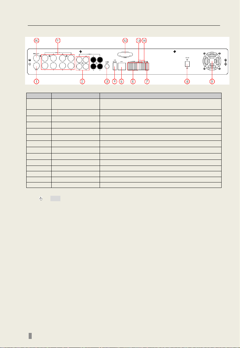
2.3 Rear Panel Layout
Fig 2.7 Rear Panel
1 SPOT OUT
2 AUDIO IN 4-channels audio input
3 AUDIO OUT Audio output, connect to speakers
4 USB MOUSE port Only for USB mouse
6 ALARM IN Connect to external sensor 1-8.
7 RS485 Connect to speed domes
8 POWER INPUT DC 12V
9 FAN For cooling the device
10 VIDEO OUT Connect to monitor
Tab 2.2 Ports on Rear Panel
Note: The resolution of VGA ou tput is 800* 600/60Hz. If connected through VGA po rt,
please assure your display supports this display mode. (Most LCD screens can
adapt to it automatically without manual adjustment)
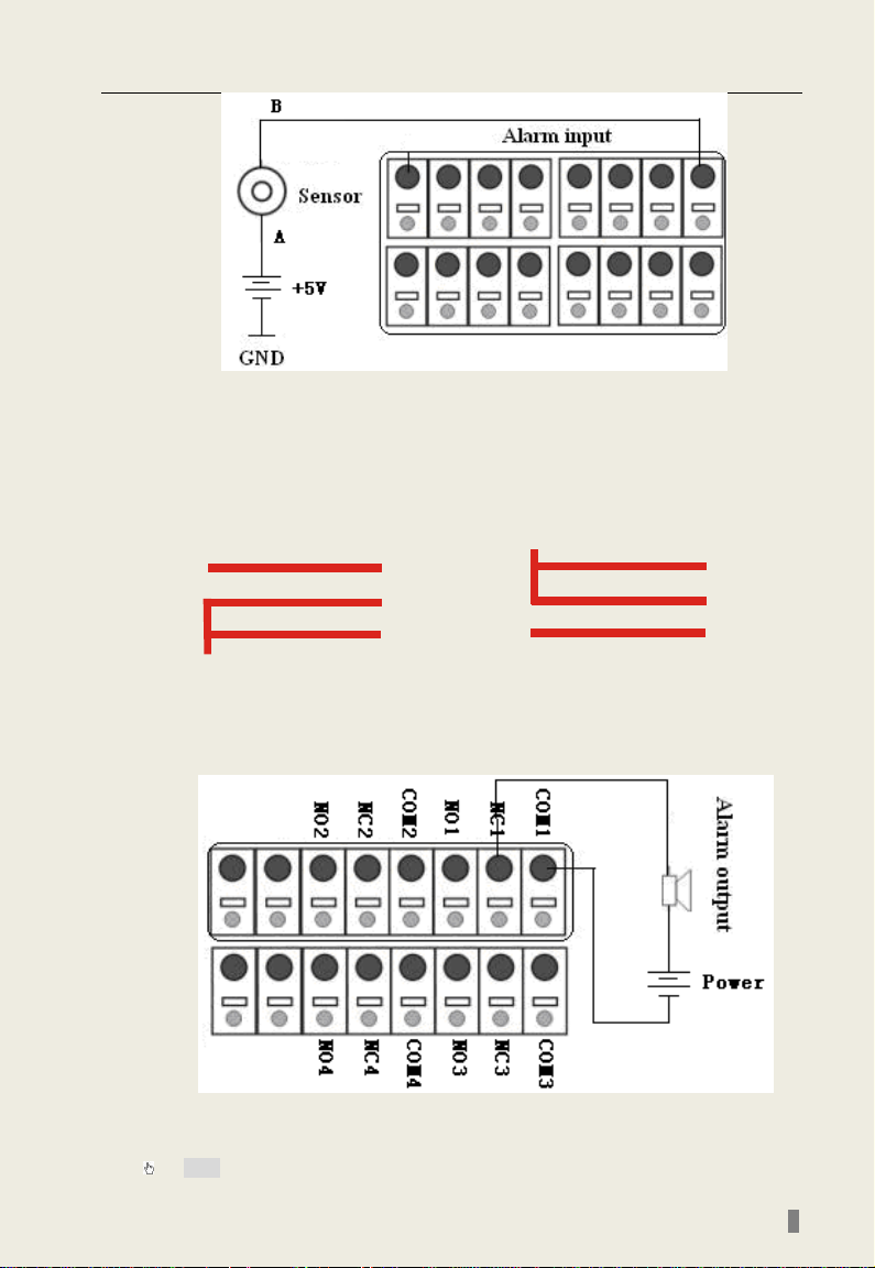
2.3.1 Installing Sensors & Alarms (optional)
The DVR has 8 channel alarm input and 1 channel alarm output.
Alarm Input:
The alarm input is triggered by electric level (High: 5V, Low: 0V). Users
can connect external sensors, like gas detec tor s, smoke detectors and
infrared detectors. Once the DVR detects that the electric lev el meets the
user’s settings it will trigger the DVR recording or alarm out.
For example, a sensor is connected to alarm input1 as Fig 2.8 Cable A
and B will be connected once the sensor detects an event. Users set
Device type as NC (Normal Close), refer to Fig 2.8 It will input +5V (high
level) to input1 when triggered, DVR will start recording.
6
Page 11
QSDT8DP DVR User’s Manual
NO
..
COM
NC
. .
NO
..
COM
NC
. .
Before alarm
After alarm
Fig 2.8 Sensor Connection
Alarm output:
The DVR has 1 channel relay alarm output, which just gives on/off
signal to external alarm. The status of these pin are illustrated as 8.
Fig 2.9 Relay Output Status
Users need connect their alarm according to the NO or NC type of
the alarm. One connection example is shown as Fig 2.9
Note: The power in series must be 277VAC/10A or 30VDC/10A or below
Fig 2.9 Alarm Output Connection
7
Page 12
QSDT8DP DVR User’s Manual
power off.
Get information about the DVR such as firmware version, HDD
information
3
REC Button
To record manually
4
Number Buttons
Input numbers or choose camera
Multi Screen
6
SEARCH Button
To enter search mode
7
MENU Button
To enter menu
8
ENTER Button
To confirm the choice or setup
9
Direction Button
Move cursor in setup or control PTZ camera
10
+/- Button
To increase or decrease the value in setup
Playback
Control Button
12
AUDIO Button
To enable audio output in live mode
Auto Dwell
14
BACKUP Button
To enter backup mode
PTZ Control
To control PTZ camera. Move camera/ZOOM/FOCUS/IRIS/SPEED
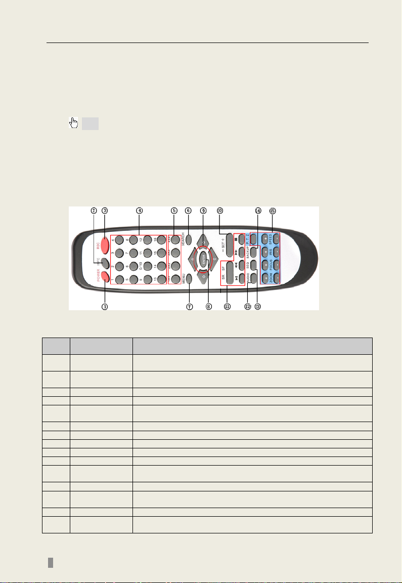
2.4 Remote Control
The remote control uses two AAA batteries, instructions for loading:
STEP1 Open the battery cover of the Remote Control
STEP2 Insert batteries with the poles (+ and -) correctly aligned
STEP3 Replace the battery cover
Note: If remote does not function check the following:
1. Check polarity of batteri es
2. Check the remaining charge in the batteries
3. Check to see if r emote control sensor is blocked
If it doesn't still work, exchange for a new remote control or contact your dealer.
The interface of the remote control is shown in Fig 2.10
Fig 2.10 Remote Control
Item Name Function
1 Power Button
2 INFO Button
Push button softly to stop firmware running before pushing harder to
5
11
13
15
Button
Button
Button
To choose multiple screen display mode
To control playback. Fast forward/rewind/stop/single frame play
To enter auto dwell mode
control
Table 2.3 Functions of Remote Control Buttons
8
Page 13
QSDT8DP DVR User’s Manual
2.5 Controlling with a Mouse
2.5.1 Connecting Mouse
DVR supports USB mouse through the ports on the rear panel, please
refer to Fig 2.10 Remote Control
Note: If mouse is not detected or doesn't work, check below:
1. Unplug/re-plug several times
2. Power off/on several times
3. Try another mouse
2.5.2 Using Mouse In live view:
Click left mouse butto n on o ne cam era to display full screen. Click again
to return to the previous screen display.
Click right button to show the control bar at the bottom of the screen as
in Fig 2.10 Remote Control. Here are all the controls and setup. Click right
mouse button again to hide the control bar.
In setup:
Click left button to enter. Click right button to cancel setup, or return to
the previous screen.
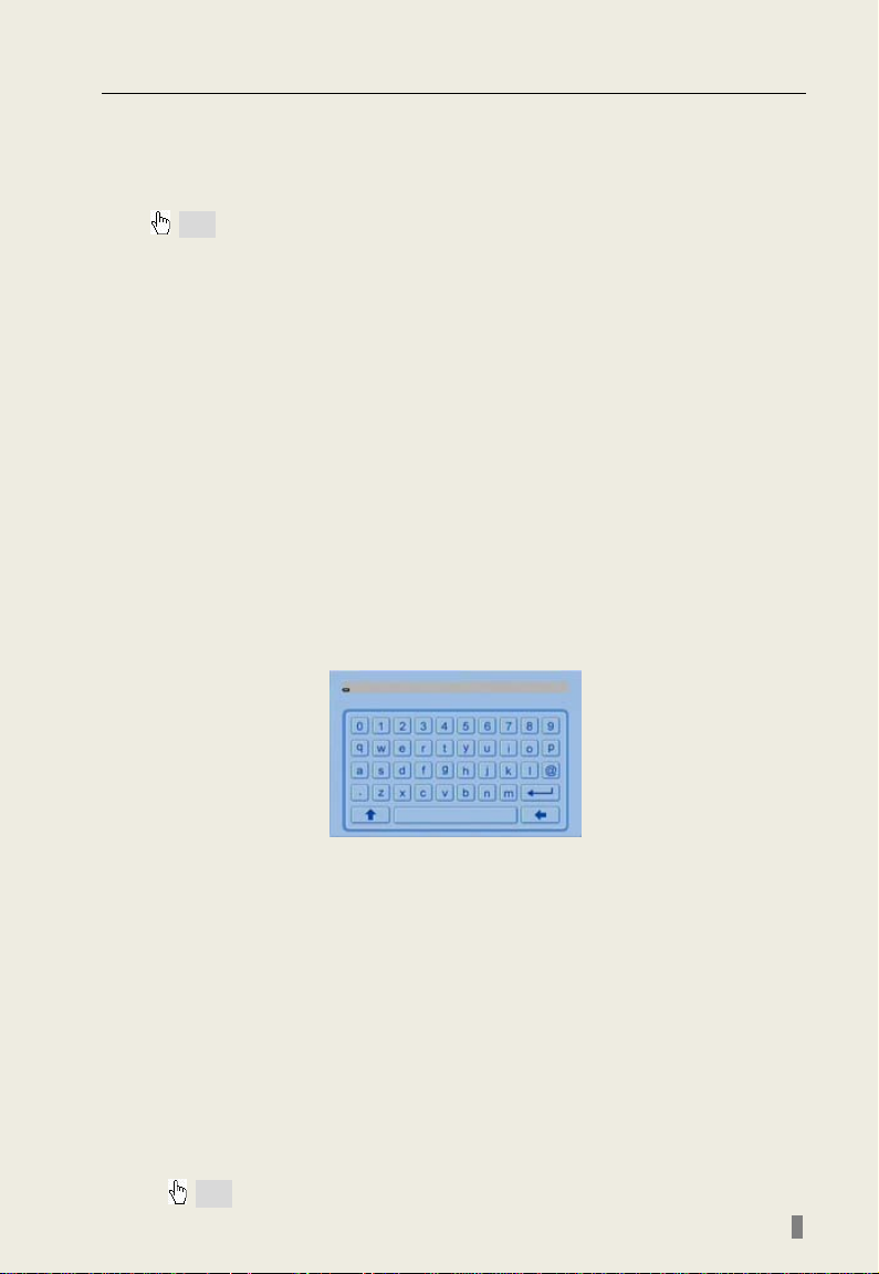
If want to input the value, move cursor to the button and click. An
input window will appear as in
numbers, letters and symbols.
Fig 2.11 Input Window . It supports
Fig 2.11 Input Window
Users can change some values by using the mouse wheel, such a s time.
Move cursor onto the value, and roll the wheel when the value blinks click
it.
It supports mouse dragging, i.e. set motion detection area: click
customized, hold left button an d drag to set motion detection area. Set
schedule: hold left button and drag to set schedule time
In playback: Click left button to choose the options. Click right button to
return to search mode.
In backup: Click left button to choose the options. Click right button to
return to live view.
In PTZ control: Click left button to choose the buttons to control the PTZ.
Click right button to return to searching mode.
Note: Mouse is the default tool in all the operations below unless stated otherwise.
9
Page 14

QSDT8DP DVR User’s Manual
Symbol
Meaning
Symbol
Meaning
Manual recording
Scheduled recording
Motion de tection recording
Alarm recording
HDD
Current working HDD
Space
Size of current HDD
CHAPTER 3 Basic Function Instructions
3.1 Power On/Off
Note: Before you power on the unit, pleas e m ake sure all the connections are good.
Connect the power, the system will show the screen in Fig 3.1 System
Loading
Fig 3.1 System Loading
After that it will enter live in 16 screen mode. The meaning of letters or
symbols on screen are shown in the table below.
Live audio enabled
Free Free space of current HDD
HDD full
Table 3.1 Meaning of Symbols in Live View
10
Fig 3.2 Preview
Live audio disabled
USB devices connected
Page 15

QSDT8DP DVR User’s Manual
To power off safely follow the steps below. Users can close the unit by
remote control, front panel and mouse.
By remote control:
STEP1 Press POWER button, the screen below will appear:
Fig 3.3 Shut down
STEP2 Choose OK. The unit will power off automatically after shutting down software.
STEP3 Disconnect the power
By front p ane l or mouse:
STEP1 Press ENTER button or click right mouse to show menu bar, refer
to Fig 4.1 Control Bar.
STEP2 Click Shut down button, refer to Fig 3.3 Shut down
STEP3 Click OK on the pop-up window. The unit will power off
automatically after shutting down software
STEP4 Disconnect the power
3.2 Login & User Management
Users can log in and out of the DVR system. Users cannot do any other
operations except changing the multi screen dis play once lo gged out.
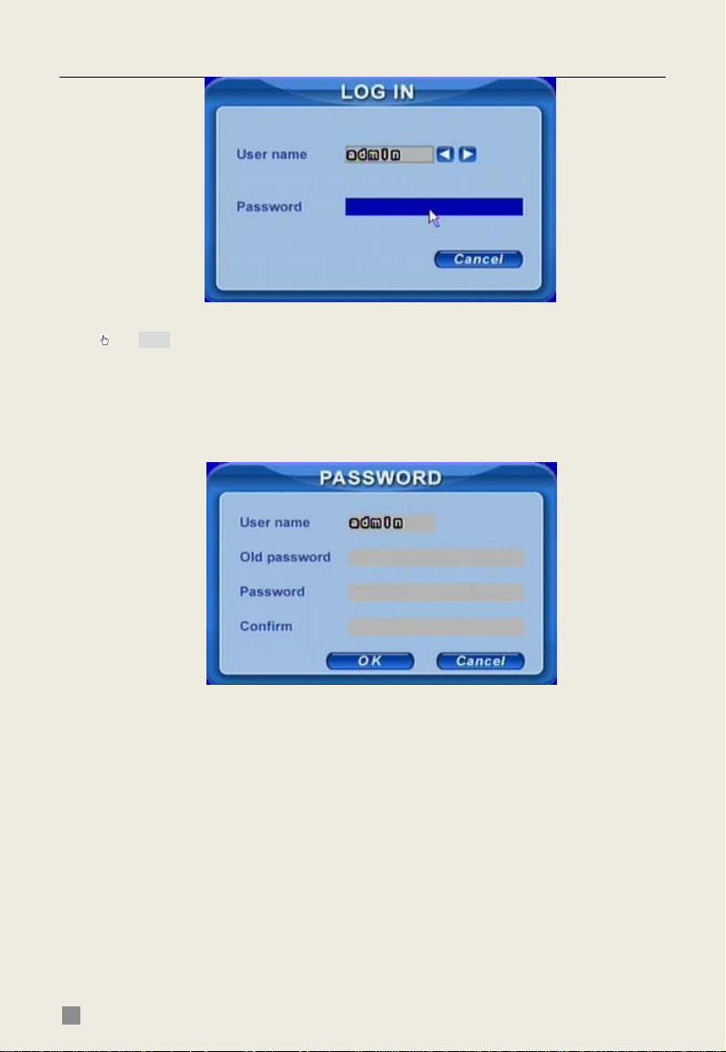
Login:
If logged out press right mou s e button to show the control bar. Press Login,
Search or System etc. A login window w ill appea r, asking for ID and password
shown as Fig 3.4 Login.
11
Page 16
QSDT8DP DVR User’s Manual
Fig 3.4 Login
Note: The default password is admin and 123456.
Change passwor d:
Every user can change his own password.
STEP1 While logged in, click Log in/out on the control bar. A window will
appear with two options. One is for logout, another for password modification.
Click Password, the window will appear as in Fig 3.5 Change Password.
Fig 3.5 Change Password
STEP2 Input the old password. Then input new password 2 times.
STEP3 Press OK button to change.
Add & Delete users:
This unit has a default administrator and two user groups, advance user
and normal user. It supports one administrator and 15 users total.
Administrator can add or delete other users, and change their group level.
Administrator cannot be added or deleted.
12
Page 17

QSDT8DP DVR User’s Manual
Press right mouse button to show the control bar. Enter Menu---->System.
STEP1 Enter USER configuration. Click Add button, see Fig 3.6 Add User.
Fig 3.6 Add User
STEP2 Input user name and password. Choose the user group.
STEP3 Click OK button to add a new user
STEP4 Choose a user, a symbol
will display at the end of the user
information. Click Authority button to change the group level.
STEP5 Press Delete button to delete the user. A security window will
appear as shown below.
STEP6 Click OK button to delete the user
Note: Defining users’ rights
Administrator: can to do everything.
Advance: all functions except entering USER to manage users
Normal: all functions except entering SYSTEM to change the settings.
The number of characters must be 1 or more.
The user name and password is a combination of numbers, letters or symbols.
13
Page 18

QSDT8DP DVR User’s Manual
3.3 Recording
3.3.1 Record Setup
Users need to install and format a HDD, and set all the recording
parameters before recording.
Note: Some vendors sell the DVR with a hard drive already installed, if this is the case
you just need to set the recording parameters.
There are four recording modes. Users can enable them simultaneously,
but only one recording mode works at a time. They have different priorities,
the priority order is below:
Motion detection recording > Sensor recording > Manual recording > Timer
recording
Press right mouse button to show the control bar, refer to Fig 4.1 Control
Bar. Enter Menu---->System.
STEP1 Enter RECORD configuration, refer to Fig 3.7 Record Setup, Select cameras.
Fig 3.7 Record Setup
STEP2 Set Video quality, Frame rate and Resolution.
STEP3 Have Audio checked if you input audio and want to record. Check
Time stamp to record
STEP4 Enable recording function for cameras in Record option.
Note: If you have a camera uncheck here, it will not record in any recording mode.
STEP5 Set Alarm record hold time. It is for post alarm recording.
STEP6 Enable Recycle. It replaces old video with new files after HDD is
full. If you have it unchecked, it will stop recording automatically once HDD is
full
STEP7 Click OK to finish
Note: The higher the Video quality, Frame rate and Res olution, the more storage space
is used every hour.
This Unit supports pre-alarm recording. But there is no option to set the
pre-alarm recording time, the default is 10 seconds
14
Page 19

QSDT8DP DVR User’s Manual
3.3.2 Manual Recording
Just press REC button on the front panel after quitting system setup. Press
Stop button to stop recording.
Or press REC button on remote control, click again to stop.
Or click REC button on the control bar with mouse, click again to stop.
3.3.3 Scheduled Recording
Users can set different schedule times for every day of the week. If you want
a special schedule for one day, you can use the Holiday function.
STEP1 Enter SCHEDULE configuration. Select cameras and Record, see Fig 3.8 Schedule Setup.
Fig 3.8 Schedule Setup
STEP2 The first column lists the 7 days of the week. The rows show 24 hours. Set the schedule time.
Green means checked. Transparent means unchecked. STEP3 Press Add button to select the date if you want a special schedule for a certain day. A window will appear as Fig 3.9 Calendar.
Fig 3.9 Calendar
STEP4 Select the date and set the s c hedul e ti me. If you want to delete this
special schedule, click Delete button
STEP5 Click OK button to finish
The DVR will record automatically once it goes to the time you set.
15
Page 20

QSDT8DP DVR User’s Manual
3.3.4 Motion Detection Recording
This unit supports recording channels and PTZ linking. This means it will
record any cameras, or trigger any speed dome to preset or do auto cruise
once motion is detected on the camera’s channel.
STEP1 Enter MOTION configuration, see Fig 3.10 Motion Detectio n Setup. Select cameras
Fig 3.10 Motion Detection Setup
STEP2 Enable Detection first. Enter Area to set Sensitivity and detection Area. In detection area, red means not active, transparent means active, see Fig 3.11 Motion Detection Area Setup.
Fig 3.11 Motion Detection Area Setup
STEP3 Enter Trigger config uration, see Fig 3.12 Alarm Out Setup
16
Fig 3.12 Alarm Out Setup
Page 21

QSDT8DP DVR User’s Manual
STEP4 Select alarm out and recording channels. It can trigger any alarm
out and cameras to record once motion is detected.
STEP5 Enable or disable Buzzer on board. Select speed dome (PTZ) and
enable preset or auto cruise. Press OK to save
STEP6 Set Hold time. It is the interval time between two consecutive
motion events. If a second motion event is detected during the Hold time, it is
recognized as a continuation of the first motion event. If a sec ond moti on is
detected after Hold time, this motion and the previous are recognized as two
different motion events.
STEP7 Click OK to save settings
STEP8 Enter SCHEDULE configuration. Select Motion and relative
cameras to set, refer to 3.3.3 Schedule recording.
Note: About preset and auto cruise, users can only select one or the other.
The actual post alarm record time equals Hold time in RECORD and Hold time in MOTION
3.3.5 Alarm Recording
This unit supports recording channels and PTZ linking after alarm.
STEP1 Enter ALARM configuration, see Fig 3.13 Sensor Alarm Setup.
Select cameras
Fig 3.13 Sensor Alarm Setup
STEP2 Enable Detection first. Set Device type.
STEP3 Enter Trigger config uration. Set alarm out, recording cameras and
linked PTZ, referring to 3.3.4 Motion Detection Recording STEP4-5
STEP4 Set Alarm in hold time. It is the interval time between the two
adjacent efficient alarms. This is similar with Hold time in MOTION
configuration.
STEP5 Set Alarm out hold time and Buzzer hold time. Click OK to save
settings
STEP6 Enter SCHEDULE configuration. Select Sensor and relative
cameras to set, referring to 3.8 Schedule Setup.
Note: About preset and auto cruise, users can only select one at same time.
The actual post alarm record time equals Hold time in RECORD and Hold time in MOTION
17
Page 22

QSDT8DP DVR User’s Manual
3.4 Playback
This unit supports time search and event search. It displays full or 4
screens in playback. Click right mouse button to show the control bar, refer to
Fig 4.1 Control Bar. Click Search, the window below will appear on the
screen.
Fig 3.14 Search Menu
Time search:
STEP1 Enter Search configuration, select Time search. A window w ill
appear as Fig 3.15 Calendar Search. If there are recordings during a day, the
date will be highlighted.
Fig 3.15 Calendar Search
STEP2 Choose a day to do a time search, as in Fig 3.16 Time Search.
Fig 3.16 Time Search
18
Page 23

QSDT8DP DVR User’s Manual
STEP3 This unit has full and 4 screen playback. Select the screen display
mode (the boxes under the channels) and the channels.
STEP4 If want to change the date, press Date button. Set hour and
minutes of start time. If there is a recording at that time, the boxes will show
green.
STEP5 Click Play button. It will play from the time point you set.
STEP6 Click the function buttons on the screen to do fast
forward/backward, pause, stop, and change the screen mode and re-search,
See Fig 3.17 Playback.
Fig 3.17 Playback
Event search:
STEP1 Enter Search---->Event search. The calendar window will appear
like that of time search
STEP2 Choose a day to find events for, as Fig 3.18 Event Search
19
Page 24

QSDT8DP DVR User’s Manual
Fig 3.18 Event Search
STEP3 Choose camera and event type, motion or sensor.
STEP4 Double click one video file to play.
3.5 Backup & View
STEP1 This unit supports backup to USB Flash through the USB port on
the front panel. Users can also make backup to PC by IE browser via internet,
refer to 6.3.1 STEP2Select the date, channel and event type. Then click
Search. All the files found will be listed in left area.
STEP2 Select a file, and click Play button to do remote playback. The
following steps are the same as STEP5-6 of time search above.
Take USB flash backup as an example. You can push the Backup button on
the front of the DVR or press right mouse button to show the control bar, refer
to Fig 4.1 Control Bar.
At DVR location:
STEP3 Enter Backup interface, shown as Fig 3.19 Backup Setup
20
Page 25

QSDT8DP DVR User’s Manual
Fig 3.19 Backup Setup
STEP4 Choose the camera. And set the start and end time. Click Date
button to change the date.
STEP5 Click the Backup button. A window will appear as shown in Fig 3.20
Backup Information.
Fig 3.20 Backup Information
STEP6 Press OK button. It will b egin to write the video files you selected to the backup device, and display a process bar as shown below:
21
Page 26

QSDT8DP DVR User’s Manual
STEP7 It will show “Backup complete” after finished, as shown below:
Check & View:
Users can view the backup with third party software like Real Player or
Windows Media Player directly. Users can also view with the special software
attached with the files during backup. Below are the steps to view the backup
with the special software.
STEP1 Move the backup device to a computer. Enter the backup folder and
open the viewer.
Fig 3.21 Backup Player
① Search area ② video display area
③ Video data area ④ Control area
⑤ AVI converting
22
Page 27

QSDT8DP DVR User’s Manual
STEP2 Click Browse to choose the folder which contains the video backup, as in Fig 3.22 Choose Backup Folder.
Fig 3.22 Choose Backup Folder
STEP3 Set the date and channels. It will show the recorded video in area③ with green at the top as in Fig 3.23 Backup Data Search.
Fig 3.23 Backup Data Search
If using event search, it will list event files at the bottom of area①
STEP4 Drag the slide bar to the st ar t time point, click play button to view. It supports multi screen display. Users can do fast forward/backward, record, play audio etc, as shown below.
23
Page 28

QSDT8DP DVR User’s Manual
Index
Definition
Index
Definition
Index
Definition
Index
Definition
Play ② Pause
Stop ④ Snap only in pause.
Forward/Rewi nd
Record
Volume
Screen mode
①
⑤
Fig 3.24 Play Backup Files
⑥
③
⑦
⑧
Refer to Fig 6.3
Tab 3.2 Backup View Control
STEP5 Program supports AVI converter. Click “Change File to AVI”. The
converter will appear.
STEP6 Click Browse to choose the folder which contains the video backup.
Set the start/end time, select the channels, and then Click search button. It
will show backup files in the file display area as shown in Fig 3.25 AVI
Converter.
24
Page 29

QSDT8DP DVR User’s Manual
Fig 3.25 AVI Converter
STEP8 Select the files. Click Change button, it will start converting the files
and show the progress at the bottom.
STEP9 When the progress bar shows 100% it is finished. Users can play
the AVI files with a third party player directly.
STEP10 For more information about network backup, please refer to 6.3.1
STEP2Select the date, channel and event type. Then click Search. All the
files found will be listed in left area.
STEP11 Select a file, and click Play button to do remote playback. The
following steps are the same as STEP5-6 of time search above.
25
Page 30

QSDT8DP DVR User’s Manual
3.6 PTZ Control
Please connect speed domes to the DVR via RS485 first, refer to 2.3.1
Rear Panel. Make sure the speed dome has a protocol this DVR suppor t s and
set the parameters according to its manual.
STEP1 Press right mouse button to show the control bar. Enter Menu---->System--->P.T.Z, see Fig 3.26.
Fig 3.26 PTZ Setup
STEP2 Set protocol, baud rate, and address according to the parameters
of the speed dome.
STEP3 Click Set button at right of Preset. Here users can set presets,
shown as Fig 3.27 Set Presets. Adjust the speed dome. Select a preset and
click to save. Users can set 16 presets tota l.
Fig 3.27 Set Presets
STEP4 Click Set button at right of Cruise. Here users can set cruise track, shown as Fig 3.28 Set Cruise. Choose the preset, set stay time of every preset. Click + button to add the preset to the left preset for cruise track.
26
Page 31

QSDT8DP DVR User’s Manual
Fig 3.28 Set Cruise
STEP5 Select a preset in left preset list, click – button to delete the preset.
Click ↑,↓,↑,↓ to adjust the sequence of the presets in the auto cruise setup.
Click Save to save and return t o the prev iou s interf ace.
STEP6 Click OK button to save and ex it . Pr ess right mo use button to show the control bar. Click PTZ to enter PTZ control, shown as Fig 3.29 PTZ Control.
Fig 3.29 PTZ Control
STEP7 Select the speed dome. Click the direction buttons to move the
camera. Click the relative + and – buttons to adjust zoom, focus, IRIS and
speed. Click □ button to stop the change.
STEP8 Select the preset, the speed dome will go to that point directly.
Select Cruise, it will do auto cruise.
27
Page 32

QSDT8DP DVR User’s Manual
Video quality
Alarm Switch
Motion switch
HTTP & server ports
Add users
Disk manager
CHAPTER 4 Menu Setup Guide
4.1 Menu Na vigation
Menu Option Menu Option
Device name & ID
Video format
Language
Basic
Date &time setup
Live audio switch
Authorization check
switch
Live
Camera name
Camera mask
Name & time switch
SPOT out switch
Color adjustment
Record
Alarm
Network
User
Frame rate
Record switch
Resolution
Recycle switch
Post alarm record time
Sensor type
Alarm out &out time
setup
Recorded cameras and
PTZ linking
IP address setup
PPPoE
Network video setup
DDNS
Delete users
Change authorization
Tab 4.1 Menu Navigation
Schedule
Motion
PTZ
Tools
Recording schedule
Motion schedule
Sensor schedule
Sensitivity & detection
area setup
Alarm out & out time
setup
Recorded cameras and
PTZ linking
Protocol, baud rate and
address
Speed setup
Presets setup
Cruise setup
Update
Load default
28
Page 33

QSDT8DP DVR User’s Manual
4.2 Main Menu Setup
Click right mouse button, or press ENTER button on the front panel,
the control bar will show on the bottom of the screen as in
Control Bar.
Fig 4.1 Control Bar
Move the cursor to Menu and click, the pop up menu will show as Fig 4.2
Pop up Menu
Fig 4.2 Pop up Menu
Select System. A graphic user interface will show as Fig 4.3 System Setup.
Fig 4.1
Fig 4.3 System Setup
Press MENU button on the front panel or remote control. The interface
above will appear.
Note: Default admin password is 123456. Only adminis trator and adva n ce user can
enter system setup and do setup.
DVR needs to reboot after some parameters are changed, like video format.
29
Page 34

QSDT8DP DVR User’s Manual
4.2.1 Basic Configuration
Click BASIC to enter basic configuration shown as Fig 4.4 Basic .
Fig 4.4 Basic Configuration
Here users can set video system, menu language, audio, time and
authorization check. The following are the definitions of each option.
Device name: The name of the unit. It may display on the client end or
CMS, which helps users to recognize the unit remotely.
Device ID: It is used to identify multiple devices at the same place. Users
can manage them by remote control.
Video format: Options are PAL and NTSC. Users make the choice
according to format of the cameras.
Language: Set the menu language.
Authorization check: If enabled DVR needs user name and password
when user wants to enter system setup, playback, bac kup et c.
Audio: Enables audio in live view. Users can choose a channel for audio.
Date format: Three format options, YY-MM-DD, DD-MM-YY, MM-DD-YY.
System time: Set the time. While the unit is recordin g users cannot ch ange
the time. When recording, click Adjust button, a security window will appear.
30
Page 35

QSDT8DP DVR User’s Manual
4.2.2 Live Configuration
Click LIVE to enter live configuration shown as Fig 4.5 Live Configuration
Fig 4.5 Live Configuration
Here users can set name/time display, picture color and hide cameras. The
following are the definitions of each option.
Camera name: Set camera name. It can be a combinati on of numbers,
letters and symbols.
Show name: Display camera name in live view.
Hide: Hide the picture in live. Unauthorized users cannot view the camera.
But it still works in the background recording.
Show time: Display time in live view.
Dwell time: Is available for both Sequence and SPOT simultaneously. This
unit has 2 channels of video o utput, re fer to 2.3.1 Rear Panel. One is the main
output; the other is a spot outp ut. Users can set the display time of cameras in
auto dwell and spot out.
SPOT enable: Enable spot video output.
Click Set button, a window will appear as shown in Fig 4.6 Color
Adjustment.
Fig 4.6 Color Adjustment
Adjust Brightness, Hue, Saturation, and Contrast in live view here.
Default: Set the color to the default value.
31
Page 36

QSDT8DP DVR User’s Manual
4.2.3 Record Configuration
Click RECORD to enter record configuration shown as Fig 4.7 Record
Configuration.
Fig 4.7 Record Configuration
Here users can set record quality, frame rate, resolution and recycle. The
following are the definitions of each option.
Video quality: There are 5 options from lowest to highest. The higher the
value is, the clearer the recorded picture is.
Frame rate: Set recording frame rate.
Audio: Enable audio recording.
Time stamp: Record the current time to video file if checked.
Record: Switch on/off recording function for every camera. DVR records
the camera only if the camera’s option is checked here. Then you can use
manual, schedule, motion detection and sensor alarm recording options for
the camera.
Resolution: DVR supports CIF and D1. D1 option is not currently
available.
Alarm record hold time(S): Set th e l engt h o f time DVR records after alarm
finishes. It has 4 options, 30, 60, 120 and 180 seconds.
Recycle: Enable HDD recycle. If checked hard drive will overwrite older
files once it is full. If unchecked it will stop recording when HDD is full.
Note: Video quality, frame rate and resolution are closely related to used storage space.
The higher the value is, the higher the bit rate and more space recordings take up on the hard
drive.
32
Page 37

QSDT8DP DVR User’s Manual
4.2.4 Schedule Configuration
Click SCHEDULE to enter schedule configuration shown as Fig 4.8
Schedule Configuration.
Fig 4.8 Schedule Configuration
Here users can set schedule for timed recording, motion detection and
sensor alarm respectively. The following are the definitions of each option:
Always, Motion and Sensor: refer to record schedule, motion schedule
and alarm schedule respectively.
The first column shows the 7 days of the week from Sunday to Saturday.
The rows refer to 24 hours. Click the boxes or hold mouse to drag to set the
schedule time. Green means chec ked. Transparent means unchecked.
Add: Users can set the schedule for a certain day by d at e. Clic k Add to add
date as shown in Fig 3.9 Calendar.
Delete: Delete holiday schedule.
4.2.5 Alarm Configuration
Click ALARM to enter alarm configur ation as in Fig 4.9 Alarm Configur ation.
Fig 4.9 Alarm Configuration
33
Page 38

QSDT8DP DVR User’s Manual
Here users can set sens or t y p e, al arm trigger and alarm time . The following
are the definitions of each option.
Device type: NC and NO (Normal Close and Normal Open). Set the value
according to the alarm signal level of the sensors.
Enable: Enable sensor alarm.
Trigger: Set alarm o utpu t, recor ding channe l and speed do me linking. Click
Set button, a window will appear shown as Fig 4.10 Alarm Out Configuration.
Fig 4.10 Alarm Out Configuration
Alarm out: Set relay alarm out channel. You can select any alarm
channels.
To record: Set recording channels. You can select any record channels. It
will record on the cameras you choose here when alarm triggered.
Buzzer: Enable on board buzzer for alarm.
To P.T.Z CH: Set linked preset and cruise for alarm. You can select any
channel and multi channels as linked channels.
Alarm in hold time(S): The interval time between two consecutive sensor
alarm events. If a second alarm is detected within Hold time, it is recognized
as a continuous alarm. If a second alarm is detected after hold time, the
second alarm and the previous one are recognized as two different alarm
events.
Alarm out hold time(S): Set relay alarm out time after alarm is triggered.
Buzzer hold time(S): set on board buzzer time after alarm is triggered.
34
Page 39

QSDT8DP DVR User’s Manual
4.2.6 Motion Configuration
Click MOTION to enter motion configuration shown as Fig 4.11 Motion
Configuration.
Fig 4.11 Motion Configuration
Here users can set motion sensitivity, detection area and alarm out. The
following are the definitions of each option:
Enable: Enable motion detection.
Trigger: Setup similar with that of sensor alarm, but linked speed domes
need to use different channels, i.e. if users enable motion detection on
camera 1, the linked speed domes must be cameras 2-16.
Area: Set s ensitivity and motion detection area. DVR supports multiple
detection areas as shown in Fig 4.12 Detection Are a Configuration. Click the
blocks or drag mouse to enable or disable. Red means unavailable,
transparent means available. Click Save to save and exit.
Fig 4.12 Detection Area Configuration
Sensitivity: Set detection sensitivity from 1-8, 8 is most sensitive. The
default is 4.
Exit: Quit without saving
Hold time(S): The interval time between two consecutive motion events,
similar to that of sensor alarm.
35
Page 40

QSDT8DP DVR User’s Manual
4.2.7 Network Configuration
Click NETWORK to enter network configuration as shown in Fig 4.13
Network Configuration.
Fig 4.13 Network Configuration
This unit supports DHCP, PPPoE, DDNS. Users enable network function,
and configure IP address, DDNS, transmission video parameters here. The
following are the definitions of each option:
HTTP port: The default is 80. If users change the value, they need add the
port number when typing the IP address in I E address blank, i. e. set HTTP
port to 82, IP address to 192.168.0.25. Users need input
http://192.168.0.25:82 in IE brow ser.
Server port: Communication port, 2000 by default
DHCP: Enable DHCP. For this feature to work you need to enable DHCP in
the router or virtual server. When enabled the unit will get IP address
information automatically from the router instead of inputting IP, Subnet, and
Gateway manually. After you allow the router to assign the addresses you
should go to the info button on the DVR or remote and see what addresses
where assigned, and then go back to the Network Configuration, remove the
checkmark from DHCP and manually enter the IP addresses assigned by the
router into the spaces. This way your addresses will not change if the system
is rebooted.
IP, Subnet, Gateway, DNS1 and 2: IP address information. If users don’t
enable DHCP it is necessary to input the IPs manually here.
PPPoE: Enable PPPoE. If users connect the DVR to internet directly by
ADSL, not through a router or a virtual server, enable this option.
User name, Password: Account information of PPPoE. Input information
you get from your ISP.
36
Page 41

QSDT8DP DVR User’s Manual
DDNS: Click DDNS, a window will appear as shown in Fig 4.14 DDNS
Configuration. DVR supports DYNDNS and MYQ-SEE. Users need register
www.dyndns.com or myq-see.com. Then input registered ID and password
at
here. Click OK button. The unit will connect Through DYNDNS or MYQ-SEE.
Fig 4.14 DDNS Configuration
Server: Select DDNS server.
User name and Password: Input registered information from DDNS
provider.
This unit supports dual stream. Users can set pic ture qual ity, frame rate and
resolution separately for network, according to the network bandwidth. Click
Video to enter the configuration interface shown as Fig 4.15 Network Video
Configuration.
Fig 4.15 Network Video Config uration
Video quality: Network picture quality.
Frame rate: There are two options, 1 and 3 fps.
Resolution: Currently only has CIF available.
Time stamp: Display time in remote preview.
37
 Loading...